diagram OPEL GT-R 1973 Service Manual
[x] Cancel search | Manufacturer: OPEL, Model Year: 1973, Model line: GT-R, Model: OPEL GT-R 1973Pages: 625, PDF Size: 17.22 MB
Page 5 of 625

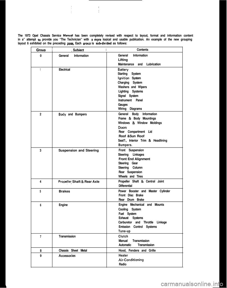
The 1973 Opel Chassis Service MayI has been completely revised with respect to layout, format and information content
in a” attempt
to provide you “The Technician” with a tiore logical and usable publication. An example of the new grouping
layout 6 exhibited on the preceding
page. Each wow is rubdivided as follows:
Grouo 1
_. _
Subiect IIContents.
0
General InformationIGeneral InformationLifting
Maintenance and Lubrication
1ElectricalBattery
Starting System
lgriition System
Charging System
Washers and Wipers
Lighting Systems
Signal SystemI
Instrument Panel
Gauges
Wiring Diagrams
2
Body and Bumpers:General Body InformationI
Frame & Body Mountings
Windows
& Window Moldings
DONS
Rear Compartment LidRoof &Sun Roof
Seat?., Interior Trim & Headlining
Bumpers.
3Suspension and Steering
Front Suspension
Steering Linkages1Front End Alignment
Steering Gear
Steering Column
Rear Suspension
Wheels and Tires
4
Propelley Shaft & Rear AxlePropeller Shaft & Central Joint
Differential
5Brakes ~Power Booster and Master Cylinder
Front Disc BrakeI
Rear Drum Brake
6EngineEngine Mechanical and Mounts
Cooling System
Fuel System
Exhaust Systems
Carburetor and Throttle Linkage
Emission Control Systems
Tune-up
7TransmissionClutch
Manual Transmission
Automatic Transmission
BChassis Sheet MetalHood, Fenders and Grille
9
Accessol;iesHeaterAirConditioning
Radio
Page 22 of 625

ELECTRICALGROUP 1
Section
IAIBICIDIE
IFIGIH
II
IJTitle
Battery and Cables. . . . . .
StartingSystem. . . . . . . . . . . .
Ignition System, .
ChargingSystemWashers and Wipers
.,
LightingSystems
SignalSystems
instrument Panel.........
Gauges...........................Wiring Circuit Diagram:
Page No.
lA- 2lB-10lC-18
1 D-28
1 E-37
1 F-45
1 G-54
1 H-57
1 l-65
1 J-72
Page 50 of 625

CHARGING SYSTEMlD- 29
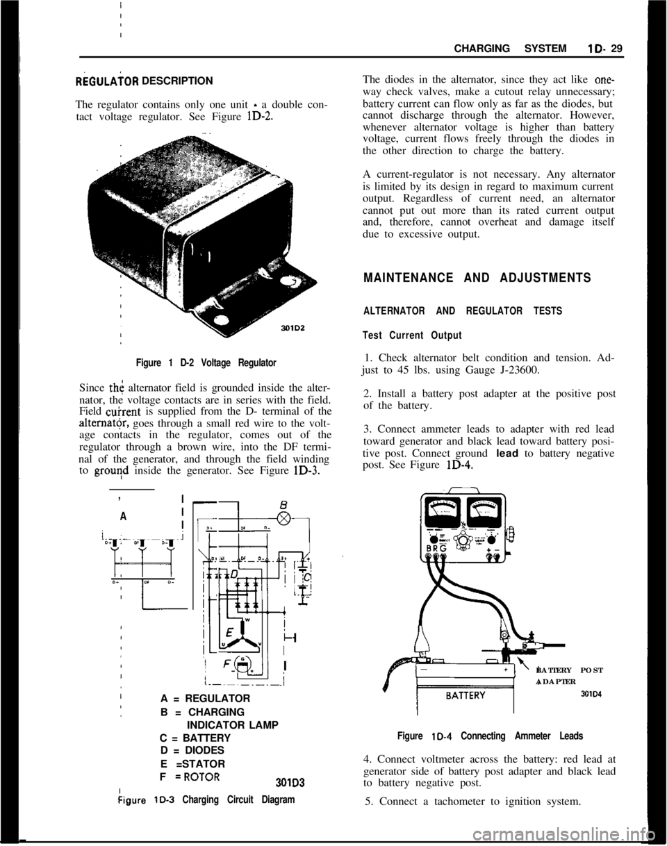
REGULAiOR DESCRIPTION
The regulator contains only one unit - a double con-
tact voltage regulator. See Figure
lD-2.
I Figure 1 D-2 Voltage Regulator
Since th< alternator field is grounded inside the alter-
nator, the voltage contacts are in series with the field.
Field
&rent is supplied from the D- terminal of the
alter”@, goes through a small red wire to the volt-
age contacts in the regulator, comes out of the
regulator through a brown wire, into the DF termi-
nal of the generator, and through the field winding to
grouqd inside the generator. See Figure lD-3.
:
,
!
/ I
’ A I
j
/ I
-
IF
O?
i 2
j
:
:
k
I
I
.i
A = REGULATOR
B = CHARGING
INDICATOR LAMP
C = BATTERY D = DIODES
E =STATOR
I
I F
=ROTOR301D3
kigure
lD-3 Charging Circuit Diagram
The diodes in the alternator, since they act like one-
way check valves, make a cutout relay unnecessary;
battery current can flow only as far as the diodes, but
cannot discharge through the alternator. However,
whenever alternator voltage is higher than battery
voltage, current flows freely through the diodes in
the other direction to charge the battery.
A current-regulator is not necessary. Any alternator
is limited by its design in regard to maximum current
output. Regardless of current need, an alternator
cannot put out more than its rated current output
and, therefore, cannot overheat and damage itself
due to excessive output.
MAINTENANCE AND ADJUSTMENTS
ALTERNATOR AND REGULATOR TESTS
Test Current Output
1. Check alternator belt condition and tension. Ad-
just to 45 lbs. using Gauge J-23600.
2. Install a battery post adapter at the positive post
of the battery.
3. Connect ammeter leads to adapter with red lead
toward generator and black lead toward battery posi-
tive post. Connect ground
lead to battery negative
post. See Figure
lD-4.
BATTERY POST
ADAPTER
SOID
Figure lD-4 Connecting Ammeter Leads
4. Connect voltmeter across the battery: red lead at
generator side of battery post adapter and black lead
to battery negative post.
5. Connect a tachometer to ignition system.
Page 93 of 625

1 J- 72 1973 OPEL SERVICE MANUAL
I
WIRING IDIAGRAMS
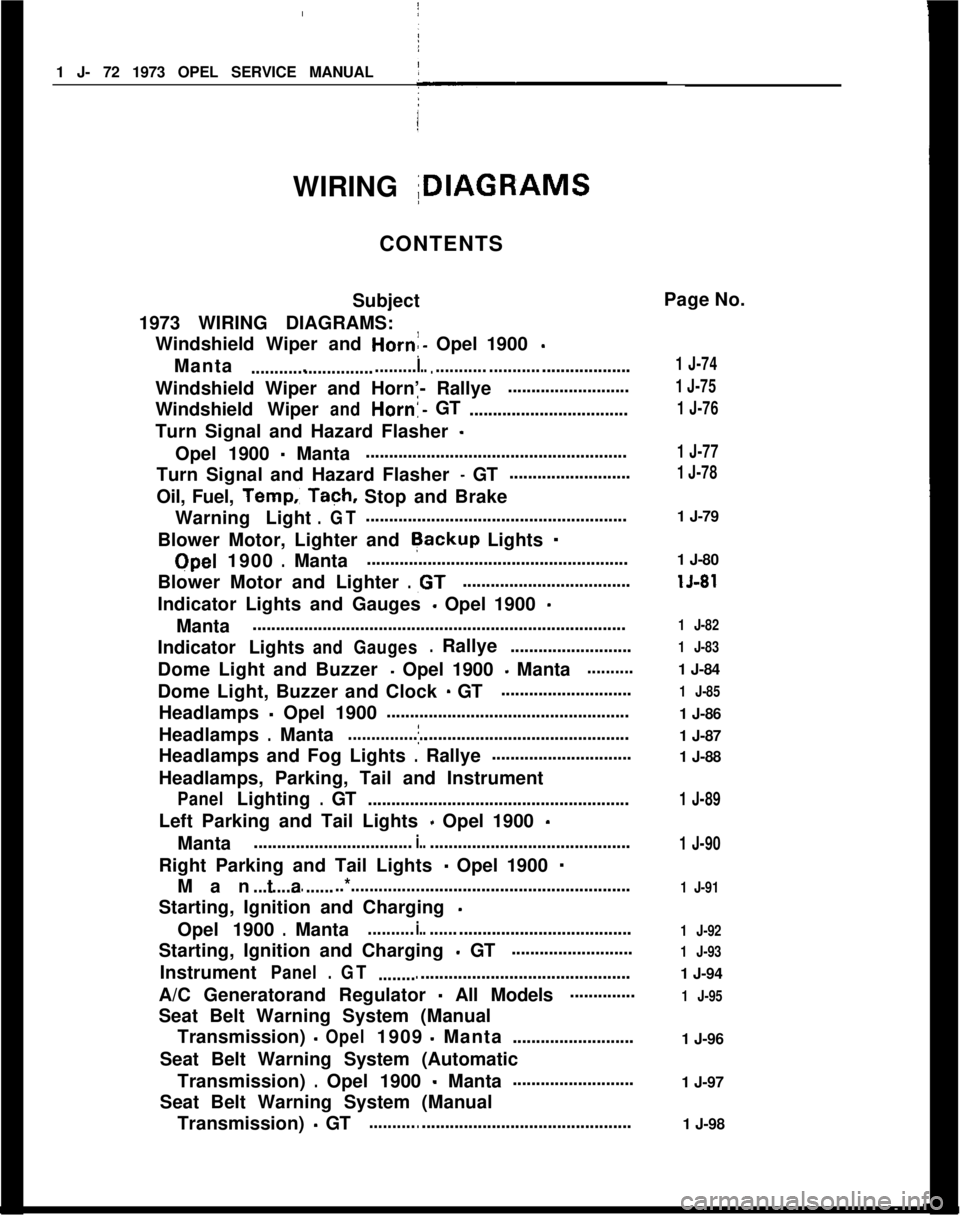
CONTENTS
Subject
1973 WIRING DIAGRAMS: Windshield Wiper and
Horn:- Opel 1900 -
Manta....................................I.............. ..............................
Windshield Wiper and Horn’- Rallye ..........................
Windshield Wiper
andHorn!-GT
..................................
Turn Signal and Hazard Flasher
-
Opel 1900 - Manta !
........................................................
Turn Signal and Hazard Flasher
- GT ..........................
Oil, Fuel,
Temp.: Tach, Stop and Brake
Warning Light
.GT........................................................
Blower Motor, Lighter and
Rackup Lights -
Qpel 1900.Manta ........................................................
Blower Motor and Lighter
.,GT....................................
Indicator Lights and Gauges
- Opel 1900 -
Manta ........................................................................\
........
Indicator Lights
andGauges.Rallye ..........................
Dome Light and Buzzer
- Opel 1900 - Manta..........
Dome Light, Buzzer and Clock - GT ............................
Headlamps
- Opel 1900 ’
....................................................
Headlamps
.Mantaj............................................................
Headlamps and Fog Lights
.Rallye ..............................
Headlamps, Parking, Tail and Instrument
PanelLighting.GT ........................................................
Left Parking and Tail Lights
- Opel 1900 -
Manta ..................................i.............................................
Right Parking and Tail Lights
- Opel 1900 -
Manta................. ..*............................................................
Starting, Ignition and Charging
-
Opel 1900.Manta..........i.............................................
Starting, Ignition and Charging
- GT ..........................
Instrument
Panel.GT ......................................................
A/C Generatorand Regulator
- All Models..............
Seat Belt Warning System (Manual Transmission)
-Opel1909-Manta ..........................
Seat Belt Warning System (Automatic Transmission)
.Opel 1900 - Manta..........................
Seat Belt Warning System (Manual Transmission)
- GT........................................................ Page No.
1 J-74
1 J-75
1 J-76
1 J-77
1 J-78
1 J-79
1 J-80
lJ-81
1 J-82
1 J-83
1 J-84
1 J-85
1 J-86
1 J-87
1 J-88
1 J-89
1 J-90
1 J-91
1 J-92
1 J-93
1 J-94
1 J-95
1 J-96
1 J-97
1 J-98
Page 94 of 625

I
/WIRING DIAGRAMS13-73ISeat Belt Warning System (Automatic
Page No.Transmission)
.GT.......................................................lJ-99HeatedRear Glass
.Opel1900.Manta...................15-100Heated Rear Glass
.GT..................................................*,lJ-101Opel 1900 Color Schematic.........................................
lJ-103Manta
ColorSchematic.................................................1 J-105GT
ColorSchematic
.........................................................1 J-107
Page 96 of 625

I
IWIRING DIAGRAMSlJ- 75
Figure lJ-2 Windshield Wiper and Horn
- Rallye
Page 98 of 625

!I
I
I
,WIRING DIAGRAMS1J. 77
I
IFigure 1 J-4 Turn Signal and Hazard Flasher . Opel 1900 - Manta
I
Page 100 of 625

I
WIRING DIAGRAMS15.79
IIFigure lJ-6
Oil. Fuel. Temp. Tach, Stop and Brake Warning Light. GT
I
Page 102 of 625

I
WIRING DIAGRAMSlJ- 81r
Figure 1 J-8 Blower and Lighter
- GT
Page 104 of 625

I
IWIRING DIAGRAMSIJ-83I
Figure 1 J-10 Indicator Lights and Gauges
- Ratlye