fuse OPEL GT-R 1973 Service Manual
[x] Cancel search | Manufacturer: OPEL, Model Year: 1973, Model line: GT-R, Model: OPEL GT-R 1973Pages: 625, PDF Size: 17.22 MB
Page 20 of 625
LUBRICATION AND MAINTENANCE OC-11
Throttle Linkage
Check for damaged or missing parts, interference or
binding. Any deficiencies should be corrected with-
out delay.
Headlights
Check for proper aim. Correct as necessary. More
frequent checks should be made if oncoming motor-
ists signal when you are already using your low
beams, or if illumination of the area ‘ahead seems
inadequate.
Underbody
In geographic areas using a heavy concentration of
road salt or other corrosive materials for snow re-
moval or road dust control, flush and inspect the
complete under side of the car at least once each
year, preferably after a winter’s exposure. Particular
attention should be given to cleaning out underbody
members where dirt and other foreign materials may
have collected.
EMISSION CONTROL MAINTENANCE
Thermostatically Controlled Air Cleaner
Inspect installation to make certain that all hoses and
ducts are connected and correctly installed. Also,
check valve for proper operation.
Carburetor Choke
Check choke mechanism for free operation. A bind-
ing condition may have developed from petroleum
gum formation on the choke shaft or from overtight-
ening of air cleaner clamp. Also check electric choke
terminal connections and fuse.
Timing, Dwell and Distributor
Adjust timing and dwell accurately as outlined under
Tune-Up in Group 6 at the first 4 months or 6,ooOmiles of operation, then at 12 month or
12,OQO mile
intervals. Adjustments must be made with test equip-
ment known to be accurate.
Replace distributor points every 12 months or 12,000
miles and carefully clean and inspect the complete
distributor cap to prevent misfiring and deteriora-
tion.
Carburetor and Idle
SpeedTorque carburetor attaching bolts and/or nuts to 12
ft.lbs. to compensate for compression of gasket atiirst 4 months or 6,000 miles of vehicle operation.Adjust idle speed to specifications with known accu-
rate equipment.
Proper functioning of the carburetor is particularly
essential to control of emissions. Correct mixtures
for emission compliance and idle quality have been
preset by Opel. Plastic idle mixture limiters have
been installed on the idle mixture screw, idle air
screw, and throttle stop screw to preclude unauthor-
ized adjustment. The plastic caps on the idle mixture
screw and the idle adjustment screw must be
removed to perform an idle speed adjustment. The
plastic cap on the throttle stop screw is not to be
removed unless some major carburetor repair or re-
placement which affects the throttle stop screw ad-
justment has been necessary.
Carburetor Fuel Inlet Filter
Replace filter at 12 month or
12,OCO mile intervals
or more often if clogged.
Spark Plugs
Replace at
6,ooO mile intervals when operating with
leaded fuels or at 12,000 mile intervals when using
unleaded fuels. Use of leaded fuels results in lead
deposits on spark plugs and can cause misfiring at
mileages less than
12,OilO miles. Where misfiring oc-
curs prior to
6,ooO miles, spark plugs in good condi-
tion can often be cleaned, tested and reinstalled in an
engine with acceptable results.
Spark Plug Wires
Inspect spark plug wires for evidence of checking or
cracking of exterior insulation and tight fit in the
distributor cap and at the spark plugs. Exterior of
wires should be cleaned, any evidence of corrosion
on ends removed and wire replace if deteriorated.
Positive Crankcase Ventilation System
The PCV metered orifice should be cleaned at 12,000
mile intervals under normal use, and at 6,000 mile
intervals when the vehicle is used under the follow-
ing conditions: driving in dusty conditions, extensive
idling, trailer pulling and short trip operation at
freezing temperatures (engine not thoroughly
warmed-up).
Evaporation Control System
Check all fuel and vapor lines and hoses for proper
connections and correct routing as well as condition.
Remove canister and check for cracks or damage.
Replace damaged or deteriorated parts as necessary.
Replace filter in open end of canister at 24month/24,000 mile intervals.
Page 29 of 625
1A. 81873 OPEL SERVICE MANUALELECTROLYTESPECIFIC GRAVITY
TEMPERATURE
(F)CORRECTION
-+0&&n _
THERMOMETER 30”
EXAMPLE A:
--,012---,016---,026
- -.02h
- -.028
- -.032~
-.036
YEXAMPLE 6:TEMPERATURE = 120”
i.TEMPERATURE = -0” F.HYDROMETER = ,,230HYDRdiETER
= 1.230
READINGREADING
‘,9R2Ro~CF;‘“” = +.0,6go!RFfCilON = .,032
TRUE SPECIFIC = ,.246
GRAVITY;RU”v;,‘;CIFIC = 1.198
3xA‘l
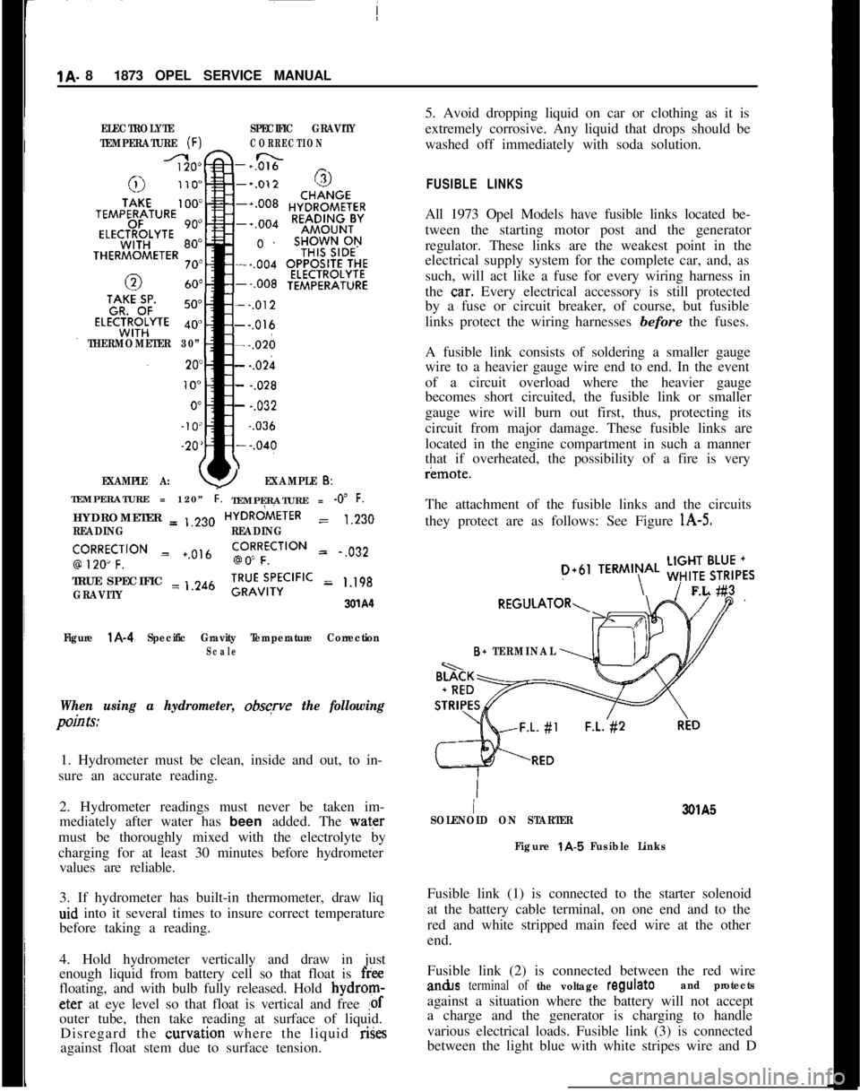
Figure
l A-4 Specific Gravity Temperature CorrectionScale
When using a hydrometer, obsqve the following
pain Is:1. Hydrometer must be clean, inside and out, to in-
sure an accurate reading.
2. Hydrometer readings must never be taken im-
mediately after water has been added. The water
must be thoroughly mixed with the electrolyte by
charging for at least 30 minutes before hydrometer
values are reliable.
3. If hydrometer has built-in thermometer, draw liq
aid into it several times to insure correct temperature
before taking a reading.
4. Hold hydrometer vertically and draw in just
enough liquid from battery cell so that float is
freefloating, and with bulb fully released. Hold bydrom-eter at eye level so that float is vertical and free
!ofouter tube, then take reading at surface of liquid.
Disregard the curvation where the liquid rises
against float stem due to surface tension.5. Avoid dropping liquid on car or clothing as it is
extremely corrosive. Any liquid that drops should be
washed off immediately with soda solution.
FUSIBLE LINKSAll 1973 Opel Models have fusible links located be-
tween the starting motor post and the generator
regulator. These links are the weakest point in the
electrical supply system for the complete car, and, as
such, will act like a fuse for every wiring harness in
the
ca.r. Every electrical accessory is still protected
by a fuse or circuit breaker, of course, but fusible
links protect the wiring harnesses before the fuses.
A fusible link consists of soldering a smaller gauge
wire to a heavier gauge wire end to end. In the event
of a circuit overload where the heavier gauge
becomes short circuited, the fusible link or smaller
gauge wire will burn out first, thus, protecting its
circuit from major damage. These fusible links are
located in the engine compartment in such a manner
that if overheated, the possibility of a fire is veryr¬e.
The attachment of the fusible links and the circuits
they protect are as follows: See Figure
l A-5.
D+61TERMIN\AL ;;!$6,,FL #3
B+ TERMINAL
I3QlA5
SOLENOID ON STARTER
Figure
t A-5 Fusible LinksFusible link (1) is connected to the starter solenoid
at the battery cable terminal, on one end and to the
red and white stripped main feed wire at the other
end.
Fusible link (2) is connected between the red wirean&s
terminal of the voltage regulateand protectsagainst a situation where the battery will not accept
a charge and the generator is charging to handle
various electrical loads. Fusible link (3) is connected
between the light blue with white stripes wire and D
Page 58 of 625
WINDSHIELD WIPERSlE- 37WINDSHEILD WIPERS
ALL MODELS
CONTENTS
Subject
DESCRIPTION AND OPERATION:
Windshield Wiper Motor. . . . . . . . . . . . . . . . . . . . . . . . . . . . . . . . . . . . . . . . . . . . . . .DIAGNOSIS:
Windshield Wiper
. . . . . . . . . . . . . . . . . . . , , . . . . . . . . . . . . . . . . . . . . . . . . . . . . . . . . . . . . . . . . .MAINTENANCE AND ADJUSTMENTS: (Not
Applicable)
MAJOR REPAIR:Wiper Transmission
- 1900 and Manta. . . . . . . . . . . . . . . . . . . .W/per Transmission
- GT. . . . . a.* . . . . . . . . . . . . . . . . . . . . . . . . . . . . . . . . . . . . . . . .Disassembly of Wiper Motor
. . . . . . . . . . . . . . . . . . . . . . . . . . . . . . . . . . . . . . . .Cleaning and Inspection of Parts
. . . . . . . . . . . . . . . . . . . . . . . . . . . . . . .Assembly of Wiper Motor
. . . . . . . . . . . . . . . . . . . . . . . . . . . . . . . . . . . . . . . . . . . . . .Installation
. . . . . . . . . . . . . . . . . . . . . . . . . . . . . . . . . . . . . . . . . . . . . . . . . . . . . . . . . . . . . . . . . . . . . . . . . . . .SPECIFICATIONS:
GeneralSpecifications
. . . . . . . . . . . . . . . . . . . . . . . . . . . . . . . . . . . . . . . . . . . . . . . . . . . . . .Torque Specifications
. . . . . . . a.. . . . . . . . . . . . . . . . . . . . . . . . . . . . . . . . . . . . . . . . . . . . .
DESCRIPTIOfV AND OPERATION
GENERAL;DESCRlPTlDNThe two-sbeed wiper consists of a round shaped per-
manent magnet type motor and speed reduction gear
box. IOPERATldN
=The wipei motor is controlled through a dash
mounted &itch on all cars. The Rallye and GT, in
addition tb the dash mounted switch, also have a
switch moimted in conjunction with the windshield
washer fodt pump. Depressing the washer pump will
allow the bipers to operate while the pump is de-
pressed. i
DIAGNO;SIS
PRELIMINj9RY INSPECTION
1. Make
c&in of firm wire connections at wiper
motor fuse block and wiper switch.
Page No.
1 E-37
1 E-37E-38
E-38
E-40
E-41
E-4 1E-42
1 E-43
1 E-432. Check to see that the fuse is not blown.
3. Be sure wiper motor is not loose on fire wall.
4. With the yellow wire disconnected from terminal
No. 53 on the
wi@er motor, turn the ignition switch
and wiper switch to the on position and check volt-
age available to the wiper motor. There should be 12
volts available at the durple wire with a properly
charged battery.
Checking Wiper Operation1. Turn ignition switch on and engage wiper switch
to see if wiper motor will operate.
2. If wiper action is slow or inoperative, turn swit-
ches off and detach wiper control
inn from crank
arm.3. Operate wiper manually checking for excessive
bind in linkage. Correct if necessary.
Page 75 of 625

lG- 54 1973 OPEL SERVICE’ MANtiAL/SIGNAL SYSTEMSCdNTENTS
9Subject
DESCRIPTION AND OPERAT!ON:
Directional Signal Lever
. . . . . . . . . . . . . . . . . . . . . . . . . . . . . . . . . . . . . . . . . . . . . . . . . .
Horn. . . . . . . . . . . . . . . . . . . . . . . . . . . . . . . . . . . . . . . . . . . . . . . . . . . . . . . . . . . . . . . . . . . . . . . . . . . . . . . . . . . . . . . .HazardWarning
Flasher. . . . . . . . . . . . . . . . . . . . . . . . . . . . . . . . . . . . . . . . . . . . . . . .BrakeSystemWarningLight
. . . . . . . . . . . . . . . . . . . . . . . . . . . . . . . . . . . . . . . .DIAGNOSIS:
SignalSystem,.......................
i . . . . . . . . . . . . . . . . . . . . . . . . . . . . . . . . . . . . . . . . . . . . .MAINTENANCE AND ADJUS,TMENTS:
MAJOR REPAIR:
Directional Signal Switch
:. . . . . . . . . . . . . . . . . . . . . . . . . . . . . . . . . . . . . . . . . . . . .
HornRemoval. . . . . . . . . . . . . . . . . . . . . . . . . . . . . . . . . . . . . . . . . . . . . . . . . . . . . . . . . . . . . . . . . . . . . .Removing Horn Contact
. . . . :.............................................
SPECIFICATIONS:
FuseChart. . . . . . I . . . . . . . . . . . . . . . . . . . . . . . . . . . . . . . . . . . . . . . . . . . . . . . . . . . . . . . . . . . . . . . . . . . . .Page No.
1 G-54
1 G-54
1 G-55
lG-55 _1 G-55
1 G-55
16-551 G-55
1 G-56
DESCRIPTION AND OPERATION
DIRECTIONAL SIGNAL LEVERThe direction signal switch lever is a multi- purpose
lever controlling direction signals, passing signal,
and high and low beams. See Figure
lG-1.301Gl
Figure lG-1 Directional Signal Position for Headlamp
OperationThe direction signal lever is provided with a
two-step mechanism for operation of headlight high and
low beams, and passing signal (not in New Jersey).
With headlights off, moving the lever repeatedly to-
wards steering wheel flashes headlights as a passing
signal. With headlights on, moving the lever repeat-
edly towards steering wheel up to first stop also
flashes passing signal regardless whether or not the
direcl:ion signals are switched on. When the lever is
moved up to the second stop, the headlights are
changed from high to low beam
dr vice versa. On all
Rallye cars, when switching from low to high beam
position, with the fog lamp instrument panel switch
“ON” and ignition switch in “RUN” position, the
fog lights are automatically
switChed off. Direction
signals work in the normal manner; pushing the lever
up for right turn signal and pulling the lever down
for left turn signal.
The horn button is located in the center part of the
steering wheel. The horn is actuated by pushing
down on the ends of both spokes on Opel 1900 andManta’s or on the center horn button on the Rallye.
The button is provided with a spring-loaded plunger.See Figure
lG-2.
Page 77 of 625
:lG- 56 1973 OPEL SERVICE MANUAL
I
FUSEqOSlTlON
1
2
3
4
5
6AMPS.
5
5
8
15
15
8ClRClJlT$ PROTECTED
OPEL 1900
& ‘MANTA (51,53,54,57,57R)
LEFT PARkING LIGHT,
LEFTTAIL LIGHT, LEFTSIDE
MARKER LIGHTS
RIGHT PApKING LIGHT, RIGH TAIL LIGHT, RIGHT
SIDE MARKER LIGHTS, INSTRUMENT PANEL LIGHTS,
SHIFT GUADRANT LIGHTS, LICENSE PLATE LIGHT,
FOG LIGHTS (RALLYE ONLY)
IGNITION IKEY
WARNIN BUZZER, TRUNK LIGHT,
HAZARD WARNING FLA,SHER, COURTESY LIGHT, CLOCK
BACKUP L’IGHTS, BLOWER MOTOR, CIGAR LIGHTER; RADIO,
SAFETY BELT WARNING BUZZER AND LIGHT
WINDSHIELD WIPERS, WINDSHIELD WASHER (RALLYE
ONLY), HORN
STOP LIGtiTS,TURN
SlGsNAL AND INDICATOR LIGHT,
PARKING BRAKE WARNING AND BRAKE FAILURE LIGHT,
FUEL GAGE, TEMPERATURE GAGE, OIL PRESSUREINDICATGR LIGHT. CHARGING INDICATOR~LIGHT,
TACHOMETER AND OIL PRESSURE GAGE (RALLYE ONLY)
AIR CONDITIONING
- 20 AMP INLINE F:USE
8
5
16
5OPEL GT
(77)WINDSHIELD WIPERS, WINDSHIELD WASHER, HORN, BACKUP
LIGHT, SP;FETY BELT WARNING BUZZER AND LIGHT
STOP LIGHTS, TURN SIGNAL AND INDICATOR LIGHT,
PARKING BRAKE WARNING LIGHT (AUTOMATIC ONLY),
BRAKE FAILURE WARNING LIGHT, RADIO, TACHOMETER,
OIL PRESiURE GAGE
& INDICATOR LIGHT, FUEL GAGE,
TEMPERATURE GAGE, CHARGING INDICATOR LIGHT
CIGAR LIGHTER, BLOWER MOTORIGNITION~KEY WARNING BUZZER, COURTESY LIGHT, CLOCK,
HAZARD WARNING FLASHER
LEFT PARKING LIGHTS, LEFT TAIL LIGHT, LEFT REAR
SIDE MAdKER LIGHT
RIGHT PA’RKING LIGHTS, RIGHT TAIL LIGHT, RIGHT REAR
SIDE MAdKER LIGHT
INSTRUMENT PANEL LIGHTS, LICENSE PLATE LIGHT.
SHIFT QUADRANT LIGHT
AIR CON,DlTlONlNG
-A/C HAS A 20 AMP INLINE FUSE AND IS
CONNECTED TO THE HOTSIDE OF FUSE NO. 23OlG3
Page 86 of 625
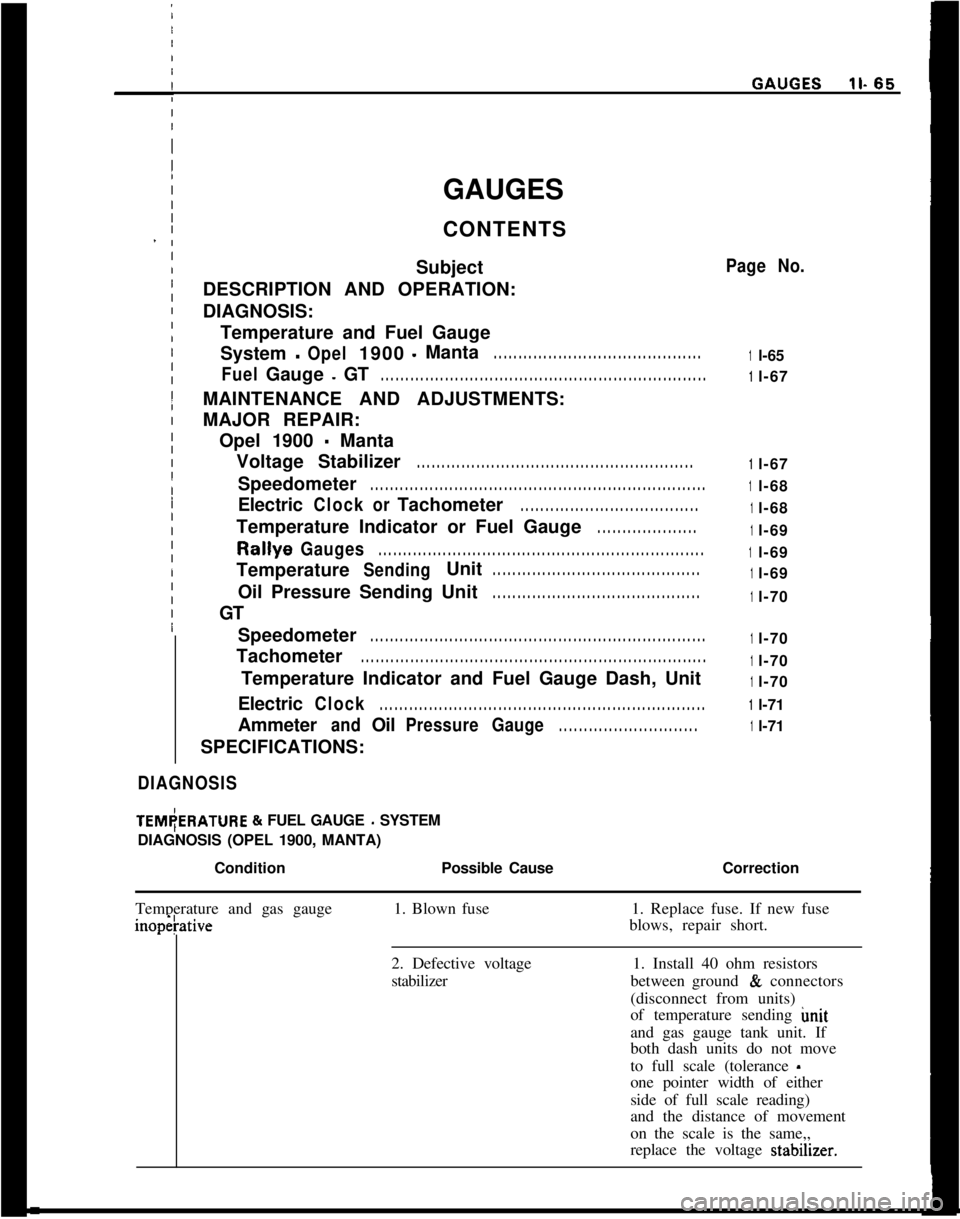
GAUGES
CONTENTS
Subject
DESCRIPTION AND OPERATION:
DIAGNOSIS:
Temperature and Fuel Gauge
System-Opel1900-Manta. . . . . . . . . . . . . . . . . . . . . . . . . . . . . . . . . . . . . . . . . .
FuelGauge-GT. . . . . . . . . . . . . . . . . . . . . . . . . . . . . . . . . . . . . . . . . . . . . . . . . . . . . . . . . . . . . . . . . .MAINTENANCE AND ADJUSTMENTS:
MAJOR REPAIR:
Opel 1900
- Manta
Voltage Stabilizer
. . . . . . . . . . . . . . . . . . . . . . . . . . . . . . . . . . . . . . . . . . . . . . . . . . . . . . . .Speedometer
. . . . . . . . . . . . . . . . . . . . . . . . . . . . . . . . . . . . . . . . . . . . . . . . . . . . . . . . . . . . . . . . . . . .Electric
ClockorTachometer. . . . . . . . . . . . . . . . . . . . . . . . . . . . . . . . . . . .Temperature Indicator or Fuel Gauge
. . . . . . . . . . . . . . . . . . . .Rallye
Gauges. . . . . . . . . . . . . . . . . . . . . . . . . . . . . . . . . . . . . . . . . . . . . . . . . . . . . . . . . . . . . . . . . .Temperature
SendingUnit. . . . . . . . . . . . . . . . . . . . . . . . . . . . . . . . . . . . . . . . . .Oil Pressure Sending Unit
. . . . . . . . . . . . . . . . . . . . . . . . . . . . . . . . . . . . . . . . . .GT
Speedometer
. . . . . . . . . . . . . . . . . . . . . . . . . . . . . . . . . . . . . . . . . . . . . . . . . . . . . . . . . . . . . . . . . . . .Tachometer
. . . . . . . . . . . . . . . . . . . . . . . . . . . . . . . . . . . . . . . . . . . . . . . . . . . . . . . . . . . . . . . . . . . . . .Temperature Indicator and Fuel Gauge Dash, Unit
Electric
Clock. . . . . . . . . . . . . . . . . . . . . . . . . . . . . . . . . . . . . . . . . . . . . . . . . . . . . . . . . . . . . . . . . .Ammeter
andOilPressureGauge. . . . . . . . . . . . . . . . . . . . . . . . . . . .SPECIFICATIONS:
DIAGNOSISITEM(ERATURE
& FUEL GAUGE - SYSTEM
DIAGNOSIS (OPEL 1900, MANTA)
/
ConditionPossible Cause
I
Page No.
1l-65
1l-67
1l-67
1l-68
1l-68
1l-69
1l-69
1l-69
1l-70
1l-70
1l-70
1l-70
1l-71
1l-71
Correction
Temperature and gas gaugeinopetative1. Blown fuse1. Replace fuse. If new fuse
blows, repair short.
2. Defective voltage
stabilizer1. Install 40 ohm resistors
between ground
& connectors
(disconnect from units)
of temperature sending imit
and gas gauge tank unit. If
both dash units do not move
to full scale (tolerance
-one pointer width of either
side of full scale reading)
and the distance of movement
on the scale is the same,,
replace the voltage stabdner.
Page 513 of 625

9A-4 1973 OPEL SERVICE MANUAL
Figure 9A-4 Heater Control
Blower Switch - This switch actuates blower motor
to low or high blower speed.
HEATER SYSTEM OPERATION
To operate heater proceed as follows:
1. Position air inlet, heater-defroster control as
desired.
White arrow head pointing down--air out of heater
outlets. White arrow head pointing up--air out of
defroster outlets.
Between lower and upper position--air to both heater
and defroster outlets.
2. Position temperature control as desired to increase
or decrease temperature of air flow.
3. Position blower switch as desired to operate
blower at low or high speed.
Dlid3NDSlS
HEATER SYSTEM TROUBLE DIAGNOSIS
TROUBLE
Temperature of heated air at outlets too low.
CAUSE AND CORRECTION
Check radiator cap for proper sealing action-- re-
place if necessary.
Check for adequate coolant supply. If level is down,
correct cause of coolant loss and refill radiator.
Inspect hose for kinks--relieve kink or replace hoses.
Check thermostat operation by measuring tempera-
ture of coolant at radiator. Temperature should be
within 5 degrees F. of thermostat rated value (189
degrees F.).
Check that air doors and water temperature control
valye are operating properly.
Check for plugged heater core--backflush heater core
as necessary.
TROUBLE
Inadequate defrosting action.
CAUSE AND COiiRECTlON
Examine heater-defroster door for proper operat-
ions--adjust bowden cable as required so that door is
fully closed in FULL DEFROST position.
Check that air hoses connecting to defroster outlets
are secure.
Check for air leaks around edges of heater air dis-
tributor housing--seal leaks as necessary with body
sealer. Check for body air leaks and seal as necessary
with body sealer.
TROUBLE
Blower inoperative.
CAUSE AND CORRECTION
Check blower fuse--replace if necessary, fuse position
3 - amperage 8.
Check wiring for open circuit--correct as required. Inspect for defective component (i.e., blower switch
or blower motor)--replace or repair as necessary.
MAINTENANCE AND ADJUSTMENTS
CONTROL CABLE ADJUSTMENT
Adjustment of control cables is accomplished by po-
sitioning of the jacket or sheath of the control cable
as held by the clamps on the control assembly and
heater case.
To adjust control cables, loosen clamps and move
cable sheath in or out as required to obtain full travel
of lever or of door or both.
Page 521 of 625

9A-i2 1973 OPEL SERVICE MANUAL
Check that air doors and water temperature control
valve are operating properly.
Check for plugged heater core-backflush heater core
as necessary.TROUBLEInadequate defrosting action.
CAUSE AND CORRECTIONExamine heater-defroster door for proper operation.
Adjust bowden cable so that door is fully closed in
FULL DEFROST position.
Check that air hoses connecting to defroster outlets
are secure.
Check for air leaks around edges of heater air dis-
tributor housing. Seal leaks, as necessary, with bodysea@. Check for body air leaks and seal, as neces-
sary, with body sealer.
TROUBLEBlower inoperative.
CAUSE AND CORRECTIONCheck blower fuse. Replace, if necessary, fuse posi-
tion 4
- amperage 15.
Check wiring for open circuit. Correct, as required.
Inspect for defective component, (i.e., blower switch
or blower motor)
- replace or repair as necessary.
MAINTENANCE AND ADJUSTMENTS
CONTROL CABLE ADJUSTMENTAdjustment of control cables is accomplished by po-
sitioning of the jacket or sheath of the control cable,
as held by the clamps on the control assembly and
heater case or by loosening screws and slidingbowden wire to obtain desired door or water valve
position.
MAJOR REPAIR
REMOVING AND INSTALLING HEATER HOUSING
Removal1. Unscrew hood lock together with ground wire(ground wire only on vehicles with radio interference
suppression). See Figure 9A-33.
Figure 9A-33 Hood Lock Attachments
2. Unscrew heater housing cover.
3. Pull hose of windshield washer system off jet and
take jet out of housing cover.
4. Unscrew bowden control wire from heater valve.
5. Unscrew heater housing from dash panel and pull
it off carefully. See Figure 9A-34.
Figure 9A-34 Heater Housing Attachments
6. Remove water hoses from heater core and pull
heater core out of heater housing. See Figure
9A-35.
Page 527 of 625

98.18 1973 OPEL SERVICE MANUAL
DESCRIPTION AND OPERATION
FUNDAMENTAL PRINCIPLES OF REFRIGERATION
We all know what air conditioning does for us, but
very few understand how or why it works. An air
conditioner is functionally very similar to a refrigera-
tor, so let’s take a look at refrigeration. A refrigerator
is a simple mechanism which, surprisingly enough,
works quite a bit like a tea-kettle boiling on a stove.
That may sound far-fetched, but there is more
similarity between the two than most of us would
suspect. In fact, a modern refrigerator can make ice-
cubes and keep food cool and fresh only because a
liquid called the refrigerant boils inside the freezer.
Of codrse everyone knows a boiling tea-kettle is
“hot” and a refrigerator is “cold”. However, this is
where most of us are apt to get confused. We usually
think of “cold” as a definite, positive condition. Ac-
tually though, there is no such thing as “cold”. The
only way we can define it is in a rather negative sort
of way by saying “cold” is simply the lack of heat
just as darkness is the lack of light. We can:t make
things cold directly. All we can do is remove some
of the heat they contain and they will become cold
as a result. And that is the main job of any ice-box
or refrigerator. Both are simply devices for removing
heat.
All substances contain some heat. Theoretically, the
lowest temperature that any substance could obtain
is 459 degrees Fahrenheit below Zero. This may be
called “Cold”, and anything warmer than this con-
tains heat. Since man has never succeeded in getting
all the heat out of an object, we must think about the
transfer of heat from one object to another when
talking about controlling temperatures.
Figure
96-1 Transfer of Heat
Transfer of HeatThe only thing that will attract heat is a colder ob-ject.
:Like water, which always flows down-hill, heat
always flows down a temperature scale
- from a
warm level down to a colder one. When we hold our
hands out toward the fireplace, heat flows from the
hot fire out to our cold hands (Fig.
9B-1). When we
make a snowball, heat always flows from our warm
hands to the colder snow. In an ice-box, the ice al-
ways is colder than the stored food, so heat naturally
is drawn out of the warm food by the colder ice.
Measurement of HeatEveryone thinks he knows how heat is measured.
Thermometers are used in most: homes. Whenever
we speak of temperature from now on, we will mean
Fahrenheit. They can tell how hot a substance is, but
they can’t tell us everything about heat.
Figure
98-2 Applied Temperature Alone is Not the
Sole Measurement of Heat
When we put a tea-kettle on a stove, we expect it to
get hotter and hotter until it finally boils. All during
the process, we can tell exactly how hot the water is
by means of a thermometer (Fig.
9B-2). However,
our thermometer will show us that the flame is just
as hot when we first put the tea-kettle on the stove
as it is when the water finally boils. Why doesn’t the
water boil immediately then? Also, why does it take
longer to boil a quart of water than a cupful? Obvi-
ously temperature isn’t the only measurement of
heat.
Even though heat is intangible, it can be measured by
quantity as well as intensity. It is recognized that
thermometers indicate only the intensity of heat. The
unit for measuring quantity of heat is specified as
that amount necessary to make 1 pound of water 1
degree warmer (Fig.
9B-3). We call this quantity of
heat a British Thermal Unit. Often it is abbreviated
to Btu.
Perhaps we can get a better idea of these two charac-
Page 532 of 625
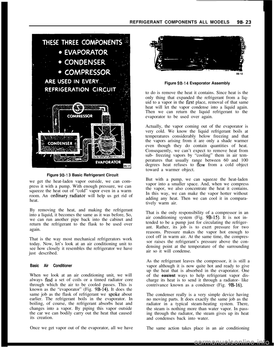
REFRIGERANT COMPONENTS ALL MODELS96.23Figure 96-l 3 Basic Refrigerant Circuit
we get the heat-laden vapor outside, we can com-
press it with a pump. With enough pressure, we can
squeeze the heat out of “cold” vapor even in a warm
room. An ordinary.radiator will help us get rid of
heat.
By removing the heat, and making the refrigerant
into a liquid, it becomes the same as it was before, So,
we can run another pipe back into the cabinet and
return the refrigerant to the flask to be used over
again.
That is the way most mechanical refrigerators work
today. Now, let’s look at an air conditioning unit to
see how closely it resembles the refrigerator we have
just described.
Basic Air ConditionerWhen we look at an air conditioning unit, we will
always find a set of coils or a tinned radiator core
through which the air to be cooled passes. This is
known as the “evaporator” (Fig.
9B-14). It does the
same job as the flask of refrigerant we
spok.e about
earlier. The refrigerant boils in the evaporator. In
boiling, of course, the refrigerant absorbs heat and
changes into a vapor. By piping this vapor outside
the car we can bodily carry out the heat that caused
its creation.
Once we get vapor out of the evaporator, all we haveFigure 98.14 Evaporator Assembly
to do is remove the heat it contains. Since heat is the
only thing that expanded the refrigerant from a liq-
uid to a vapor in the first place, removal of that same
heat will let the vapor condense into a liquid again.
Then we can return the liquid refrigerant to the
evaporator to be used over again.
Actually, the vapor coming out of the evaporator is
very cold. We know the liquid refrigerant boils at
temperatures considerably below freezing and that
the vapors arising from it are only a shade warmer
even though they do contain quantities of heat.
Consequently, we can’t expect to remove heat from
sub- freezing vapors by “cooling” them in air tem-
peratures that usually range between 60 and 100
degrees heat refuses to
flow from a cold object
toward a warmer object.
But with a pump, we can squeeze the heat-laden
vapor into a smaller space. And, when we compress
the vapor, we also concentrate the heat it contains.
In this way, we can make the vapor hotter without
adding any heat. Then we can cool it in compara-
tively warm air.
That is the only responsibility of a compressor in an
air conditioning system (Fig.
9B-15). It is not in-
tended to be a pump just for circulating the refriger-
ant. Rather, its job is to exert pressure for two
reasons. Pressure makes the vapor hot enough to
cool off in warm air. At the same time, the compres-
sor raises the refrigerant’s pressure above the con-
densing point at the temperature of the surrounding
air so it will condense.
As the refrigerant leaves the compressor, it is still a
vapor although it is now quite hot and ready to give
up the heat that is absorbed in the evaporator. One
of the easiest ways to help refrigerant vapor dis-
charge its heat is to send it through a radiator- like
contrivance known as a condenser (Fig. 9B-16).
The condenser really is a very simple device having
no moving parts. It does exactly the same job as the
radiator in a typical steam-heating system. There,
the steam is nothing more than water vapor. In pass-
ing through the radiator, the steam gives up its heat
and condenses back into water.
The same action takes place in an air conditioning