open gas tank OPEL GT-R 1973 Service Manual
[x] Cancel search | Manufacturer: OPEL, Model Year: 1973, Model line: GT-R, Model: OPEL GT-R 1973Pages: 625, PDF Size: 17.22 MB
Page 87 of 625
ll- 66 1973 OPEL SERVICE MANUALi
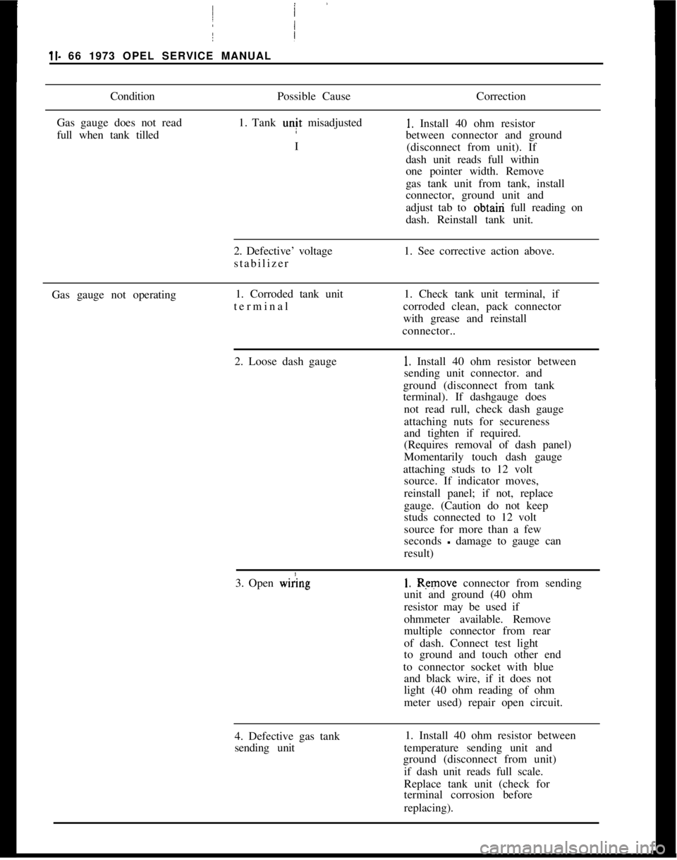
ConditionPossible CauseCorrection
Gas gauge does not read
full when tank tilled1. Tank unit misadjusted1. Install 40 ohm resistor
between connector and ground
I
(disconnect from unit). If
dash unit reads full within
one pointer width. Remove
/
Igas tank unit from tank, install
connector, ground unit and
adjust tab to obtairi full reading on
dash. Reinstall tank unit.
2. Defective’ voltage
stabilizer1. See corrective action above.
Gas gauge not operating1. Corroded tank unit
terminal I1. Check tank unit terminal, if
corroded clean, pack connector
with grease and reinstall
connector..
2. Loose dash gauge
!
1. Install 40 ohm resistor between
sending unit connector. and
ground (disconnect from tank
terminal). If dashgauge does
not read rull, check dash gauge
attaching nuts for secureness
and tighten if required.
(Requires removal of dash panel)
Momentarily touch dash gauge
attaching studs to 12 volt
source. If indicator moves,
reinstall panel; if not, replace
gauge. (Caution do not keep
studs connected to 12 volt
source for more than a few
seconds
- damage to gauge can
result)
3. Open
w&g1. Remove connector from sending
unit and ground (40 ohm
resistor may be used if
ohmmeter available. Remove
multiple connector from rear
of dash. Connect test light
to ground and touch other end
to connector socket with blue
and black wire, if it does not
light (40 ohm reading of ohm
meter used) repair open circuit.
4. Defective gas tank
sending unit1. Install 40 ohm resistor between
temperature sending unit and
ground (disconnect from unit)
if dash unit reads full scale.
Replace tank unit (check for
terminal corrosion before
replacing).
Page 88 of 625
I
GAUGES1 I- 67I
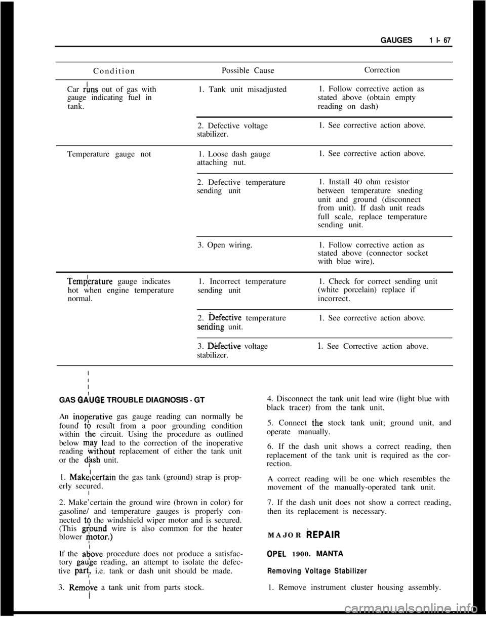
I Condition
Car
&s out of gas with
gauge indicating fuel in
tank. 1
I
I
I
I
IPossible Cause
1. Tank unit misadjusted
2. Defective voltage
stabilizer.Correction
1. Follow corrective action as
stated above (obtain empty
reading on dash)
1. See corrective action above.
Temperature gauge not1. Loose dash gauge1. See corrective action above.
Iattaching nut.
I
I
I2. Defective temperature1. Install 40 ohm resistor
Isending unitbetween temperature sneding
Iunit and ground (disconnect
I
from unit). If dash unit reads
I
full scale, replace temperature
Isending unit.
I
I
I3. Open wiring.1. Follow corrective action as
Istated above (connector socket
Iwith blue wire).Tempkrature gauge indicates
hot when engine temperature1. Incorrect temperature1. Check for correct sending unit
sending unit
normal.(white porcelain) replace if
incorrect.
2. i>efective temperaturesending unit.1. See corrective action above.
3. Dkfective voltage
stabilizer.
1. See Corrective action above.
GAS
GdUGE TROUBLE DIAGNOSIS - GT4. Disconnect the tank unit lead wire (light blue with
black tracer) from the tank unit.
An inoperative gas gauge reading can normally be
found to result from a poor grounding condition
within the circuit. Using the procedure as outlined
below may lead to the correction of the inoperative
reading without replacement of either the tank unit
or the
dph unit.5. Connect ihe stock tank unit; ground unit, and
operate manually.
6. If the dash unit shows a correct reading, then
replacement of the tank unit is required as the cor-
rection.
1. Makelcertain the gas tank (ground) strap is prop-
erly secured.A correct reading will be one which resembles the
movement of the manually-operated tank unit.
2. Make’certain the ground wire (brown in color) for
gasoline/ and temperature gauges is properly con-
nected tb the windshield wiper motor and is secured.
(This
gl?ound wire is also common for the heater
blower
etor.)7. If the dash unit does not show a correct reading,
then its replacement is necessary.
If the adove procedure does not produce a satisfac-
tory gaube reading, an attempt to isolate the defec-
tive
par<, i.e. tank or dash unit should be made.
3. Rem&e a tank unit from parts stock.MAJOR
AEPAIR
OPEL 1900. MANTA
Removing Voltage Stabilizer1. Remove instrument cluster housing assembly.
Page 165 of 625

FLVTRlJNK PLAT
DRAW BAR16x1-1/2 -DRAW‘ BAR EXTENSION-%GSAFETY CHAIN PLATE6INSTALLATION INSTRUCTIONS
1971
- 72 - 73 OPEL 1900 SERIES S/W
GROUP NO. 7.068
REMOVE LICENSE PLATE
STEP 1. ASSEMBLE HITCH AS ILLUSTRATED. HOLD
HITCH IS POSITION WITH FLOOR PLATE RESTING
AGAINST THE CROSS FRAME IN FRONT OF GAS TANK.
CENTER DRAW BAR SUPPORT ON THE REAR BODY
PANEL, RAISE UNTIL LEVEL.
STEP 2.MARK AND DRILL TWO
7116” HOLES IN REAR
BODY PANEL AND ATTACH AS SHOWN.
STEP 3.DRILL TWO
112” HOLES IN CROSS FRAME IN
FRONT OF THE GAS TANK AND CONTINUE DRILLING UP
THROUGH THE INNER FLOOR. NOTE: HOLD DRILL
VERTICAL WHILE DRILLING THROUGH THE INNER FLOOR.
ENLARGE BOTTOM HOLE SLIGHTLY TO ACCEPT SPACER.
STEP 4. ATTACH TRUNK PLATE AS ILLUSTRATED. PLACE
THE FLOOR PLATES ON THE 2
l/2” CARRIAGE BOLTS
AND INSERTS THROUGH THE OPENINGS
iN THE BACK OF
THE TRUNK WELL.INSERT SPACERS AS SHOWN AND
COMPLETE INSTALLATION.
REPLACE LICENSE PLATE.
TIGHTEN ALL
112” NUTS TO A MAXIMUM TORQUE OF
60 FOOT LBS. AND 7/16” NUTS TO A MAXIMUM OF
45 FOOT LBS.
INSTALL BALL USING A MAXIMUM TORQUE OF 150
FOOT LBS.
MAXIMUM GROSS WEIGHT 100 LBS
MAXIMUM TONGUE WEIGHT 100 LBS.
MOST STATES PROHIBIT OBSTRUCTION OF LICENSE
PLATES, BALL SHOULD BE REMOVED WHEN NOT IN
USE IF IT OBSTRUCTS A CLEAR VIEW.
ZH-9Figure
ZH-9 Opel 1900 Wagon Trailer Hitch Installation
Page 325 of 625

6B- 341973 OPEL SERVICE MANUAL
test by partially draining the cooling system and dis-
connecting the water outlet housing from the ther-
mostat housing which is mounted on the right front
side of cylinder head.
The standard thermostat valve should start to open
at 189 degrees F and fully open at approximately 212
degrees F. If thermostat does not operate at specified
temperatures, it should be replaced as it cannot be
repaired.MAJOR REPAIR
WATER PUMP REPAIRSThe water pump bearing outer race is shrunk fit into
the water pump cover. For this reason the cover,
shaft bearing, and hub are not repairable.
Water Pump RemovalOpel radiators do not have a drain plug. Drain radia-
tor by first, loosening radiator cap, then remove
lower hose from lower radiator tank.
1. Drain coolant into a clean container. Remove
radiator and shroud.
2. Remove fan belt.
3. Remove fan blade and pulley on water pump shaft.
4. Disconnect inlet hose and heater hose from water
pump. Remove bolts, pump assembly and gasket
from timing chain cover.
5. Check pump shaft bearing for end play or rough-
ness in operation. If bearings are not in serviceable
condition, the assembly must be replaced.
Water Pump Installation1. Make sure the gasket surfaces on pump and timing
chain covers are clean. Install pump assembly with
new gasket. Bolts must be tightened uniformly.
Torque to 11 lb. ft.
2. Install radiator and shroud. Connect radiator hose
to pump inlet and heater hose to nipple.
3. Install fan pulley and fan blade, tighten attaching
bolts securely. Install belts and adjust for proper
tension.4. Fill cooling system and check
,for leaks at pump
and hose joints.
RADIATOR REMOVAL AND INSTALLATION
RemovalI. Loosen radiator cap, then remove lower radiator
hose and drain radiator coolant into suitable con-
tainer.
2. On vehicles with automatic transmission, unscrew
oil lines from connectors on lower radiator tank and
plug lines. On GT models with automatic transmis-
sion the lines have to be disconnected at the coupling
before removing from the tank. It is essential that no
dirt enters the oil lines. When unscrewing oil lines,
hold connectors on lower radiator tank with pliers to
avoid leakages. Ensure that no dirt enters oil cooler.
3. Remove lower attaching nut and slide radiator
upward and out of engine compartment.
Installation1. Install radiat,or into engine compartment and se-
cure lower attaching nut.
2. On vehicles with automatic transmissions, fasten
oil cooler lines to lower radiator tank. It is essential
that no dirt enters the oil lines. When tightening oil
lines, hold connectors on lower radiator tank with
pliers to avoid leakages. Ensure that no dirt enters oil
cooler. Torque to 1 I-15
lbs.ft.3. Install lower radiator hose and add collected coo-
lant.
All Opels are provided with a radiator initial fill of
an antifreeze solution containing corrosion inhibitor.
The antifreeze has either a glycol or glycerin base
and protects the engine against freezing, down to
minus 22 degrees F. (minus 30 degrees C.). Before
the start of the cold season, coolant must be checked
with a hydrometer and if necessary, brought to the
necessary specific gravity by adding anti-freeze with
a glycol or glycerin base. As the specific gravities of
all anti- freeze solutions having a glycol or glycerin
base are practically the same, the hydrometer can be
used for all these types. Because of the tolerances of
the hydrometer, or slight differences in specific
gravity, variations of plus or minus 5 degrees can be
expected. Coolant must be checked at a temperature
of plus 68 degrees F. (plus 20 degrees C.)
Page 329 of 625
6C- 381973 OPEL SERVICE MANUALCAUTION:Because the fuel pump is below fuel tank
level, fuel
will drain from the tank. when the supply
hne is disconnected from the fuel pump.1. Pull fuel supply line and rubber connector from
fuel pump. Plug rubber connector to prevent fuel
loss.2. Remove fuel pump cap, gasket and plastic
strainer.
3. Cover center opening in sediment bowl with finger
and blow out sediment bowl with compressed air.
4. Wash plastic strainer in solvent; if strainer does
not clean-up or is damaged, replace strainer.
5. Install clean parts, noting the following:
(a) Strainer must be properly seated with projections
facing upward.(b) A new cap gasket must be positioned over
strainer.
(c) Sealing ring must be in place on cap retaining
screw.6. Reconnect fuel supply line. Start engine and check
for leaks.
EVAPORATION CONTROL SYSTEMProper performance of the system requires the use of
a non-vented fuel tank cap, hose connections be leak-
free, and all hoses routed correctly to avoid a
pinched or blocked line.
Maintenance requirements demand only that the ac-
cumulator purge air tilter, an oiled foam filter assem-
bled in the bottom of the canister, be replaced at
12,CKO mile intervals. Under extremely dusty condi-
tions, more frequent attention may be required.
Figure
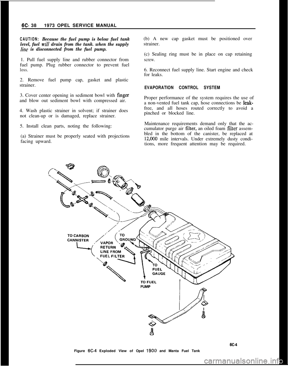
W-4 Exploded View of Opel 1900 and Manta Fuel Tank
Page 534 of 625
REFRIGERANT COMPONENTS ALL MODELS9B- 2596.15
Figure 95.17 Float Type Flow Valve
enough to close the valve and stop the flow of refrig-
erant liquid.
For the sake of simplicity, we have described the
float and valve action as being in a sort of definite
wide open or tight shut condition. Actually, though,
the liquid level falls rather slowly as the refrigerant
boils away. Likewise, the float goes down gradually
and gradually opens the valve just a crack. New
refrigerant liquid barely seeps in through the
“cracked” valve. At such a slow rate of flow, it raises
the liquid level in the evaporator very slowly.
With that in mind, it is easy to see how it would be
possible for a stabilized condition to exist. By that,
we mean a condition wherein the valve would be/
DIAPHRAGMACTUATINGBACK.UP PLATE
PINS \
t
>IAPHRAGM \
/
BoDyEQUALIZER\4]
PASSAGE
‘!!!ISEATSCkEEN:ARRIAGEORIFICE
AGE SPRINGIER ELEMENT:MOB”LBSPRING SEAT
OUTLET
W-16opened barely enough to allow just exactly the right
amount of refrigerant liquid to enter the freezer to
take the place of that leaving as a vapor.
Thermostatic Expansion ValveAutomotive air conditioning systems use a thermo-
static expansion valve in place of the float system.
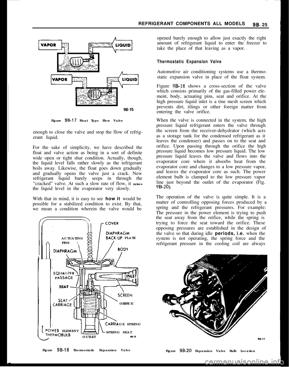
Figure 9B-18 shows a cross-section of the valve
which consists primarily of the gas-filled power ele-
ment, body, actuating pins, seat and orifice. At the
high pressure liquid inlet is a tine mesh screen which
prevents dirt, tilings or other foreign matter from
entering the valve orifice.
When the valve is connected in the system, the high
pressure liquid refrigerant enters the valve through
the screen from the receiver-dehydrator (which acts
as a storage tank for the condensed refrigerant as it
leaves the condenser) and passes on to the seat and
orifice. Upon passing through the orifice the high
pressure liquid becomes low pressure liquid. The low
pressure liquid leaves the valve and flows into the
evaporator core where it absorbs heat from the
evaporator core and changes to a low pressure vapor,
and leaves the evaporator core as such. The power
element bulb is clamped to the low pressure vapor
line just beyond the outlet of the evaporator (Fig.
9B-20).The operation of the valve is quite simple. It is a
matter of controlling opposing forces produced by a
spring and the refrigerant pressures. For example:
The pressure in the power element is trying to push
the seat away from the orifice, while the spring is
trying to force the seat toward the orifice. These
opposing pressures are established in the design of
the valve so that during idle periods, i.e. when the
system is not operating, the spring force and the
refrigerant pressure in the cooling coil are always
Figure 9B-18 Thermostatic Expansion Valve
Figure
98.20 Expansion Valve Bulb Location
Page 540 of 625
REFRIGERANT COMPONENTS ALL MODELS9B- 31
When adding oil, the container should be exception-
ally clean and dry due to the fact that the refrigera-
tion oil in the container is as moisture-free as it is
possible to make it. Therefore, it will quickly absorb
any moisture with which it comes in contact. For this
same reason the oil container should not be opened
until ready for use and it should be capped immedi-
ately afte;r use.
When it is necessary to open a system, have every-
thing you will need ready and handy so that as little
time as possible will be required to perform the oper-
ation. Don’t leave the system open any longer than
is necessary.
Finally, after the operation has been completed and
the system sealed again, air and moisture should be
evacuated from the system before recharging.
THE PRIMARY CAUSES OF SYSTEM FAILURES
LeaksA shortage of refrigerant causes oil to be trapped in
the evaporator. Oil may be lost with the refrigerant
at point of leakage. Both of these can cause compres-
sor seizure.
Oil circulates in the system with the refrigerant; in
solution with the liquid and in globules with the
vapor. It leaves the compressor by the action of the
pistons and mixes with the refrigerant liquid in the
condenser. The oil then enters the evaporator with
the liquid and, with the evaporator properly flooded,
is returned to the compressor through the low pres-
sure line. Some of the oil returns as globules in the
vapor, but more important, it is swept as a liquid
along the walls of the tubing by the velocity of the
vapor. If the evaporator is starved, the oil cannot
return in sut?icient quantities to keep the compressor
properly lubricated.
High Temperature and PressureAn increase in temperature causes an increase in
pressure. This accelerates chemical instability due to
existing contaminants in the system, and initiates
chemical instability in clean systems. Other results
are brittle hoses,
“0” ring gaskets, and valve dia-
phragms with possible decomposition, broken com-
pressor discharge reeds, and seized compressor
bearings.
A fundamental law of nature accounts for the fact
that when a substance, such as a refrigerant, is in-
creased in temperature, its pressure is also increased.
Any chemical reactions caused by contaminants al-
ready in the system are greatly accelerated as the
temperature increases. A 15 degree rise in tempera-
ture doubles the chemical action. Even in a goodclean system, heat alone can start a chain of harmful
chemical reactions.
While temperature alone can cause the synthetic rub-
ber parts to become brittle and possibly to decom-
pose, the increased pressure can cause them to
rupture or blow.
As the temperature and pressure increases the stress
and strain on the compressor discharge reeds also
increases. This can result in broken reeds. Due to the
effect of the contaminants caused by high tempera-
ture and pressure, compressor bearings can be
caused to seize.
High temperature and pressure are also caused by air
in the system.
Air in the SYstemAir results from a discharged system or careless ser-
vicing procedures. This reduces system capacity and
efficiency and causes oxidation of oil into gum and
varnish.
When a leak causes the system to become dis-
charged, the resulting vacuum within the system will
cause air to be drawn in. Air in the system is a
non-condensable gas and will build up in the con-
denser as it would in an air compressor tank. The
resultant heat produced will contribute to the condi-
tions discussed previously.
Many systems are contaminated and also reduced in
capacity and efficiency by servicemen who either do
not know or are careless regarding proper servicing
procedures.
Too frequently, systems which have been open to the
atmosphere during service operations have not been
properly purged or evacuated. Air is also introduced
into the system by unpurged gauge and charging
lines. Remember that any air in the system is too
much air.
Poor ConnectionsHose clamp type fittings must be properly made.
Hoses should be installed over the sealing flanges and
with the end of the hose at the stop flange. The hose
should never extend beyond the stop flange. Locate
the clamp properly and torque as recommended. Be
especially careful that the sealing flanges are not
nicked or scored or a future leak will result.
When compression fittings are used, over tightening
can cause physical damage to the “0” ring gasket
and will result in leaks. The use of torque and back-
ing wrenches is highly recommended. When making
a connection with compression fittings, the gaskets
should always be first placed over the tube before