service indicator OPEL GT-R 1973 Service Manual
[x] Cancel search | Manufacturer: OPEL, Model Year: 1973, Model line: GT-R, Model: OPEL GT-R 1973Pages: 625, PDF Size: 17.22 MB
Page 19 of 625
CC-10 1973 OPEL SERVICE MANUAL
wiper blades. Check amount and direction of fluid
sprayed by washers during use.,
E. Defrosters - Check performance by moving con-
trols to “DEF” and noting
am$nmt of air directed
against the windshield.
I
F. Wheel Alignment and
Balabce - In addition to
abnormal tire wear, the need fbr wheel alignment
service may be indicated by a pull to the right or
!eftwhen driving on a straight and level road. The need
for wheel balancing is usually
iddicated by a vibra-
tion of the steering wheel or
se;+ tihile driving at
normal highway speeds.I
IG. Brakes
- Be alert to illumiriation of the brake
warning light or changes in braking action,
SUCK as
repeated pulling to one side, unusual sounds when
braking or increased brake pedal travel. Any of thesecould indicate the need for
brakk system inspection
and/or service.
H. Parking Brake and Transmission “PARK”
Mechanism
- Check parking brake holding ability by
parking on a fairly steep hill and restraining the vehi-
cle with the parking brake only.
eon cars with auto-
matic transmissions, check the holding ability of the
“PARK” mechanism by releasing all brakes after
the transmission selector lever hak been placed in the“P” position.
I. Glass
- Check for broken, scrritched, dirty or da-
maged glass on vehicle that
coulld obscure vision’or
become an injury hazard.
J. Lights and Buzzers
- Check all instrument panel
illuminating and warning lights,’ seat belt reminder
light and buzzer, ignition key
b&er, interior lights,
license plate lights, side marker! lights, headlamps,
parking lamps, tail lamps, brake lights, turn signals,
backup lamps, and hazard warding flashers. Have
someone observe operation of
&ach exterior light
while you activate the controls: The operation of
instrument panel warning lights is covered in the
“Starting and Operating“ section of your
Own&%
Manual.K. Transmission Shift Indicator
‘- Check to be sure
automatic transmission shift
indiCator accurately i”-
dicates the shift position selected.
I
CAUTION: Before making thk check below,I
be sure to have a clear dist&e ahead and:
behind the car, set the parking brake and
firmly apply the foot brake.
Do not depress
accelerator pedal. Be prepared to
turn off ’
ignition switch
immediat+y if engine
should start.L. Starter Safety Switch (Automatic Transmissibn
Cars)
- Check starter safety switch by placing the
transmission in each of the driving gears while
at-tempting to start the engine. The starter should oper-ate only in the Park (“P”) or Neutral (“N”)
positions.
M. Horn
- Blow the horn occasionally to be sure thatit works. (Ignition switch must be in the “ON” posi-
tion.)
N. Seat Back Latches
- Check to see that seat back
latches are holding by pulling forward on the top of
each folding seat back.
0. Rearview Mirrors and Sun Visors
- Check that
friction joints are properly adjusted so mirrors and
sun visors stay in the selected position.
P. Door Latches
- Check for positive closing, latch-
ing and locking.
Q. Hood Latches - Check to make sure hood closesfirmly by pressing on the hood at the latching point
after each closing. Check also for broken, damaged
or missing parts which might prevent secure latch-
ing.R. Fluid Leaks
- Check for fuel, water, oil or other
fluid leaks by observing the ground beneath the vehi-cle after it has been parked for a while. If gasoline
fumes or fluid are noticed at any time, the cause
should be determined and corrected without delay
because of the possibility of fire.
S. Exhaust System
- Be alert to any change in the
sound of the exhaust system or a smell of fumes
which may indicate a leak.
Head Restraints
- Check that no head restraint
components are missing, damaged or loose. (Does
not apply to GT Models).
Disc BrakesCheck brake pads and condition of rotors while
wheels are removed during tire rotation. (Note belowregarding more frequent checks also applies to disc
brakes.)
Parking and Drum BrakesCheck drum
brake linings and other internal brake
components at each wheel (drums, wheel cylinders,
etc.). Parking brake adjustment also should be
checked whenever drum brake linings are checked.
NOTE: More frequent checks should be
made if driving conditions a.nd habits result
in frequent brake application. When brakes
require relining, it is recommended thatyou use those genuine General Motors
parts specified for your car,and Delco fluid
as required.
Page 28 of 625
BATTERY AND CABLES - ALL MODELSlA- 7
421 Test
F$ocedure1. Visual Inspection
- The first step in testing the
Energizer br 12-V& Battery should be a visual in-
spection
which very often will save time, labor and
expense in determining the condition.
(a) Check for broken or cracked case or cover.
(b) Check ,for loose terminal posts.
fiozeck Ifor defective or mutilated sealing com-(d) Check for other visible signs of physical damage.
Obvious d?mage as a result of conditions described
above indicates the need for Energizer or batteryreplaceme$t.
2. The “421” Test is a programmed test procedure
consisting bf a series of timed discharge and charge
events, reqtdring approximately 2 to 3 minutes, that
will determine the condition of the Energizer or bat-
tery with a high degree of accuracy when used inconjunctioti with this entire test procedure. “421”
Testers
a$ produced by a number of different manu-
facturers
r+nd their directions for tester operation
should be carefully followed. General comments on
overall “42 1” Tester operation follow:
(a) Energi@rs or batteries should
nor be charged
prior to
making this test. Defects within the unit can
be hidden by the charging and erroneous test results
will be obtpined.
(b) Erratic, or extremely low, initial meter readings
may indicate poor connections at the tester termi-
nals.Obt{in clean and tight connections beforeper-
forming the 421
Test.(c) All meter readings should be made immediately
after the meter indicator light comes on even if the
meter needle is still moving.
(d) If additional discharges are required after the
initial discbarge, set meter indicator following thefast discharge cycle.
(e) Batteries designated as “bad” by the tester should
be replaced.
(f) Batteries designated as “good” with no owner’s
complaint or indication of poor performance, should
be left in s+vice. Posts, cable clamps, and top should
be cleaned, water should be added and recharging
should be
,performed, if required. For dependable
and reliable battery service, the battery should be in
at least a
75 per cent state-of-charge.
(g) Batteries designated as “good” that are suspected
of being questionable because of owner complaint, orage of the battery, should be further tested by the
Hydrometer Test.
HYDROMETER TEST OF BATTERY
The 421 Battery Test as described in the previous
paragraph is the fastest and most accurate means of
determining the serviceability of a one-piece cover
battery. However, ifa 421 Battery Tester is not avail-
able, a hydrometer test may be used on a battery that
has failed to give proper service.
Hydrometer Test1. Fully charge battery.
2. Measure specific gravity of each cell as described
in sub-paragraph below.
Decide battery serviceability as follows:
(a) If all cells read between 1.230 and 1.310, the
battery is okay. All it needed was a full charge.
(b) After fully charging battery, if any cell reads less
than 1.230, the battery is defective and should be
replaced.
Use of HydrometerThe Hydrometer measures the percentage of sulphu-
ric acid in the battery electrolyte in terms of specific
gravity. As a battery drops from a charged to a dis-
charged condition, the acid leaves the solution and
enters the plates, causing a decrease in specific
gravity of electrolyte. With a hydrometer, an indica-
tion of the concentration of the electrolyte is ob-
tained.
The specific gravity of the electrolyte varies not only
with the percentage of acid in the liquid, it also varies
with temperature. As temperature increases, the
electrolyte expands so that the specific gravity is re-
duced. As temperature drops, the electrolyte con-
tracts so that the specific gravity increases. Unless
these variations in specific gravity are taken into
account, the specific gravity obtained by the hy-
drometer may not give a true indication of the con-
centration of acid in the electrolyte.
Correction can be made for temperature by adding
,004, usually referred to as 4 “points of gravity”, to
the hydrometer reading for every 10 degrees F. that
the electrolyte is above 80 degrees F. or subtracting004 for every 10 degrees F. that electrolyte is below
80 degrees F. Figure IA-4 shows the exact correctionfigure to use for any temperature above or below 80
degrees F., the three steps used in obtaining the cor-
rected or true specific gravity, and two examples
showing how it is figured.
Page 67 of 625
1F. 46 1973 OPEL SERVICE MANUAL
’
/
Headlight High-Low Beam Control and Passing:
SignalI
When the headlights have been switched on, high
and low beam selection is made by raising the direc-
tional signal lever toward steering wheel. Each
ti&the lever is raised, beam position, will change.
When the headlights are not on, a flashing headlight
signal may be given by raising and lotiering the di-
rectional signal lever. With the headlights on and
inlow beam position, raising and lowering the direc-
tional signal lever will also cause the headlights to
flash.
Fog Light SwitchAll Rallye models are equipped with two white f?g
lights mounted below the front bumper.
The fog light toggle switch is located on the
insty-ment cluster to the left of the temperature and
fuelgauge cluster.
/
The fog lights can be turned off at any time by the
toggle switch, but can only be tyrned on when: :
1. The ignition switch on or the
?gine running.!
2. The fog light toggle switch lower half is pushed
in.3. The parking lights and/or low beam headlights
are
OKThe fog lights are automatically turned off if the
ignition switch is on and the headlights are switched
to high beam position.
Courtesy LightThe courtesy light illuminates the interior of the Car
when any door is opened. The courtesy light can also
be turned on with all doors closed by tilting the l&s.
GT Headlamp MechanismThe concealed headlamps are moved mechanically.
Pushing actuating lever on left side of console opens
headlamps and pulling lever closes headlamps. Two
(2) meshing gear segments convert the movement, of
the lever to a rotation of 180 degrees. The pivots of
the headlamps lie below the centerline so that with
headlamps in closed position, the headlamp housing
is flush with front sheet metal. Refer to Group 110,
Section “F”, for service procedures on the GT head-
lamp mechanism.
A white indicator lamp in the instrument panel lights
if the headlamps are not completely opened lorclosed The switches of the headlamp electrical sys-
tem are located behind the left headlamp operating,
mechanism.
MAINTENANCE AND ADJUSTMENTSHEADLAMP AIMING
The headlamps must be properly aimed in order to
obtain maximum road illumination and safety that
has been built into the headlighting equipment. With
the Guide T-3 type sealed beam units, proper aiming
is even more important because the increased range
and power of this lamp make even slight variations
from recommended aiming hazardous to approach-
ing motorists. The headlamps must be checked for
proper aim whenever a sealed beam unit is replaced
and after an adjustment or repairs of the front end
sheet metal assembly.
Regardless of method used for checking headlamp
aim, car must be at normal weight, that is, with gas,
oil, water, and spare tire. Tires must be uniformly
inflated to specified pressure. If car will regularly
carry an unusual load in rear compartment, or a
trailer, these loads should be on car when headlamps
are checked. Some States have special requirements
for headlamp aiming adjustment, and these require-
ments should be known and observed.
Horizontal and vertical aiming of each seal beam
unit is provided by two adjusting screws which move
the mounting ring in the body against the tension of
the coil spring. There is no adjustment for focus,
since the sealed beam unit is set for proper focus
during manufacturing assembly.
MAJOR REPAIRHEADLIGHT SWITCH
- OPEL 1900. MANTA
Removal1. Remove instrument cluster cover panel. See Sec-
tion H.
2. Compress retaining springs and pull switch out.
See Figure 1 F-
1.3. Pull multiple socket off switch.
Installation
1: Plug multiple socket in switch and push switch in
panel until clips lock in place.
2. Replace instrument cover and secure with two (2)
screws.
Page 77 of 625
:lG- 56 1973 OPEL SERVICE MANUAL
I
FUSEqOSlTlON
1
2
3
4
5
6AMPS.
5
5
8
15
15
8ClRClJlT$ PROTECTED
OPEL 1900
& ‘MANTA (51,53,54,57,57R)
LEFT PARkING LIGHT,
LEFTTAIL LIGHT, LEFTSIDE
MARKER LIGHTS
RIGHT PApKING LIGHT, RIGH TAIL LIGHT, RIGHT
SIDE MARKER LIGHTS, INSTRUMENT PANEL LIGHTS,
SHIFT GUADRANT LIGHTS, LICENSE PLATE LIGHT,
FOG LIGHTS (RALLYE ONLY)
IGNITION IKEY
WARNIN BUZZER, TRUNK LIGHT,
HAZARD WARNING FLA,SHER, COURTESY LIGHT, CLOCK
BACKUP L’IGHTS, BLOWER MOTOR, CIGAR LIGHTER; RADIO,
SAFETY BELT WARNING BUZZER AND LIGHT
WINDSHIELD WIPERS, WINDSHIELD WASHER (RALLYE
ONLY), HORN
STOP LIGtiTS,TURN
SlGsNAL AND INDICATOR LIGHT,
PARKING BRAKE WARNING AND BRAKE FAILURE LIGHT,
FUEL GAGE, TEMPERATURE GAGE, OIL PRESSUREINDICATGR LIGHT. CHARGING INDICATOR~LIGHT,
TACHOMETER AND OIL PRESSURE GAGE (RALLYE ONLY)
AIR CONDITIONING
- 20 AMP INLINE F:USE
8
5
16
5OPEL GT
(77)WINDSHIELD WIPERS, WINDSHIELD WASHER, HORN, BACKUP
LIGHT, SP;FETY BELT WARNING BUZZER AND LIGHT
STOP LIGHTS, TURN SIGNAL AND INDICATOR LIGHT,
PARKING BRAKE WARNING LIGHT (AUTOMATIC ONLY),
BRAKE FAILURE WARNING LIGHT, RADIO, TACHOMETER,
OIL PRESiURE GAGE
& INDICATOR LIGHT, FUEL GAGE,
TEMPERATURE GAGE, CHARGING INDICATOR LIGHT
CIGAR LIGHTER, BLOWER MOTORIGNITION~KEY WARNING BUZZER, COURTESY LIGHT, CLOCK,
HAZARD WARNING FLASHER
LEFT PARKING LIGHTS, LEFT TAIL LIGHT, LEFT REAR
SIDE MAdKER LIGHT
RIGHT PA’RKING LIGHTS, RIGHT TAIL LIGHT, RIGHT REAR
SIDE MAdKER LIGHT
INSTRUMENT PANEL LIGHTS, LICENSE PLATE LIGHT.
SHIFT QUADRANT LIGHT
AIR CON,DlTlONlNG
-A/C HAS A 20 AMP INLINE FUSE AND IS
CONNECTED TO THE HOTSIDE OF FUSE NO. 23OlG3
Page 79 of 625
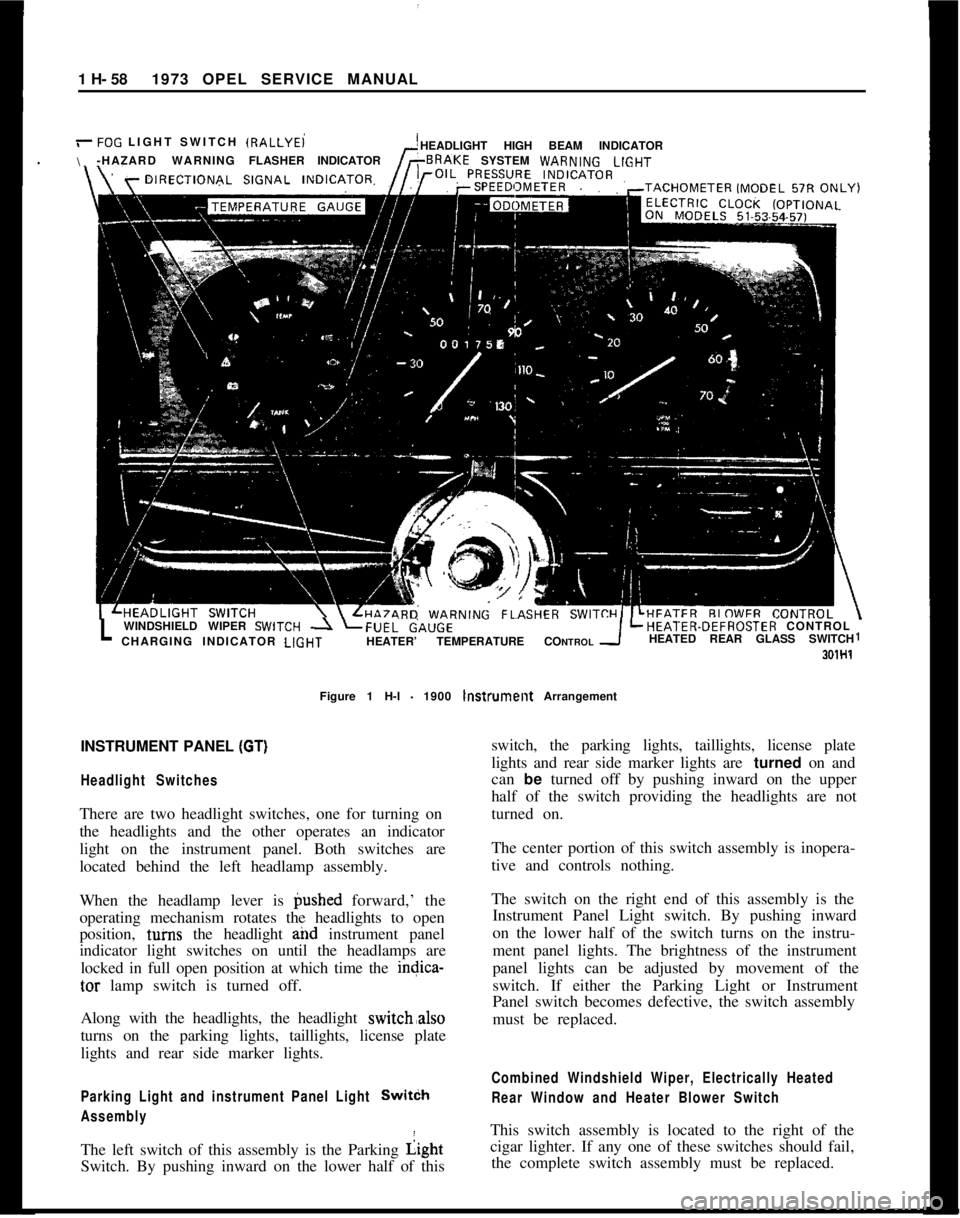
1 H- 581973 OPEL SERVICE MANUAL
/-FOG LIGHT SWITCH IRALLYEi
\HEADLIGHT HIGH BEAM INDICATOR
-HAZARD WARNINGFLASHERINDICATORSYSTEM WARN,NGLlGHT
LWINDSHIELD WIPER SWlTCH -1 LFUEL&,UGELHEATER-DEFROSTER CONTROL
CHARGING INDICATOR LlGHTHEATER’ TEMPERATURE CONTROLHEATED REAR GLASS SWITCH1
301H1Figure 1 H-l
- 1900 lnstrumellt Arrangement
INSTRUMENT PANEL
(GT)I
Headlight SwitchesThere are two headlight switches, one for turning on
the headlights and the other operates an indicator
light on the instrument panel. Both switches are
located behind the left headlamp assembly.
When the headlamp lever is @shed forward,’ the
operating mechanism rotates the headlights to open
position, tuins the headlight and instrument panel
indicator light switches on until the headlamps are
locked in full open position at which time the indica-
tar lamp switch is turned off.
Along with the headlights, the headlight switch,also
turns on the parking lights, taillights, license plate
lights and rear side marker lights.
Parking Light and instrument Panel Light SwitCh
AssemblyThe left switch of this assembly is the Parking Light
Switch. By pushing inward on the lower half of thisswitch, the parking lights, taillights, license plate
lights and rear side marker lights are turned on and
can be turned off by pushing inward on the upper
half of the switch providing the headlights are not
turned on.
The center portion of this switch assembly is inopera-
tive and controls nothing.
The switch on the right end of this assembly is the
Instrument Panel Light switch. By pushing inward
on the lower half of the switch turns on the instru-
ment panel lights. The brightness of the instrument
panel lights can be adjusted by movement of the
switch. If either the Parking Light or Instrument
Panel switch becomes defective, the switch assembly
must be replaced.
Combined Windshield Wiper, Electrically Heated
Rear Window and Heater Blower SwitchThis switch assembly is located to the right of the
cigar lighter. If any one of these switches should fail,
the complete switch assembly must be replaced.
Page 87 of 625
ll- 66 1973 OPEL SERVICE MANUALi
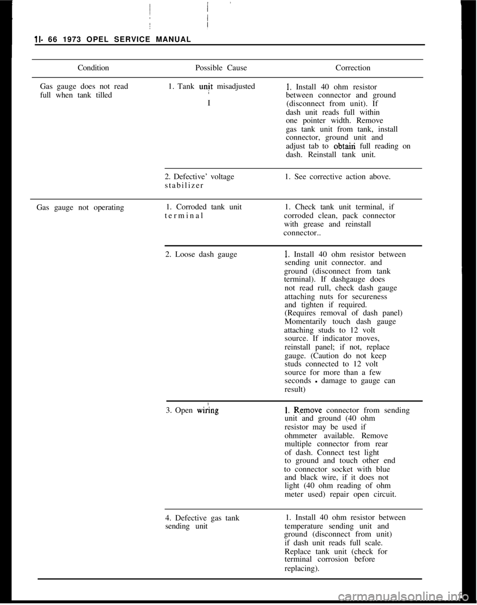
ConditionPossible CauseCorrection
Gas gauge does not read
full when tank tilled1. Tank unit misadjusted1. Install 40 ohm resistor
between connector and ground
I
(disconnect from unit). If
dash unit reads full within
one pointer width. Remove
/
Igas tank unit from tank, install
connector, ground unit and
adjust tab to obtairi full reading on
dash. Reinstall tank unit.
2. Defective’ voltage
stabilizer1. See corrective action above.
Gas gauge not operating1. Corroded tank unit
terminal I1. Check tank unit terminal, if
corroded clean, pack connector
with grease and reinstall
connector..
2. Loose dash gauge
!
1. Install 40 ohm resistor between
sending unit connector. and
ground (disconnect from tank
terminal). If dashgauge does
not read rull, check dash gauge
attaching nuts for secureness
and tighten if required.
(Requires removal of dash panel)
Momentarily touch dash gauge
attaching studs to 12 volt
source. If indicator moves,
reinstall panel; if not, replace
gauge. (Caution do not keep
studs connected to 12 volt
source for more than a few
seconds
- damage to gauge can
result)
3. Open
w&g1. Remove connector from sending
unit and ground (40 ohm
resistor may be used if
ohmmeter available. Remove
multiple connector from rear
of dash. Connect test light
to ground and touch other end
to connector socket with blue
and black wire, if it does not
light (40 ohm reading of ohm
meter used) repair open circuit.
4. Defective gas tank
sending unit1. Install 40 ohm resistor between
temperature sending unit and
ground (disconnect from unit)
if dash unit reads full scale.
Replace tank unit (check for
terminal corrosion before
replacing).
Page 93 of 625
1 J- 72 1973 OPEL SERVICE MANUAL
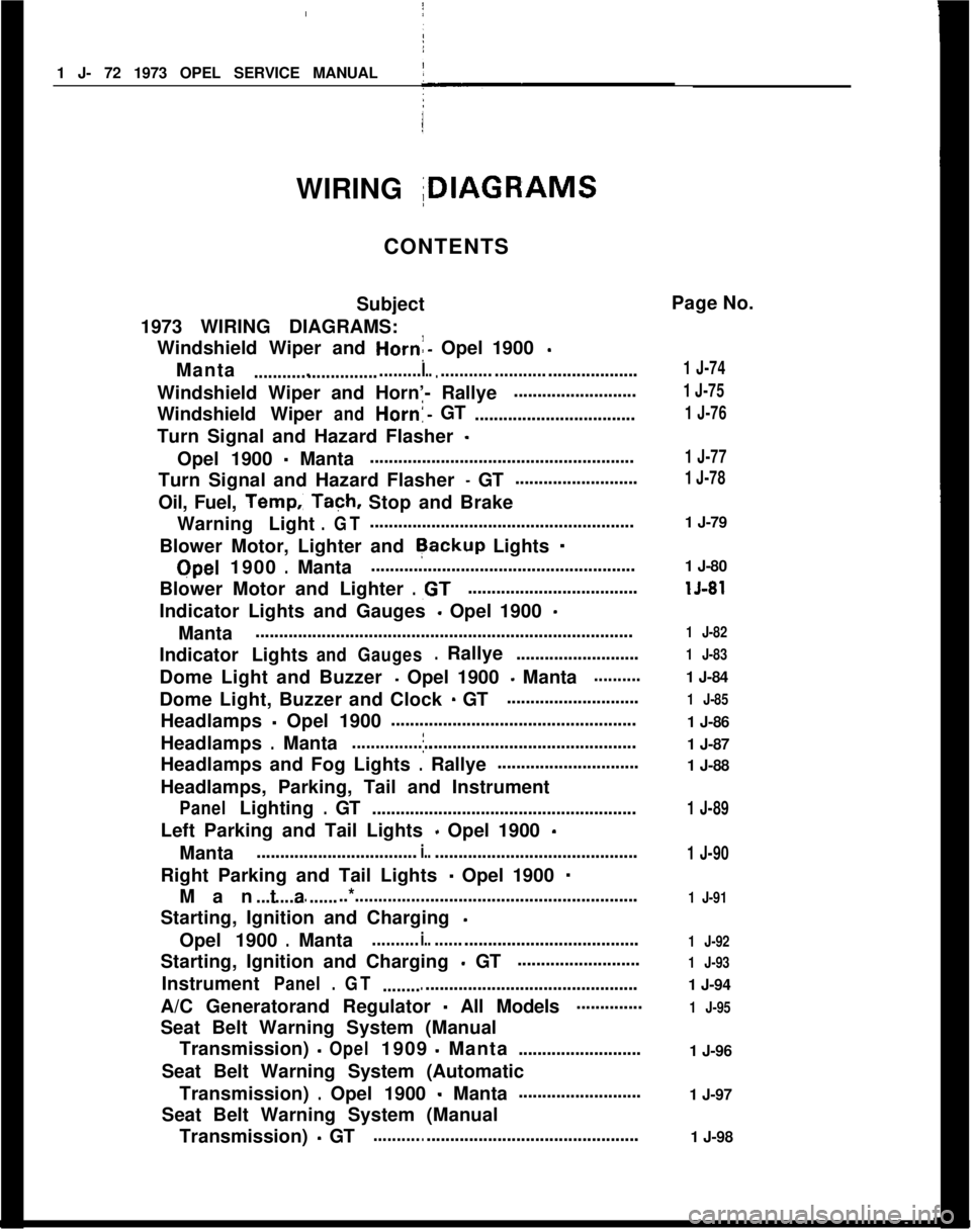
I
WIRING IDIAGRAMS
CONTENTS
Subject
1973 WIRING DIAGRAMS: Windshield Wiper and
Horn:- Opel 1900 -
Manta....................................I.............. ..............................
Windshield Wiper and Horn’- Rallye ..........................
Windshield Wiper
andHorn!-GT
..................................
Turn Signal and Hazard Flasher
-
Opel 1900 - Manta !
........................................................
Turn Signal and Hazard Flasher
- GT ..........................
Oil, Fuel,
Temp.: Tach, Stop and Brake
Warning Light
.GT........................................................
Blower Motor, Lighter and
Rackup Lights -
Qpel 1900.Manta ........................................................
Blower Motor and Lighter
.,GT....................................
Indicator Lights and Gauges
- Opel 1900 -
Manta ........................................................................\
........
Indicator Lights
andGauges.Rallye ..........................
Dome Light and Buzzer
- Opel 1900 - Manta..........
Dome Light, Buzzer and Clock - GT ............................
Headlamps
- Opel 1900 ’
....................................................
Headlamps
.Mantaj............................................................
Headlamps and Fog Lights
.Rallye ..............................
Headlamps, Parking, Tail and Instrument
PanelLighting.GT ........................................................
Left Parking and Tail Lights
- Opel 1900 -
Manta ..................................i.............................................
Right Parking and Tail Lights
- Opel 1900 -
Manta................. ..*............................................................
Starting, Ignition and Charging
-
Opel 1900.Manta..........i.............................................
Starting, Ignition and Charging
- GT ..........................
Instrument
Panel.GT ......................................................
A/C Generatorand Regulator
- All Models..............
Seat Belt Warning System (Manual Transmission)
-Opel1909-Manta ..........................
Seat Belt Warning System (Automatic Transmission)
.Opel 1900 - Manta..........................
Seat Belt Warning System (Manual Transmission)
- GT........................................................ Page No.
1 J-74
1 J-75
1 J-76
1 J-77
1 J-78
1 J-79
1 J-80
lJ-81
1 J-82
1 J-83
1 J-84
1 J-85
1 J-86
1 J-87
1 J-88
1 J-89
1 J-90
1 J-91
1 J-92
1 J-93
1 J-94
1 J-95
1 J-96
1 J-97
1 J-98
Page 103 of 625
I
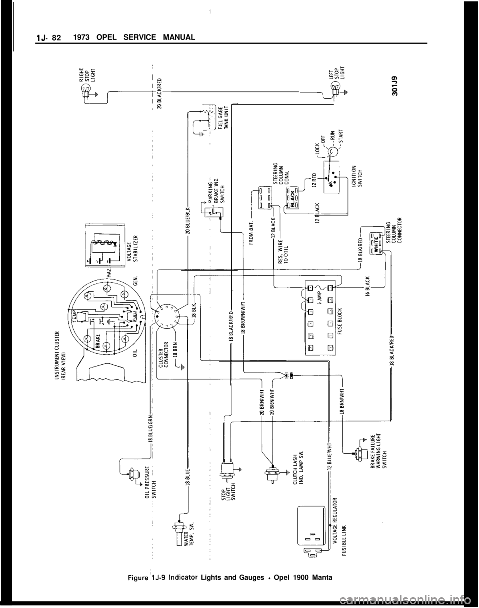
IlJ- 821973 OPEL SERVICE MANUALFigure’lJ-9 indicator Lights and Gauges
- Opel 1900 Manta
Page 247 of 625
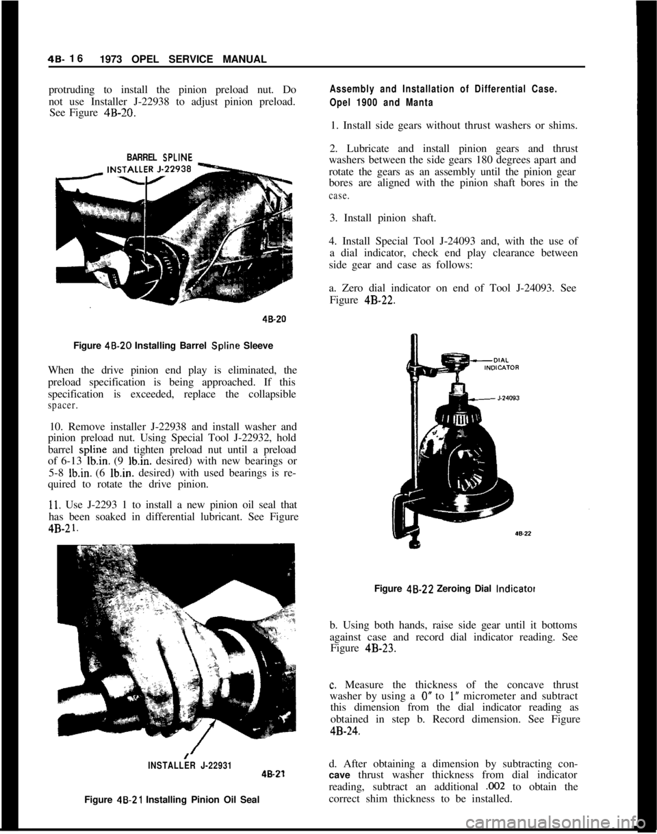
48. 16
1973 OPEL SERVICE MANUAL
protruding to install the pinion preload nut. Do
not use Installer J-22938 to adjust pinion preload.
See Figure 4B-20.
Assembly and Installation of Differential Case.
Opel 1900 and Manta1. Install side gears without thrust washers or shims.
BARREL SPLINE2. Lubricate and install pinion gears and thrust
washers between the side gears 180 degrees apart and
rotate the gears as an assembly until the pinion gear
bores are aligned with the pinion shaft bores in the
case.3. Install pinion shaft.
4. Install Special Tool J-24093 and, with the use of
a dial indicator, check end play clearance between
side gear and case as follows:
40-20a. Zero dial indicator on end of Tool J-24093. See
Figure 4B-22.
Figure 48.20 Installing Barrel Spline Sleeve
When the drive pinion end play is eliminated, the
preload specification is being approached. If this
specification is exceeded, replace the collapsible
spacer.10. Remove installer J-22938 and install washer and
pinion preload nut. Using Special Tool J-22932, hold
barrel spline and tighten preload nut until a preload
of 6-13
Ib.in. (9 Ibin. desired) with new bearings or
5-8
Ib.in. (6 lb.in. desired) with used bearings is re-
quired to rotate the drive pinion.
11. Use J-2293 1 to install a new pinion oil seal that
has been soaked in differential lubricant. See Figure4B-2
1.Figure 48.22 Zeroing Dial
lndicatotb. Using both hands, raise side gear until it bottoms
against case and record dial indicator reading. See
Figure 4B-23.
c. Measure the thickness of the concave thrust
washer by using a
0” to 1’ micrometer and subtract
this dimension from the dial indicator reading as
obtained in step b. Record dimension. See Figure
4B-24.
/INSTALLER J-22931d. After obtaining a dimension by subtracting con-48-21cave thrust washer thickness from dial indicator
reading, subtract an additional
,002 to obtain the
Figure 46.21 Installing Pinion Oil Sealcorrect shim thickness to be installed.
Page 249 of 625
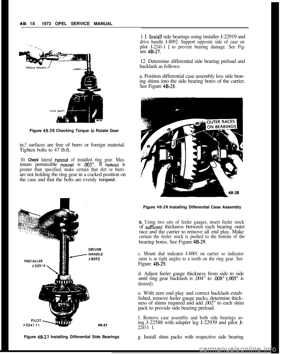
48. 181973 OPEL SERVICE MANUAL
Figure 48.26 Checking Torque
to Rotate Gear
in;! surfaces are free of burrs or foreign material.
Tighten bolts to 47 lb.ft.
10. Check lateral runout of installed ring gear. Max-imum permissible runout is
.003”. If runout is
greater than specified, make certain that dirt or burrsare not holding the ring gear in a cocked position on
the case and that the bolts are evenly
torqued.Figure 48-27 Installing Differential Side Bearings
g. Install shim packs with respective side bearing1 I.
In.stall side bearings using installer J-22919 and
drive handle J-8092. Support opposite side of case on
pilot J-2241-1
1 to prevent bearing damage. See Fig-ure
4B-27.12. Determine differential side bearing preload and
backlash as follows:
a. Position differential case assembly less side bear-
ing shims into the side bearing bores of the carrier.
See Figure
4B-28.Figure 48.28 Installing Differential Case Assembly
b. Using two sets of feeler gauges, insert feeler stockof suffcent thickness between each bearing outer
race and the carrier to remove all end play. Make
certain the feeler stock is pushed to the bottom of thebearing bores. See Figure
4B-29.
c. Mount dial indicator J-8001 on carrier so indicator
stem is at right angles to a tooth on the ring gear. SeeFigure
4B-29.d. Adjust feeler gauge thickness from side to side
until ring gear backlash is ,004” to
.OO8” (.005” is
desired).e. With zero end play and correct backlash estab-
lished, remove feeler gauge packs, determine thick-
ness of shims required and add ,002” to each shim
pack to provide side bearing preload.
f. Remove case assembly and both side bearings us-ing J-22588 with adapter leg J-22939 and pilot
J-
2241-l 1.