set OPEL GT-R 1973 Service Manual
[x] Cancel search | Manufacturer: OPEL, Model Year: 1973, Model line: GT-R, Model: OPEL GT-R 1973Pages: 625, PDF Size: 17.22 MB
Page 11 of 625
sOA- 1973 OPEL SERVICE MANUAL _
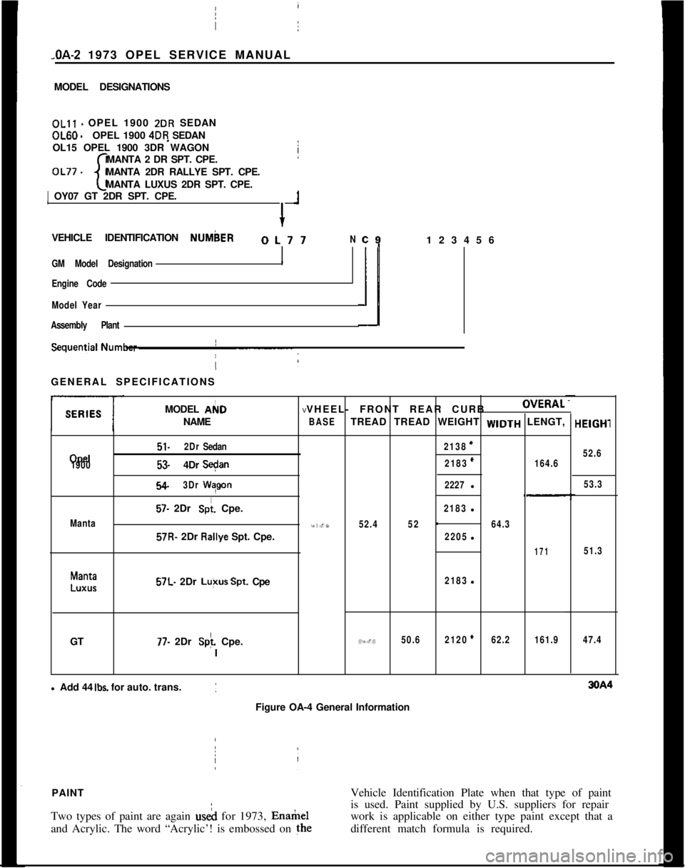
MODEL DESIGNATIONSOLll - OPEL 1900 2DR SEDANOL60
-OPEL 1900 4DR SEDAN
OL15 OPEL 1900 3DR WAGON
MANTA 2 DR SPT. CPE.
OL77 -
cMANTA 2DR RALLYE SPT. CPE.
MANTA LUXUS 2DR SPT. CPE.1 OY07 GT 2DR SPT. CPE.
+
1VEHICLE IDENTIFICATION NUMbER
OL77N
GM Model Designation
I
Engine Code
Model Year
Assembly Plant
c9123456
ilGENERAL SPECIFICATIONS
MODEL AI(ID
NAME I
Opel
1900
Manta
51.2DrSedan
53.4DrS+n
54.3DrWqgon
57. 2Dr Spi. Cpe.57R- 2Dr R&ye Spt. Cpe.
Manta
LUXUS57L. 2Dr Lu+sSpt. Cpe
GT
77. 2Dr Splf. Cpe.
IVVHEEL- FRONT REAR CURBOVERAL
BASETREAD TREAD WEIGHT WIDTH LENGT,
2138=
2183*164.6
2227l
2183l
95.752.452-64.3
2205l
171
2183l
49.450.62120*62.2161.9l Add 44
Ibs. for auto. trans.
Figure OA-4 General InformationHElGHl
52.6
53.3
51.3
47.4PAINTVehicle Identification Plate when that type of paint
Two types of paint are again useh for 1973, Enamelis used. Paint supplied by U.S. suppliers for repair
work is applicable on either type paint except that a
and Acrylic. The word “Acrylic’! is embossed on thedifferent match formula is required.
/
Page 19 of 625
CC-10 1973 OPEL SERVICE MANUAL
wiper blades. Check amount and direction of fluid
sprayed by washers during use.,
E. Defrosters - Check performance by moving con-
trols to “DEF” and noting
am$nmt of air directed
against the windshield.
I
F. Wheel Alignment and
Balabce - In addition to
abnormal tire wear, the need fbr wheel alignment
service may be indicated by a pull to the right or
!eftwhen driving on a straight and level road. The need
for wheel balancing is usually
iddicated by a vibra-
tion of the steering wheel or
se;+ tihile driving at
normal highway speeds.I
IG. Brakes
- Be alert to illumiriation of the brake
warning light or changes in braking action,
SUCK as
repeated pulling to one side, unusual sounds when
braking or increased brake pedal travel. Any of thesecould indicate the need for
brakk system inspection
and/or service.
H. Parking Brake and Transmission “PARK”
Mechanism
- Check parking brake holding ability by
parking on a fairly steep hill and restraining the vehi-
cle with the parking brake only.
eon cars with auto-
matic transmissions, check the holding ability of the
“PARK” mechanism by releasing all brakes after
the transmission selector lever hak been placed in the“P” position.
I. Glass
- Check for broken, scrritched, dirty or da-
maged glass on vehicle that
coulld obscure vision’or
become an injury hazard.
J. Lights and Buzzers
- Check all instrument panel
illuminating and warning lights,’ seat belt reminder
light and buzzer, ignition key
b&er, interior lights,
license plate lights, side marker! lights, headlamps,
parking lamps, tail lamps, brake lights, turn signals,
backup lamps, and hazard warding flashers. Have
someone observe operation of
&ach exterior light
while you activate the controls: The operation of
instrument panel warning lights is covered in the
“Starting and Operating“ section of your
Own&%
Manual.K. Transmission Shift Indicator
‘- Check to be sure
automatic transmission shift
indiCator accurately i”-
dicates the shift position selected.
I
CAUTION: Before making thk check below,I
be sure to have a clear dist&e ahead and:
behind the car, set the parking brake and
firmly apply the foot brake.
Do not depress
accelerator pedal. Be prepared to
turn off ’
ignition switch
immediat+y if engine
should start.L. Starter Safety Switch (Automatic Transmissibn
Cars)
- Check starter safety switch by placing the
transmission in each of the driving gears while
at-tempting to start the engine. The starter should oper-ate only in the Park (“P”) or Neutral (“N”)
positions.
M. Horn
- Blow the horn occasionally to be sure thatit works. (Ignition switch must be in the “ON” posi-
tion.)
N. Seat Back Latches
- Check to see that seat back
latches are holding by pulling forward on the top of
each folding seat back.
0. Rearview Mirrors and Sun Visors
- Check that
friction joints are properly adjusted so mirrors and
sun visors stay in the selected position.
P. Door Latches
- Check for positive closing, latch-
ing and locking.
Q. Hood Latches - Check to make sure hood closesfirmly by pressing on the hood at the latching point
after each closing. Check also for broken, damaged
or missing parts which might prevent secure latch-
ing.R. Fluid Leaks
- Check for fuel, water, oil or other
fluid leaks by observing the ground beneath the vehi-cle after it has been parked for a while. If gasoline
fumes or fluid are noticed at any time, the cause
should be determined and corrected without delay
because of the possibility of fire.
S. Exhaust System
- Be alert to any change in the
sound of the exhaust system or a smell of fumes
which may indicate a leak.
Head Restraints
- Check that no head restraint
components are missing, damaged or loose. (Does
not apply to GT Models).
Disc BrakesCheck brake pads and condition of rotors while
wheels are removed during tire rotation. (Note belowregarding more frequent checks also applies to disc
brakes.)
Parking and Drum BrakesCheck drum
brake linings and other internal brake
components at each wheel (drums, wheel cylinders,
etc.). Parking brake adjustment also should be
checked whenever drum brake linings are checked.
NOTE: More frequent checks should be
made if driving conditions a.nd habits result
in frequent brake application. When brakes
require relining, it is recommended thatyou use those genuine General Motors
parts specified for your car,and Delco fluid
as required.
Page 20 of 625
LUBRICATION AND MAINTENANCE OC-11
Throttle Linkage
Check for damaged or missing parts, interference or
binding. Any deficiencies should be corrected with-
out delay.
Headlights
Check for proper aim. Correct as necessary. More
frequent checks should be made if oncoming motor-
ists signal when you are already using your low
beams, or if illumination of the area ‘ahead seems
inadequate.
Underbody
In geographic areas using a heavy concentration of
road salt or other corrosive materials for snow re-
moval or road dust control, flush and inspect the
complete under side of the car at least once each
year, preferably after a winter’s exposure. Particular
attention should be given to cleaning out underbody
members where dirt and other foreign materials may
have collected.
EMISSION CONTROL MAINTENANCE
Thermostatically Controlled Air Cleaner
Inspect installation to make certain that all hoses and
ducts are connected and correctly installed. Also,
check valve for proper operation.
Carburetor Choke
Check choke mechanism for free operation. A bind-
ing condition may have developed from petroleum
gum formation on the choke shaft or from overtight-
ening of air cleaner clamp. Also check electric choke
terminal connections and fuse.
Timing, Dwell and Distributor
Adjust timing and dwell accurately as outlined under
Tune-Up in Group 6 at the first 4 months or 6,ooOmiles of operation, then at 12 month or
12,OQO mile
intervals. Adjustments must be made with test equip-
ment known to be accurate.
Replace distributor points every 12 months or 12,000
miles and carefully clean and inspect the complete
distributor cap to prevent misfiring and deteriora-
tion.
Carburetor and Idle
SpeedTorque carburetor attaching bolts and/or nuts to 12
ft.lbs. to compensate for compression of gasket atiirst 4 months or 6,000 miles of vehicle operation.Adjust idle speed to specifications with known accu-
rate equipment.
Proper functioning of the carburetor is particularly
essential to control of emissions. Correct mixtures
for emission compliance and idle quality have been
preset by Opel. Plastic idle mixture limiters have
been installed on the idle mixture screw, idle air
screw, and throttle stop screw to preclude unauthor-
ized adjustment. The plastic caps on the idle mixture
screw and the idle adjustment screw must be
removed to perform an idle speed adjustment. The
plastic cap on the throttle stop screw is not to be
removed unless some major carburetor repair or re-
placement which affects the throttle stop screw ad-
justment has been necessary.
Carburetor Fuel Inlet Filter
Replace filter at 12 month or
12,OCO mile intervals
or more often if clogged.
Spark Plugs
Replace at
6,ooO mile intervals when operating with
leaded fuels or at 12,000 mile intervals when using
unleaded fuels. Use of leaded fuels results in lead
deposits on spark plugs and can cause misfiring at
mileages less than
12,OilO miles. Where misfiring oc-
curs prior to
6,ooO miles, spark plugs in good condi-
tion can often be cleaned, tested and reinstalled in an
engine with acceptable results.
Spark Plug Wires
Inspect spark plug wires for evidence of checking or
cracking of exterior insulation and tight fit in the
distributor cap and at the spark plugs. Exterior of
wires should be cleaned, any evidence of corrosion
on ends removed and wire replace if deteriorated.
Positive Crankcase Ventilation System
The PCV metered orifice should be cleaned at 12,000
mile intervals under normal use, and at 6,000 mile
intervals when the vehicle is used under the follow-
ing conditions: driving in dusty conditions, extensive
idling, trailer pulling and short trip operation at
freezing temperatures (engine not thoroughly
warmed-up).
Evaporation Control System
Check all fuel and vapor lines and hoses for proper
connections and correct routing as well as condition.
Remove canister and check for cracks or damage.
Replace damaged or deteriorated parts as necessary.
Replace filter in open end of canister at 24month/24,000 mile intervals.
Page 24 of 625
BATTERY AND CABLES - ALL MODELSlA- 3
lost as the result of charging and discharging, and it
must be replaced before the electrolyte level falls to
the tops:of the separators. If the water is not replacedand the plates become exposed, they may become
permanently sulphated, which would impair the
per-forma”& of the plates. Also, the plates cannot take
full
par! in the battery action unless they are com-
pletely covered by the electrolyte.
Importance of Keeping Battery Properly Charged
The battery has three major functions: (1) It provides
a source of energy for cranking the engine. (2) It actsas a stabilizer to the voltage in the electrical system.
(3) It
c+n for a limited time furnish energy when the
demand: of the electrical units in operation exceed
the output of the generator.
In
ordei for the battery to continue to function, it is
necessaiy that current withdrawal from the battery
be balanced by current input from the generator so
that the battery is maintained in a properly chargedconditidn. If the outgo exceeds the input, the battery
will be&me discharged so that it cannot.supply suffi-cient energy.
The state of charge of the battery as well as the
temperature of the electrolyte has an important bear-ing on its capacity for supplying energy. Battery effi-
ciency is greatly reduced by decreased electrolyte
temper&e as it has a decided numbing effect on its
electrodhemical action. Under high discharge such
as cranking, battery voltage drops to lower values incold temperatures than in warm temperatures.
In
extrkmely cold climates it is important to keepbatter& in a nearly full charged condition to avoid
the possibility of freezing, which will damage any
battery!
The following table shows the temperatures at whichfreezing will occur in electrolytes of
differennt densi-
ties, wifh specific gravity corrected to 80 degrees l?
Specific Gravity Freezing Point
1.220 -35 degrees F.
1.200
-35 degrees F.
1.160
d degrees F.
Care of Dry Batteries in StorageA “dry charge” battery contains fully charged posi-
tive
a$ negative plates but no electrolyte.
Dry charged batteries should be stored in a dry placeaway from excessive heat. A dry charged battery
should
p kept in its original carton until ready to beput into service. This type of battery will retain its
“charged” condition indefinitely if protected from
moisture. Dry batteries may be stacked in vertical
columns provided they are not stacked more than
four high.
Preparing Dry Charged Batteries For ServiceTo prepare “dry charge” batteries for service use
approved battery-grade acid electrolyte (1.265 sp. gr.
at 80 degrees F). Care should be exercised in its useto prevent bodily injury or damage to clothing or
other material resulting from actual contact with the
electrolyte.
Electrolyte should be added to dry charged batteriesin an area where water is readily available for flush-
ing in case the electrolyte comes into contact with the
body. Refer to instructions on side of electrolyte con-tainer for antidotes to use if electrolyte comes into
contact with the body.
It is strongly recommended that a person filling bat-
teries with electrolyte wear glasses (preferably safetyglasses) to prevent possible damage to the eyes
should any spattering of the electrolyte occur.
1, Remove dry charged battery from its original car-
ton.2. Remove the vent plugs.
3. Using a glass or acid-proof plastic funnel, till eachbattery cell with electrolyte. Do not use a metal
funnel for filling the battery. The cell is properlytilled when the electrolyte level rises to the split ring
at the bottom of the vent well. Do not overfill orundertill. Overfilling will cause acid corrosion in the
,battery area; undertilling will cause early battery fail-
UR.4. After tilling cells, wait five to ten minutes and add
additional electrolyte, if necessary, to bring the elec-
trolyte to the proper level.
5. Never finish tilling a dry charge battery with wa-
ter. If electrolyte is spilled, more electrolyte must be
obtained.
Test After Batteries
ere Prepared For ServiceThe Delco Dry Charge Battery may be put into ser-
vice immediately after activation. However, to insuregood battery performance, the following activation
tests are recommended:1. After adding electrolyte,, check the open circuit
voltage. Less than 10 volts mdicates a reverse cell oran open circuit and the battery should be replaced.
2. Check the specific gravity of all cells. If the specific
Page 26 of 625
BATTERY AND CABLES - ALL MODELSlA- 5
and terminal connections should not exceed 2/10
volt.
5. Connedt voltmeter positive lead to ground on en-
gine.
At&h prod to voltmeter negative lead and
apply prod to center of battery negative post. Volt-
age drop across the battery ground cable and termi-
nal conne$tions should not exceed 2/10 volt at
200amps.
6. A reading in excess of 2/10 volt when testing
either battery cable indicates excessive resistance in
cable or cpnnections. Clean and tighten cable or con-
nections. Clean and tighten cable terminals
(sub-para. c, below) and recheck for voltage drop. If volt-
age drop Still exceeds 2/10 volt, replace cable with a
genuine Buick-Opel cable to insure ample capacity.
Undercharge Failure of BatteryThe most frequent trouble experienced with storage
batteries is failure to maintain a state of charge suffi-
cient to crank the engine and also furnish current to
the ignitibn system, lights and accessories. Failure to
maintain a proper state of charge may be due to one
or more of the following conditions:
1.
Opertiting Conditions. When determining cause
of premature failure of a battery, consideration must
be given /to the conditions under which the car is
operated.,
In very low temperatures the capacity of a storage
battery
ii considerably reduced and the energy re-
quired f& cranking the. engine is considerably in-
creased. :
Frequent starting, particularly in cold weather,
ac-compani
place in the limited running time. This condition is
aggravated by night driving when lights are turned
on, or by operation of an air conditioner in heavy
traffic.
When thk car is operated under these conditions,adjusting,the voltage regulator to the high limit may
allow enough increase to keep the battery at a safe
state of charge. If the high limit setting does not
maintain a safe state of charge, an occasional booster
charge should be given to the battery.
2. Low charging Rate. In case of premature battery
failure, tbe charging rate of alternator should always
be checked and adjusted if below specifications.
3.
Zntemd Condition The internal condition of the
battery niay be such that it cannot hold a chargesatisfactoiily. Check electrolyte level and test the
battery using the 421 Battery Test.
Overcharge Failure of BatteryA common cause of battery failure is overcharging,
that is, continued input of excessive charging current
after the battery has reached a fully charged condi-
tion.
One evidence that battery is being overcharged is the
need for frequent addition of water to the battery in
order to maintain the electrolyte level above the tops
of the battery separators, since overcharging causes
rapid water loss. When this becomes evident, the
charging rate of alternator should be immediately
checked, as well as the voltage regulator, and ad-
justed to avoid internal damage to battery.
ADJUSTMENTS AND MINOR SERVICEPERIODIC BATTERY INSPECTION AND SERVICE
The battery requires very little attention, but peri-
odic inspection is essential to secure the maximum
efficiency and life. The following services are essen-
tial to maintain the battery at maximum efficiency.
WARNING: Never expose battery to open flame or
electric spark
- battery action generates hydrogen gas
which is flammable and explosive. Do not allow bat-
tery fluid to contact skin, eyes, fabrics or painted
surfaces
- fluidis a sulfuric acid solution which could
cause serious personal injury or property damage.
Wear eye protection when working with battery.
Maintain Electrolyte LevelAdd distilled water as required to maintain the elec-
trolyte level at the split ring at bottom of tiller well.
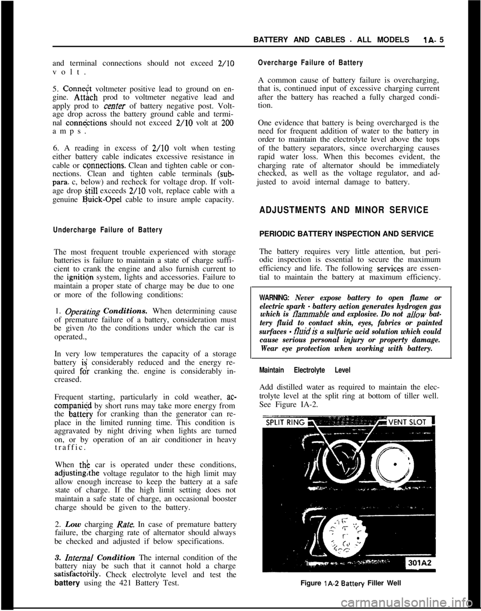
See Figure IA-2.
Figure lA-2
Battery Filler Well
Page 27 of 625
j
/lA- 61973 OPEL SERVICE MANUAL
Do not overfill, as electrolyte may
be sprayed out by
gassing or may overtlow due to heat expansion dur:
ing charging.
If distilled water is not available, it is better to add
clean, mineral-free tap water than to allow the
elec2trolyte level to remain below the top of the plates:
In freezing weather the water should be added just
before using the car or otherwise charging the bat-
tery so that the water will be mixed with the acid
before it is allowed to stand in freezing temperatures.
If it is found necessary to add water to the
batterimore frequently than about every
1,ooO miles and the
quantity of water added per cell is’ excessive, check
setting of voltage regulator and adjust, if necessary:
Abnormal water loss is an indication that the battery
is being overcharged.
Inspect Battery, Mounting and Cables
Check outside of battery for damage or signs of se&ous abuse such as broken case or broken covers:
Check inside of battery by removing the vent caps
and inspecting for signs of abuse
stich as electrolyte
level too low to see, or bad or unusual odors. If
battery shows signs of serious damage or abuse, it
should be replaced.
Check the battery hold down bolts to make certain
that battery is securely held in place. The nut should
be drawn up to 20 lbs. in.;excessjve tightening may
distort or crack the battery case.If the top of battery is dirty or the hold down str?e
is corroded, clean thoroughly with a brush dipped
IFammonia or soda solution. Care must be used td
prevent any solution from getting into battery
cellslAfter the foaming of solution stops, flush off witli
clean water and dry thoroughly. If hold down strap
is corroded it should be painted with acid-resisting
paint after cleaning.
Check battery cables to make certain they are tight
at bracket and junction block. If a connection is
found loose it should be cleaned before being tight;ened as arcing and corrosion may have taken place
in the loose connection. Check condition of cables
and replace if badly corroded or frayed.
Special attention must be given to,the battery posi-
tive cable position to eliminate the possibility of con-
tact with the exhaust manifold on the 1.1 liter engine.
The cable clamp must be rotated clockwise as neces-
sary for the cable to run at a 45 degree angle toward
the right wheelhouse panel.
Cleaning Cable Terminals
If loose connections are found by inspection, or highresistance is found by voltage test, disconnect the
cable for thorough cleaning of terminals. When
removing a corroded cable terminal from battery
post, do not pry against battery case or hammer on
terminal to break it loose, since either practice will
result in broken cell covers. Use a screw-type termi-
nal puller if terminal cannot be loosened by hand.
Thoroughly clean all corrosion from disconnected
battery cable terminals and terminal posts, using
suitable wire brushes. If wire brushes are not availa-
ble, corroded terminals may be cleaned by brushing
with a strong soda solution, using care not to get
solution into battery cells.
If
cabbz strands are broken, corroded, or loose in
terminals, the cable should be replaced with the cor-
rect cable to insure ample capacity.
To prevent corrosion of battery terminals and con-
nections, apply a coating of petroleum jelly over the
battery post and cable terminals after cables have
been installed on terminals.
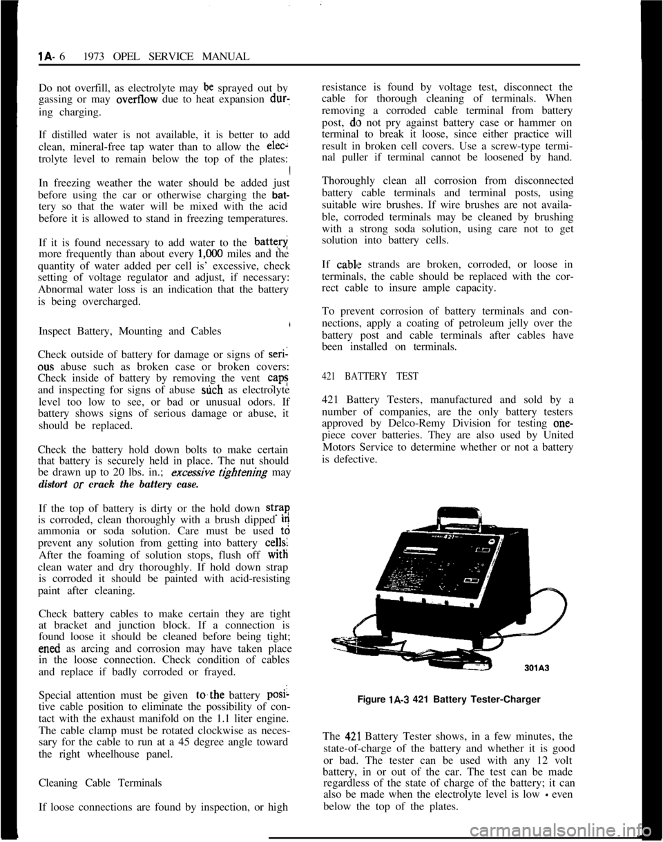
421 BATTERY TEST421 Battery Testers, manufactured and sold by a
number of companies, are the only battery testers
approved by Delco-Remy Division for testing one-
piece cover batteries. They are also used by United
Motors Service to determine whether or not a battery
is defective.
Figure lA-3 421 Battery Tester-Charger
The
42,l Battery Tester shows, in a few minutes, the
state-of-charge of the battery and whether it is good
or bad. The tester can be used with any 12 volt
battery, in or out of the car. The test can be made
regardless of the state of charge of the battery; it can
also be made when the electrolyte level is low
- even
below the top of the plates.
Page 28 of 625
BATTERY AND CABLES - ALL MODELSlA- 7
421 Test
F$ocedure1. Visual Inspection
- The first step in testing the
Energizer br 12-V& Battery should be a visual in-
spection
which very often will save time, labor and
expense in determining the condition.
(a) Check for broken or cracked case or cover.
(b) Check ,for loose terminal posts.
fiozeck Ifor defective or mutilated sealing com-(d) Check for other visible signs of physical damage.
Obvious d?mage as a result of conditions described
above indicates the need for Energizer or batteryreplaceme$t.
2. The “421” Test is a programmed test procedure
consisting bf a series of timed discharge and charge
events, reqtdring approximately 2 to 3 minutes, that
will determine the condition of the Energizer or bat-
tery with a high degree of accuracy when used inconjunctioti with this entire test procedure. “421”
Testers
a$ produced by a number of different manu-
facturers
r+nd their directions for tester operation
should be carefully followed. General comments on
overall “42 1” Tester operation follow:
(a) Energi@rs or batteries should
nor be charged
prior to
making this test. Defects within the unit can
be hidden by the charging and erroneous test results
will be obtpined.
(b) Erratic, or extremely low, initial meter readings
may indicate poor connections at the tester termi-
nals.Obt{in clean and tight connections beforeper-
forming the 421
Test.(c) All meter readings should be made immediately
after the meter indicator light comes on even if the
meter needle is still moving.
(d) If additional discharges are required after the
initial discbarge, set meter indicator following thefast discharge cycle.
(e) Batteries designated as “bad” by the tester should
be replaced.
(f) Batteries designated as “good” with no owner’s
complaint or indication of poor performance, should
be left in s+vice. Posts, cable clamps, and top should
be cleaned, water should be added and recharging
should be
,performed, if required. For dependable
and reliable battery service, the battery should be in
at least a
75 per cent state-of-charge.
(g) Batteries designated as “good” that are suspected
of being questionable because of owner complaint, orage of the battery, should be further tested by the
Hydrometer Test.
HYDROMETER TEST OF BATTERY
The 421 Battery Test as described in the previous
paragraph is the fastest and most accurate means of
determining the serviceability of a one-piece cover
battery. However, ifa 421 Battery Tester is not avail-
able, a hydrometer test may be used on a battery that
has failed to give proper service.
Hydrometer Test1. Fully charge battery.
2. Measure specific gravity of each cell as described
in sub-paragraph below.
Decide battery serviceability as follows:
(a) If all cells read between 1.230 and 1.310, the
battery is okay. All it needed was a full charge.
(b) After fully charging battery, if any cell reads less
than 1.230, the battery is defective and should be
replaced.
Use of HydrometerThe Hydrometer measures the percentage of sulphu-
ric acid in the battery electrolyte in terms of specific
gravity. As a battery drops from a charged to a dis-
charged condition, the acid leaves the solution and
enters the plates, causing a decrease in specific
gravity of electrolyte. With a hydrometer, an indica-
tion of the concentration of the electrolyte is ob-
tained.
The specific gravity of the electrolyte varies not only
with the percentage of acid in the liquid, it also varies
with temperature. As temperature increases, the
electrolyte expands so that the specific gravity is re-
duced. As temperature drops, the electrolyte con-
tracts so that the specific gravity increases. Unless
these variations in specific gravity are taken into
account, the specific gravity obtained by the hy-
drometer may not give a true indication of the con-
centration of acid in the electrolyte.
Correction can be made for temperature by adding
,004, usually referred to as 4 “points of gravity”, to
the hydrometer reading for every 10 degrees F. that
the electrolyte is above 80 degrees F. or subtracting004 for every 10 degrees F. that electrolyte is below
80 degrees F. Figure IA-4 shows the exact correctionfigure to use for any temperature above or below 80
degrees F., the three steps used in obtaining the cor-
rected or true specific gravity, and two examples
showing how it is figured.
Page 40 of 625
IIIGNITION SYSTEMlC- 19
11. (Startx position.) The ignition key must be
released as soon as engine starts. The switch then
returns aujomatically to the on position.
IGNITION
GOILThe ignition coil consists of a laminated non- mag-
netic iron
(core enclosed by two coils; the primary
winding and the secondary winding.
The prim+y circuit consists of the power source
(battery), the ignition switch, the ignition coil pri-
mary winding, the distributor breaker points with
ignition condenser connected in parallel, and all con-
necting
lo& tension wiring.
The secondary circuit consists of the ignition coil
secondary ‘winding, the spark plugs, all connecting
high tens@ wiring, the distributor cap and the
ro-tor.
When the’ ignition switch is turned on and the
breaker pdints are closed, current flows through the
ignition
c&l primary winding and produces a mag-
netic field wound the coil windings.
When the breaker points are separated by the revolv-
ing distributor cam, the magnetic field collapses and
induces a high voltage surge in the secondary wind-
ing,
produ;cing a spark between the spark plug elec-
trodes. ,
The ignitidn condenser which is connected in paral-
lel with the breaker points, prevents arcing between
the
separa’ted breaker contacts, and current flow
after~ the breaker points have been separated, thus
causing a kery rapid collapse of the magnetic field
around th$ Ignition coil.
/
IGNITION ‘DISTRIBUTORThe ignitidn distributor breaks the primary current,distributeslthe high voltage surges induced in the coil
secondary winding to the spark plugs according to
the engin< tiring order and sets ignition timing in
relation to. engine RPM and load.
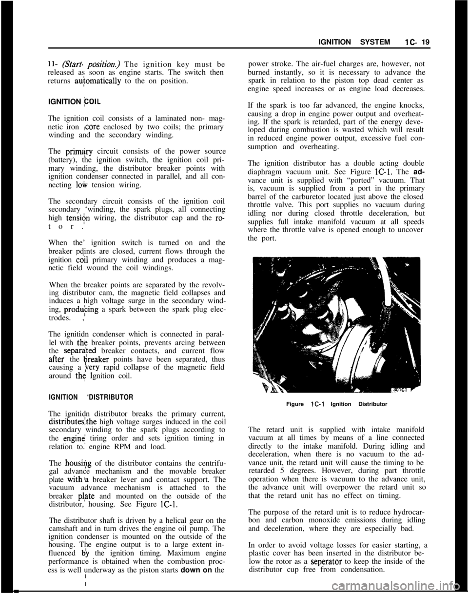
The housi+g of the distributor contains the centrifu-
gal advance mechanism and the movable breaker
plate with’s breaker lever and contact support. The
vacuum advance mechanism is attached to the
breaker plate and mounted on the outside of the
distributor, housing. See Figure lC-1.
The distributor shaft is driven by a helical gear on the
camshaft and in turn drives the engine oil pump. The
ignition condenser is mounted on the outside of the
housing. The engine output is to a large extent in-
fluenced b) the ignition timing. Maximum engine
performance is obtained when the combustion proc-
ess is well underway as the piston starts down on thepower stroke. The air-fuel charges are, however, not
burned instantly, so it is necessary to advance the
spark in relation to the piston top dead center as
engine speed increases or as engine load decreases.
If the spark is too far advanced, the engine knocks,
causing a drop in engine power output and overheat-
ing. If the spark is retarded, part of the energy deve-
loped during combustion is wasted which will result
in reduced engine power output, excessive fuel con-
sumption and overheating.
The ignition distributor has a double acting double
diaphragm vacuum unit. See Figure lC-1. The ad-
vance unit is supplied with “ported” vacuum. That
is, vacuum is supplied from a port in the primary
barrel of the carburetor located just above the closed
throttle valve. This port supplies no vacuum during
idling nor during closed throttle deceleration, but
supplies full intake manifold vacuum at all speeds
where the throttle valve is opened enough to uncover
the port.
Figure lC-1 Ignition Distributor
The retard unit is supplied with intake manifold
vacuum at all times by means of a line connected
directly to the intake manifold. During idling and
deceleration, when there is no vacuum to the ad-
vance unit, the retard unit will cause the timing to be
retarded 5 degrees. However, during part throttle
operation when there is vacuum to the advance unit,
the advance unit will overpower the retard unit so
that the retard unit has no effect on timing.
The purpose of the retard unit is to reduce hydrocar-
bon and carbon monoxide emissions during idling
and deceleration, where they are especially bad.
In order to avoid voltage losses for easier starting, a
plastic cover has been inserted in the distributor be-
low the rotor as a seperator to keep the inside of the
distributor cup free from condensation.
Page 41 of 625
I
ilC- 201973 OPEL SERVICE MANUAL
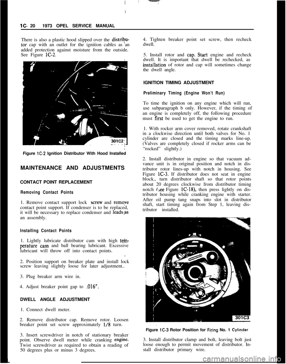
There is also a plastic hood slipped over the distrivu-tar cap with an outlet for the ignition cables as an
added protection against moisture from the outside.
See Figure lC-2.
Figure lC-2 Ignition Distributor With Hood Installed
MAINTENANCE AND ADJUSTMENTS
CONTACT POINT REPLACEMENT
Removing Contact Points1. Remove contact support lock
,screw and remqve
contact point support. If condenser is to be replaced,
it will be necessary to replace condenser and
1eads;asan assembly.
Installing Contact Points1. Lightly lubricate distributor cam with high tein-perature cam and ball bearing lubricant. Excessive
lubricant will throw off into contact points.
:
,
2. Position support on breaker plate and install lock
screw leaving slightly loose for later adjustment..
3. Plug breaker arm wire in.
4. Adjust breaker point gap to ,016”.
/
DWELL ANGLE ADJUSTMENT
1. Connect dwell meter.
2. Remove distributor cap. Remove rotor. Loosen
breaker point set screw approximately
l/8 turn.
3. Insert screwdriver in notch of stationary breaker
point. Observe dwell meter while cranking engine.
Twist screwdriver as required to obtain a reading of
50 degrees plus or minus 3 degrees.4. Tighten breaker point set screw, then recheck
dwell.
5. Install rotor and cap.~Start engine and recheck
dwell. It is important that dwell be rechecked, as
instal~lation of rotor and cap will sometimes change
the dwell angle.
IGNITION TIMING ADJUSTMENT
Preliminary Timing (Engine Won’t Run)To time the ignition on any engine which will run,
use subparagraph b only. However, if the timing of
an engine is completely off, the following procedure
must first be used to get the engine to run.
1. With rocker arm cover removed, rotate crankshaft
in a clockwise direction until both valves for No. 1
cylinder are closed and the timing marks line-up.
(Valves are completely closed if rocker arms can be
“rocked” slightly.)
2. Install distributor in engine so that vacuum ad-
vance unit is in original position and notch in dis-
tributor rotor lines-up with notch in housing. See
Figure lC-3. If distributor does not seat in engine
block., turn distributor shaft so that rotor points
about 20 degrees clockwise from distributor timing
notch
(see Figure lC-18), then press lightly on dis-
tributor housing while cranking engine with starter.
After oil pump tang snaps into slot in distributor
shaft, start timing again from Step 1, leaving dis-
tributor installed.
Figure lC-3 Rotor Position for Filing No. 1 Cyliqder
3. Install distributor clamp and bolt, leaving bolt just
loose enough to permit movement of distributor. In-
stall distributor primary wire.L
Page 42 of 625
IGNITION SYSTEMlC-214. Rota&distributor counterclockwise slightly until
contact pbints just start to open. This must be done
very carefully or engine will not start.
5. Install distributor cap. Make sure spark plug wires
are correctly installed in distributor cap, through clip
and on spark plugs.
Finish TimingIContact boint gap
(.016” at widest gap) or dwell 50
degrees plus or minus 3 degrees should always be
checked before adjusting ignition timing.
1. Connekt timing light to No. 1 spark plug.
2. Disconnect and plug vacuum advance unit and
retard u$it hoses.
3. Connect a tachometer from distributor side of coil
to
groun$l.4. Start dngine. Set idle speed to 900 RPM.
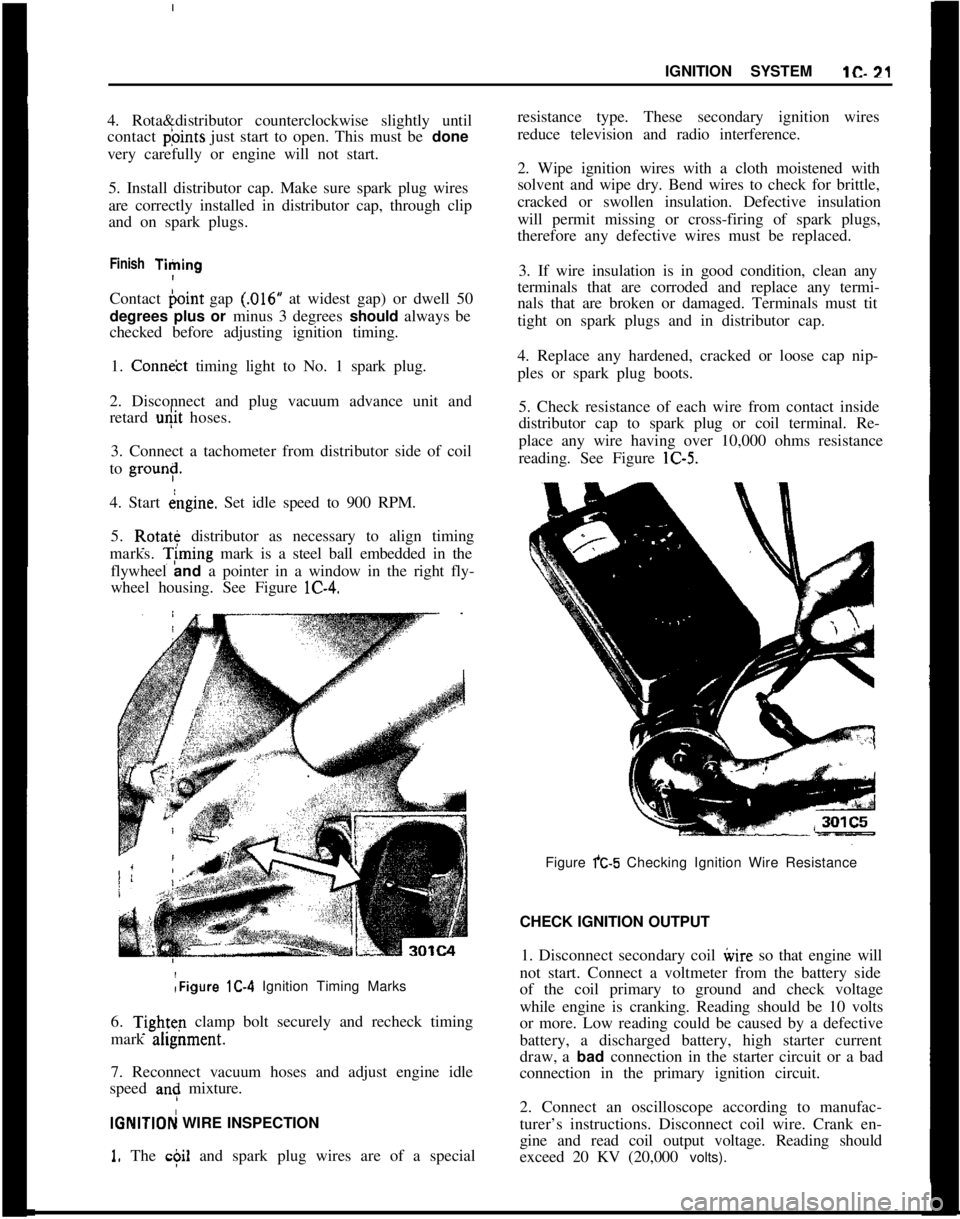
5. Rotate distributor as necessary to align timing
marks. T;ming mark is a steel ball embedded in the
flywheel and a pointer in a window in the right fly-
wheel housing. See Figure lC-4.:Figure lC-4 Ignition Timing Marks
6.
Tightq clamp bolt securely and recheck timing
mark ahgnment.
7. Reconnect vacuum hoses and adjust engine idle
speed
an: mixture.
IGNlTlOFj WIRE INSPECTION
1. The c$il and spark plug wires are of a specialresistance type. These secondary ignition wires
reduce television and radio interference.
2. Wipe ignition wires with a cloth moistened with
solvent and wipe dry. Bend wires to check for brittle,
cracked or swollen insulation. Defective insulation
will permit missing or cross-firing of spark plugs,
therefore any defective wires must be replaced.
3. If wire insulation is in good condition, clean any
terminals that are corroded and replace any termi-
nals that are broken or damaged. Terminals must tit
tight on spark plugs and in distributor cap.
4. Replace any hardened, cracked or loose cap nip-
ples or spark plug boots.
5. Check resistance of each wire from contact inside
distributor cap to spark plug or coil terminal. Re-
place any wire having over 10,000 ohms resistance
reading. See Figure lC-5.
Figure fC-5 Checking Ignition Wire Resistance
CHECK IGNITION OUTPUT
1. Disconnect secondary coil ivire so that engine will
not start. Connect a voltmeter from the battery side
of the coil primary to ground and check voltage
while engine is cranking. Reading should be 10 volts
or more. Low reading could be caused by a defective
battery, a discharged battery, high starter current
draw, a bad connection in the starter circuit or a bad
connection in the primary ignition circuit.
2. Connect an oscilloscope according to manufac-
turer’s instructions. Disconnect coil wire. Crank en-
gine and read coil output voltage. Reading should
exceed 20 KV (20,000 volts).