stop start OPEL GT-R 1973 Service Manual
[x] Cancel search | Manufacturer: OPEL, Model Year: 1973, Model line: GT-R, Model: OPEL GT-R 1973Pages: 625, PDF Size: 17.22 MB
Page 16 of 625
LUBRICATION AND MAINTENANCE OC-7SERVICESLUBE AND GENERAL MAINTENANCE
Vehicle operation under conditions such as heavy
dust, continuous short trips, use of other than un-
leaded or low lead fuels or pulling trailers, is not
considered normal use and therefore more frequent
maintenance will be required. Such additional
maintenance requirements are included where appli-
cable.
Engine OilChange each 4 months or
3,COO miles, whichever
occurs first, or each 2 months or
3,ooO miles when
the vehicle is operated under the following condi-
tions: (a) driving in dusty conditions, (b) trailer pull-
ing, (c) extensive idling or (d) short-trip operation at
freezing temperatures (with engine not thoroughly
warmed-up).Engine oils have a definite effect on ease of starting,
oil economy, combustion chamber deposits and en-
gine wear. It is recommended that a” oil which,
according to the label on the can is; (1) intended for
service SE and (2) passes car makers’ tests be used.
Oils confotming to these types contain detergent ad-
ditives. -
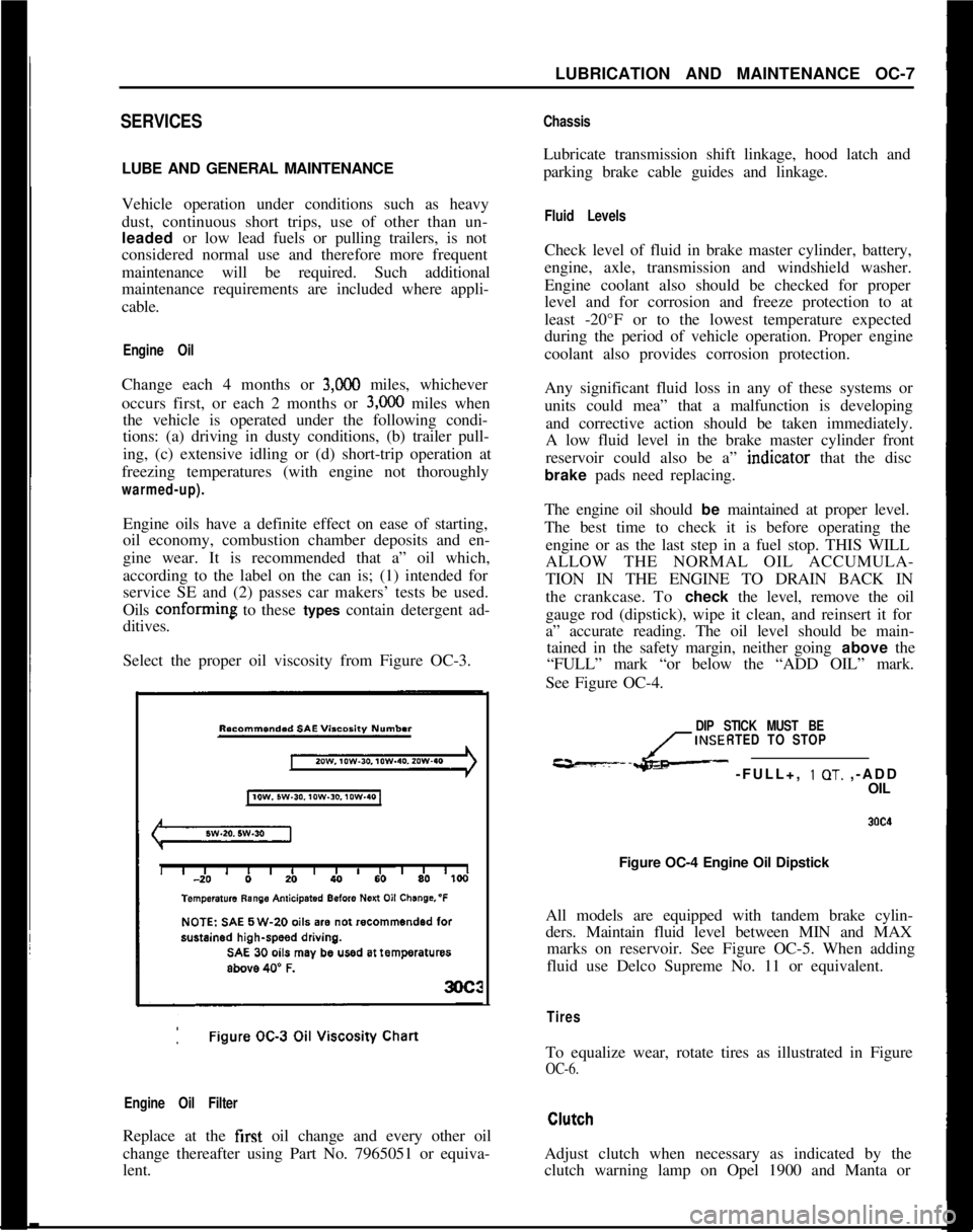
Select the proper oil viscosity from Figure OC-3.
Engine Oil FilterReplace at the first oil change and every other oil
change thereafter using Part No. 7965051 or equiva-
lent.
ChassisLubricate transmission shift linkage, hood latch and
parking brake cable guides and linkage.
Fluid LevelsCheck level of fluid in brake master cylinder, battery,
engine, axle, transmission and windshield washer.
Engine coolant also should be checked for proper
level and for corrosion and freeze protection to at
least -20°F or to the lowest temperature expected
during the period of vehicle operation. Proper engine
coolant also provides corrosion protection.
Any significant fluid loss in any of these systems or
units could mea” that a malfunction is developing
and corrective action should be taken immediately.
A low fluid level in the brake master cylinder front
reservoir could also be a” indtcator that the disc
brake pads need replacing.
The engine oil should be maintained at proper level.
The best time to check it is before operating the
engine or as the last step in a fuel stop. THIS WILL
ALLOW THE NORMAL OIL ACCUMULA-
TION IN THE ENGINE TO DRAIN BACK IN
the crankcase. To check the level, remove the oil
gauge rod (dipstick), wipe it clean, and reinsert it for
a” accurate reading. The oil level should be main-
tained in the safety margin, neither going above the
“FULL” mark “or below the “ADD OIL” mark.
See Figure OC-4.
DIP STICK MUST BE
INSERTED TO STOP
---L- -FULL+, 1 OT. ,-ADD
OIL
Figure OC-4 Engine Oil Dipstick
All models are equipped with tandem brake cylin-
ders. Maintain fluid level between MIN and MAX
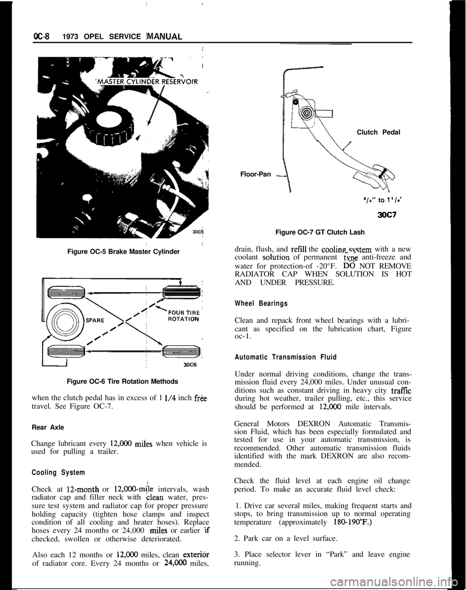
marks on reservoir. See Figure OC-5. When adding
fluid use Delco Supreme No. 11 or equivalent.
TiresTo equalize wear, rotate tires as illustrated in Figure
OC-6.Adjust clutch when necessary as indicated by the
clutch warning lamp on Opel 1900 and Manta or
Page 17 of 625
IoC-91973 OPEL SERVICE MANUAL
Figure OC-5 Brake Master Cylinder
I
Figure OC-6 Tire Rotation Methods
when the clutch pedal has in excess of 1
l/4 inch fr&
travel. See Figure OC-7.
Rear Axle
Change lubricant every
12,ooO miies when vehicle is
used for pulling a trailer.
Cooling SystemCheck at 12-month or
12,000~mile intervals, wash
radiator cap and filler neck with clean water, pres-
sure test system and radiator cap for proper pressure
holding capacity (tighten hose clamps and inspect
condition of all cooling and heater hoses). Replace
hoses every 24 months or 24,000 ,miles or earlier :if
checked, swollen or otherwise deteriorated.
Also each 12 months or
12,ooO miles, clean exteribr
of radiator core. Every 24 months or
24,OCO miles,Floor-Pan
-Clutch Pedal
Figure OC-7 GT Clutch Lash
drain, flush, and refill the cooline svstem with a new
coolant so&ion of permanent
6~; anti-freeze and
water for protection-of -20°F.
D-6 NOT REMOVE
RADIATOR CAP WHEN SOLUTION IS HOT
AND UNDER PRESSURE.
Wheel BearingsClean and repack front wheel bearings with a lubri-
cant as specified on the lubrication chart, Figure
oc-1.
Automatic Transmission FluidUnder normal driving conditions, change the trans-
mission fluid every 24,000 miles. Under unusual con-
ditions such as constant driving in heavy city traffic
during hot weather, trailer pulling, etc., this service
should be performed at
12,COO mile intervals.
General Motors DEXRON Automatic Transmis-
sion Fluid, which has been especially formulated and
tested for use in your automatic transmission, is
recommended. Other automatic transmission fluids
identified with the mark DEXRON are also recom-
mended.
Check the fluid level at each engine oil change
period. To make an accurate fluid level check:
1. Drive car several miles, making frequent starts and
stops, to bring transmission up to normal operating
temperature (approximately
180-190’F.)2. Park car on a level surface.
3. Place selector lever in “Park” and leave engine
running.
Page 33 of 625
19- 12 1973 OPEL SERVICE MANUAL :ConditionPosiible CauseCorrection4. Voltage drop.1. Check wiring and wiring
connections.
5. Overrun&g clutch slips.1. Replace overrunning clutch.
The cranking motor keeps
on rotating after ignition
switch is off.1. Ignition
{witch does not
cut off or solenoid switch
sticks.
1, Immediately disconnect cranking
motor cable from battery. Inspect
and/or replace or repair ignition and
solenoid switches as required.
The drive pinion does notdemesh after engine has
been cranked.1. Drive pinion or ring gear
1. Clean components as specified.
teeth clogged or flattened.Replace as required.
Return spring slack or broken.MAlNTEilANCE AND ADJUSTMENT
/
STARTING SYSTEM CHECKS
Voltage Loss ChecksWhen the starter cranks too slowly, check the bat-
tery state of charge and all electrical connections
between the battery and starter.
1. Turn on headlights and
opera’te starter. If head-
lights dim considerably when starter is engaged, the
battery may be discharged or be defective. Check the
battery.
2. If the headlights stay bright but the starter d&s
not turn over, the starter cables may be faulty or the
starter defective.
(a) Test battery voltage while cranking engine
1(9volts minimum).
(b) Check voltage from starter tkrminal of solenoid
to starter frame while cranking engine.
3. The difference in readings taken in Operations 2a
and 2b above represents the
volt& drop through the
cables and solenoid switch. Voltdge drop should
Gotexceed
.5 volt.
4. Locate excessive resistance as follows:
(a) Turn voltmeter to scale above 12 volts and con-
nect voltmeter leads
across connection or switch: to
be checked.
(b) With starter switch closed, turn voltmeter switch
to lowest scale and take reading as quickly as possi-
ble, then turn switch back to higher scale and stop
cranking engine.(c) Voltmeter must not read more than
.2 volt across
any
c:onnection. If voltmeter reads more than .2 volt,
the
d~efect must be corrected.
Starter Current Draw - Lock Test1. Make sure battery is fully charged and in good
condition.
2. Connect a volt ampere starter tester according to
manufacturer’s instructions.
3. Pull parking brake on securely, shift transmission
into 4th (direct) gear and actuate starter. (Starter will
not
t,urn engine because engine is locked through
transmission.)
4. While starter is actuated, read voltage and current.
Refer to Specification Chart.
(a) Voltage low
_ poor battery or a voltage loss in the
starter circuit.
(b) Current high
- short circuit in starter. Overhaul
starter.
(c) Current low
- commutator dirty, brushes worn,
solenoid switch contacts defective or open circuit in
starter. Overhaul starter.
Starter Current Draw. On Car1. Bring engine to normal operating temperature.
2. Stop engine and disconnect coil wire from dis-
tributor.
3. Ground coil wire to prevent excessive coil voltage
build up.
Page 37 of 625
lB- 16 1973 OPEL SERVICE MANUAL
8. Making sure that brush holder is aligned at right
angles to the
field frame, rivet brush holder to field
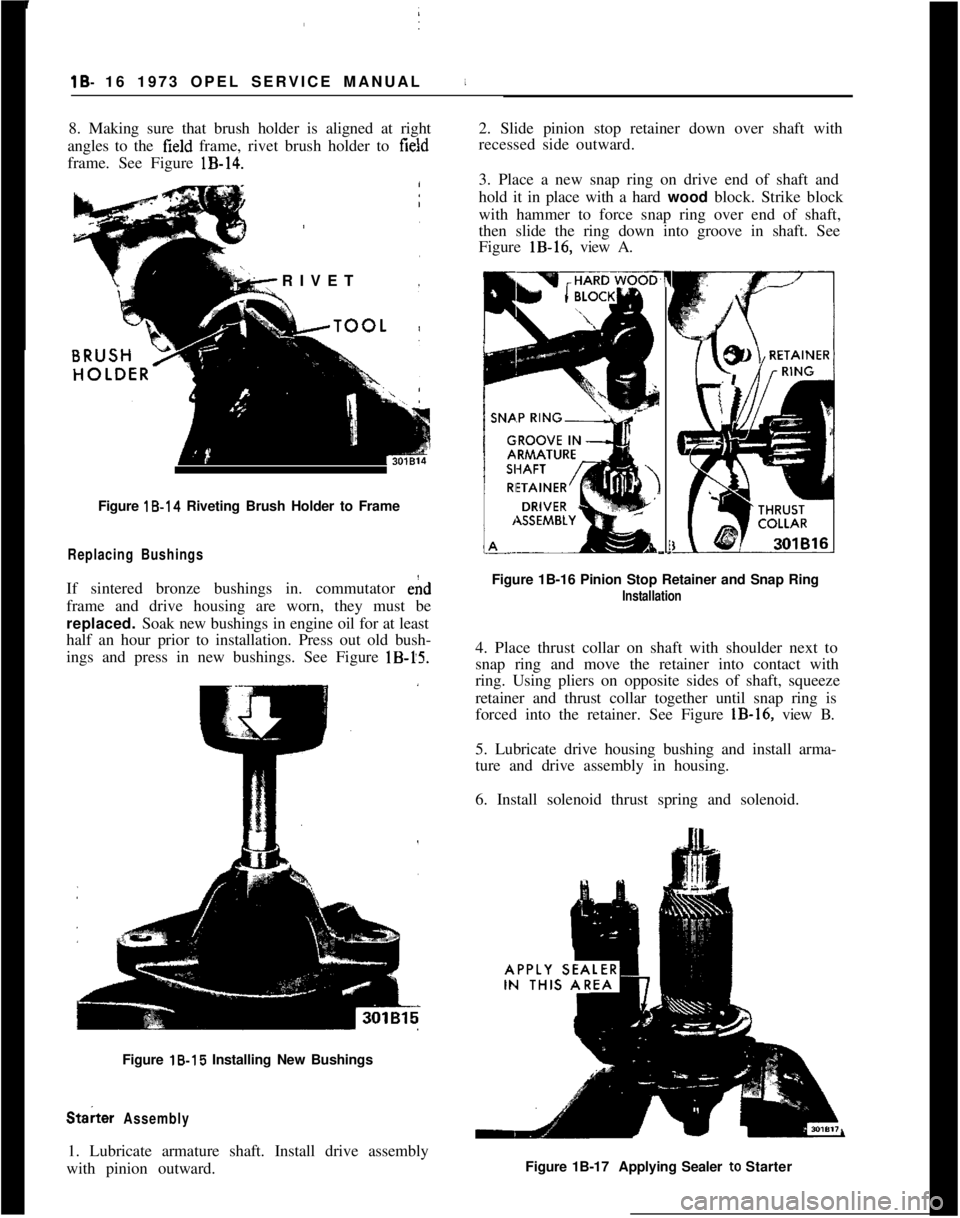
frame. See Figure
lB-14.
RIVET
Figure 18.14 Riveting Brush Holder to Frame i
Replacing Bushings
If sintered bronze bushings in. commutator ehd
frame and drive housing are worn, they must be
replaced. Soak new bushings in engine oil for at least
half an hour prior to installation. Press out old bush-
ings and press in new bushings. See Figure
lB-15.
Figure 18.15 Installing New Bushings
St& Assembly
1. Lubricate armature shaft. Install drive assembly
with pinion outward. 2. Slide pinion stop retainer down over shaft with
recessed side outward.
3. Place a new snap ring on drive end of shaft and
hold it in place with a hard
wood block. Strike block
with hammer to force snap ring over end of shaft,
then slide the ring down into groove in shaft. See
Figure
lB-16, view A.
7
(
I
I
E-.
Figure 1B-16 Pinion Stop Retainer and Snap Ring
Installation
4. Place thrust collar on shaft with shoulder next to
snap ring and move the retainer into contact with
ring. Using pliers on opposite sides of shaft, squeeze
retainer and thrust collar together until snap ring is
forced into the retainer. See Figure
lB-16, view B.
5. Lubricate drive housing bushing and install arma-
ture and drive assembly in housing.
6. Install solenoid thrust spring and solenoid.
Figure 1B-17 Applying Sealer to Starter
Page 47 of 625
lC- 261973 OPEL SERVICE MANUAL /
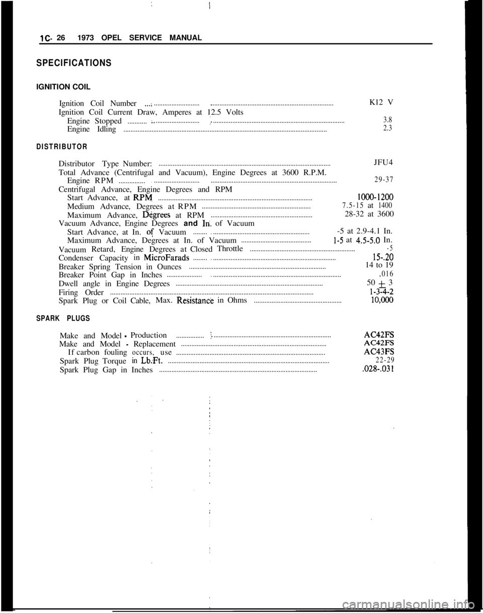
SPECIFICATIONSIGNITION COIL
Ignition Coil Number
.,.:.................................................................................................K12 V
Ignition Coil Current Draw, Amperes at 12.5 Volts
EngineStopped
...........:.........................._............................................................................3.8Engine Idling
....................................................................................................................2.3
DISTRIBUTORDistributor TypeNumber:
..................................................................................................JFU4
Total Advance (Centrifugal and Vacuum), Engine Degrees at 3600 R.P.M.
EngineRPM
..................................................................................................................29-37Centrifugal Advance, Engine Degrees and RPM
StartAdvance,atRPM
........................................................................................lOOO-1200MediumAdvance,DegreesatRPM
..............................................................7.5-15at1400Maximum Advance, Dkgrees at RPM
..........................................................28-32 at 3600
Vacuum Advance, Engine Degrees and
In. of Vacuum
Start Advance, at In. of Vacuum
................................................................-5 at 2.9-4.1 In.
Maximum Advance, Degrees at In. of Vacuum
........................................l-5 at 4.5-5.0 In.
VacuumRetard,EngineDegreesatClosedThrottle
............................................................-5CondenserCapacityinMicroFarads
...............................................................................15-.20Breaker Spring Tension in Ounces
..............................................................................14 to 19
Breaker Point Gap in Inches
..............................................................................................,016Dwell angle in Engine Degrees
....................................................................................50 + 3
Firing Order
....................................................................................................................l-32-2
SparkPlug or CoilCable,Max.Resistancti in Ohms
..................................................10,ooO
SPARK PLUGSMake and Model
-Production................I....................................................................AC42FS
Make and Model
- Replacement...................................................................................AC42FS
Ifcarbonfouling
occurs,use.....................................................................................AC43FS
SparkPlugTorqueinLb:Ft.
............................................................................................22-29Spark Plug Gap in Inches
...........................................................................................028-.03 1
Page 80 of 625

/
I
IINSTRUMENT PANELlH- 59
Figure 1 H-2
- GT Instrument and Switch Arrangement
The Wihdshield Wipers have two-speed operation.
By pushing the lower half of the switch inward to the
first stop, the wipers will operate at half speed and
by deprbssing to the second stop will provide full
speed oieration. When the switch is returned to the
off posit/on, the wiper blades automatically return to
their park position.
I
The El
this optlpn. The engine must be running before
suffi-cient current can be generated to energize this circuit
even th6ugh the switch is depressed to the “ON”
position! When the window is being heated, a warm-
ing light’on the instrument panel will glow. This light
is locate? below the left ventilation inlet.
The
Heiter Blower Switch is a three position switch.
By depressing the lower half of the switch to the first
stop,
th& blower will operate at low speed. Whendepressdd to the second stop, the blower will operate
at high ipeed.
Four Way Hezrerd Warning Flasher SwitchThe
hazard warning flasher switch is located below
the heater controls in the center console. By
depress-ing the lower half of the switch, all four turn- signal
lamps flash at the same time. Although this system
makes use of the regulat turn signal system, it has a
separate feed wire to the switch which allows for its
operation even with the ignition switch and doors
locked. No vehicle should be driven with this system
in operation because of its universal meaning “This
Vehicle Is Not Moving”. To turn the system off,
simply depress the upper half of the switch.
MAJOR REPAIR
Removal of Instrument Cluster Housing Assembly.Opel 1900 Manta
Before starting any instrument panel repair, always
disconnect battery ground cable first.
I
Page 93 of 625
1 J- 72 1973 OPEL SERVICE MANUAL
I
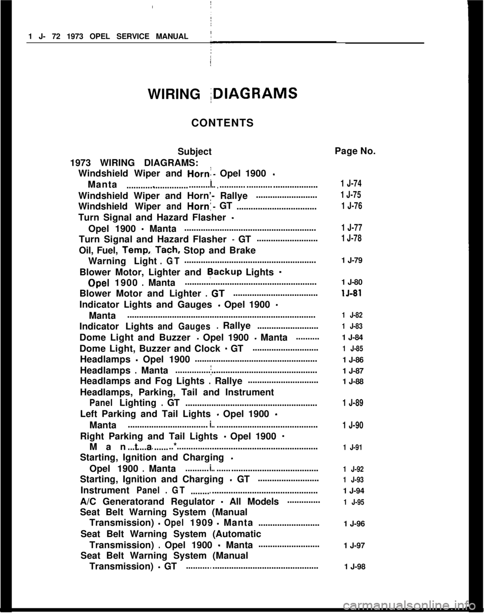
WIRING IDIAGRAMS
CONTENTS
Subject
1973 WIRING DIAGRAMS: Windshield Wiper and
Horn:- Opel 1900 -
Manta....................................I.............. ..............................
Windshield Wiper and Horn’- Rallye ..........................
Windshield Wiper
andHorn!-GT
..................................
Turn Signal and Hazard Flasher
-
Opel 1900 - Manta !
........................................................
Turn Signal and Hazard Flasher
- GT ..........................
Oil, Fuel,
Temp.: Tach, Stop and Brake
Warning Light
.GT........................................................
Blower Motor, Lighter and
Rackup Lights -
Qpel 1900.Manta ........................................................
Blower Motor and Lighter
.,GT....................................
Indicator Lights and Gauges
- Opel 1900 -
Manta ........................................................................\
........
Indicator Lights
andGauges.Rallye ..........................
Dome Light and Buzzer
- Opel 1900 - Manta..........
Dome Light, Buzzer and Clock - GT ............................
Headlamps
- Opel 1900 ’
....................................................
Headlamps
.Mantaj............................................................
Headlamps and Fog Lights
.Rallye ..............................
Headlamps, Parking, Tail and Instrument
PanelLighting.GT ........................................................
Left Parking and Tail Lights
- Opel 1900 -
Manta ..................................i.............................................
Right Parking and Tail Lights
- Opel 1900 -
Manta................. ..*............................................................
Starting, Ignition and Charging
-
Opel 1900.Manta..........i.............................................
Starting, Ignition and Charging
- GT ..........................
Instrument
Panel.GT ......................................................
A/C Generatorand Regulator
- All Models..............
Seat Belt Warning System (Manual Transmission)
-Opel1909-Manta ..........................
Seat Belt Warning System (Automatic Transmission)
.Opel 1900 - Manta..........................
Seat Belt Warning System (Manual Transmission)
- GT........................................................ Page No.
1 J-74
1 J-75
1 J-76
1 J-77
1 J-78
1 J-79
1 J-80
lJ-81
1 J-82
1 J-83
1 J-84
1 J-85
1 J-86
1 J-87
1 J-88
1 J-89
1 J-90
1 J-91
1 J-92
1 J-93
1 J-94
1 J-95
1 J-96
1 J-97
1 J-98
Page 225 of 625
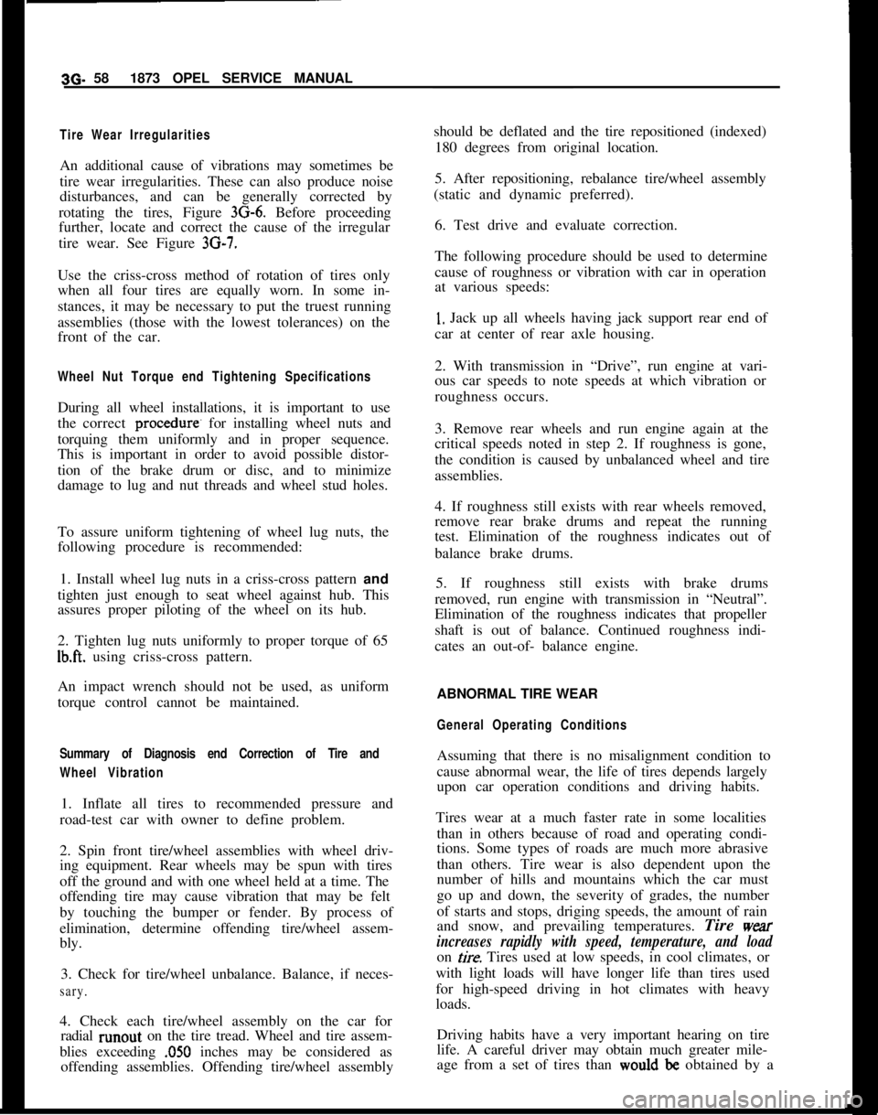
3G- 581873 OPEL SERVICE MANUALTire Wear IrregularitiesAn additional cause of vibrations may sometimes be
tire wear irregularities. These can also produce noise
disturbances, and can be generally corrected by
rotating the tires, Figure
3G-6. Before proceeding
further, locate and correct the cause of the irregular
tire wear. See Figure
3G-7.Use the criss-cross method of rotation of tires only
when all four tires are equally worn. In some in-
stances, it may be necessary to put the truest running
assemblies (those with the lowest tolerances) on the
front of the car.
Wheel Nut Torque end Tightening SpecificationsDuring all wheel installations, it is important to use
the correct procedures for installing wheel nuts and
torquing them uniformly and in proper sequence.
This is important in order to avoid possible distor-
tion of the brake drum or disc, and to minimize
damage to lug and nut threads and wheel stud holes.
To assure uniform tightening of wheel lug nuts, the
following procedure is recommended:
1. Install wheel lug nuts in a criss-cross pattern and
tighten just enough to seat wheel against hub. This
assures proper piloting of the wheel on its hub.
2. Tighten lug nuts uniformly to proper torque of 65
Ib.ft. using criss-cross pattern.
An impact wrench should not be used, as uniform
torque control cannot be maintained.
Summary of Diagnosis end Correction of Tire and
Wheel Vibration1. Inflate all tires to recommended pressure and
road-test car with owner to define problem.
2. Spin front tire/wheel assemblies with wheel driv-
ing equipment. Rear wheels may be spun with tires
off the ground and with one wheel held at a time. The
offending tire may cause vibration that may be felt
by touching the bumper or fender. By process of
elimination, determine offending tire/wheel assem-
bly.
3. Check for tire/wheel unbalance. Balance, if neces-
sary.4. Check each tire/wheel assembly on the car for
radial runout on the tire tread. Wheel and tire assem-
blies exceeding
.050 inches may be considered as
offending assemblies. Offending tire/wheel assemblyshould be deflated and the tire repositioned (indexed)
180 degrees from original location.
5. After repositioning, rebalance tire/wheel assembly
(static and dynamic preferred).
6. Test drive and evaluate correction.
The following procedure should be used to determine
cause of roughness or vibration with car in operation
at various speeds:
I. Jack up all wheels having jack support rear end of
car at center of rear axle housing.
2. With transmission in “Drive”, run engine at vari-
ous car speeds to note speeds at which vibration or
roughness occurs.
3. Remove rear wheels and run engine again at the
critical speeds noted in step 2. If roughness is gone,
the condition is caused by unbalanced wheel and tire
assemblies.
4. If roughness still exists with rear wheels removed,
remove rear brake drums and repeat the running
test. Elimination of the roughness indicates out of
balance brake drums.
5. If roughness still exists with brake drums
removed, run engine with transmission in “Neutral”.
Elimination of the roughness indicates that propeller
shaft is out of balance. Continued roughness indi-
cates an out-of- balance engine.
ABNORMAL TIRE WEAR
General Operating ConditionsAssuming that there is no misalignment condition to
cause abnormal wear, the life of tires depends largely
upon car operation conditions and driving habits.
Tires wear at a much faster rate in some localities
than in others because of road and operating condi-
tions. Some types of roads are much more abrasive
than others. Tire wear is also dependent upon the
number of hills and mountains which the car must
go up and down, the severity of grades, the number
of starts and stops, driging speeds, the amount of rain
and snow, and prevailing temperatures. Tire
wear
increases rapidly with speed, temperature, and loadon tire. Tires used at low speeds, in cool climates, or
with light loads will have longer life than tires used
for high-speed driving in hot climates with heavy
loads.
Driving habits have a very important hearing on tire
life. A careful driver may obtain much greater mile-
age from a set of tires than would be obtained by a
Page 339 of 625

6~. 46,1973 OPEL SERVICE MANUAL
ary barrel, it is provided with g transfer system.
When the secondary throttle valve starts to open,
two‘ports (which are normally just above the closed
valve) are uncovered, causing fuel to feed into the
secondary bore just before the secondary nozzle
starts feeding. This provides for an additional enrich-
ment of the air-fuel mixture at the beginning of full
throttle operation. See Figure
6E-7.
nInFlFigure
6E-7 Primary to Secondary Transfer System
Full Thrdttle Enrichment SystemIf the secondary throttle valve is fully opened, the
vacuum in the throttle valve area is reduced so that
the transfer ports (mentioned above) stop feeding.
However, the vacuum increases greatly in the sec-
ondary venturi area. An enrichment tube which pro-
trudes into the primary venturi area, feeds fuel
continuously during full throttle operation. See Fig-
ure
6E-2.
Acceleration SystemWhenever the throttle is closing, the suction stroke
of the diaphragm pump causes fuel to flow from the
float chamber through the inlet ball valve into the
pump chamber. When the throttle valve is opened
the diaphragm is moved inward by the pump con-
necting rod and the pump lever. Fuel is injected into
the primary bore through the injector tube. The
amount of fuel is determined by the pump stroke.
The inlet ball valve in the pump chamber prevents
fuel from flowing back into the float chamber during
the pressure stroke of the pump. The outlet ball valve
prevents air from being drawn into the injector tube
during the suction stroke of the pump. See Figure6E- 8.
Float Bowl VentilationWhile driving, the float bowl is ventilated from insideFigure
6E-8 Acceleration System
the carburetor. That is, the float bowl is connected
through the vent valve with the area under the air
cleaner.
When the engine is idling or off, the ventilation from
inside is cut off and ventilation from the charcoal
canister is cut in. The upper spring now seats the
valve on the upper seat. See Figure
6E-9.
-6E-9
Figure
6E-9 Float Bowl VentilationThe advantage of an inside vent while driving is that
air cleaner restriction does not enrichen the air fuel
mixture. The purpose of the charcoal canister vent
while idling or after shutting-off a hot engine, is to
prevent excess fuel vapors from entering the intakemanifold and outside air. Excess fuel vapors may
cause an idling engine to stall, or may make it dif-
ficult to restart a hot engine.
Page 342 of 625
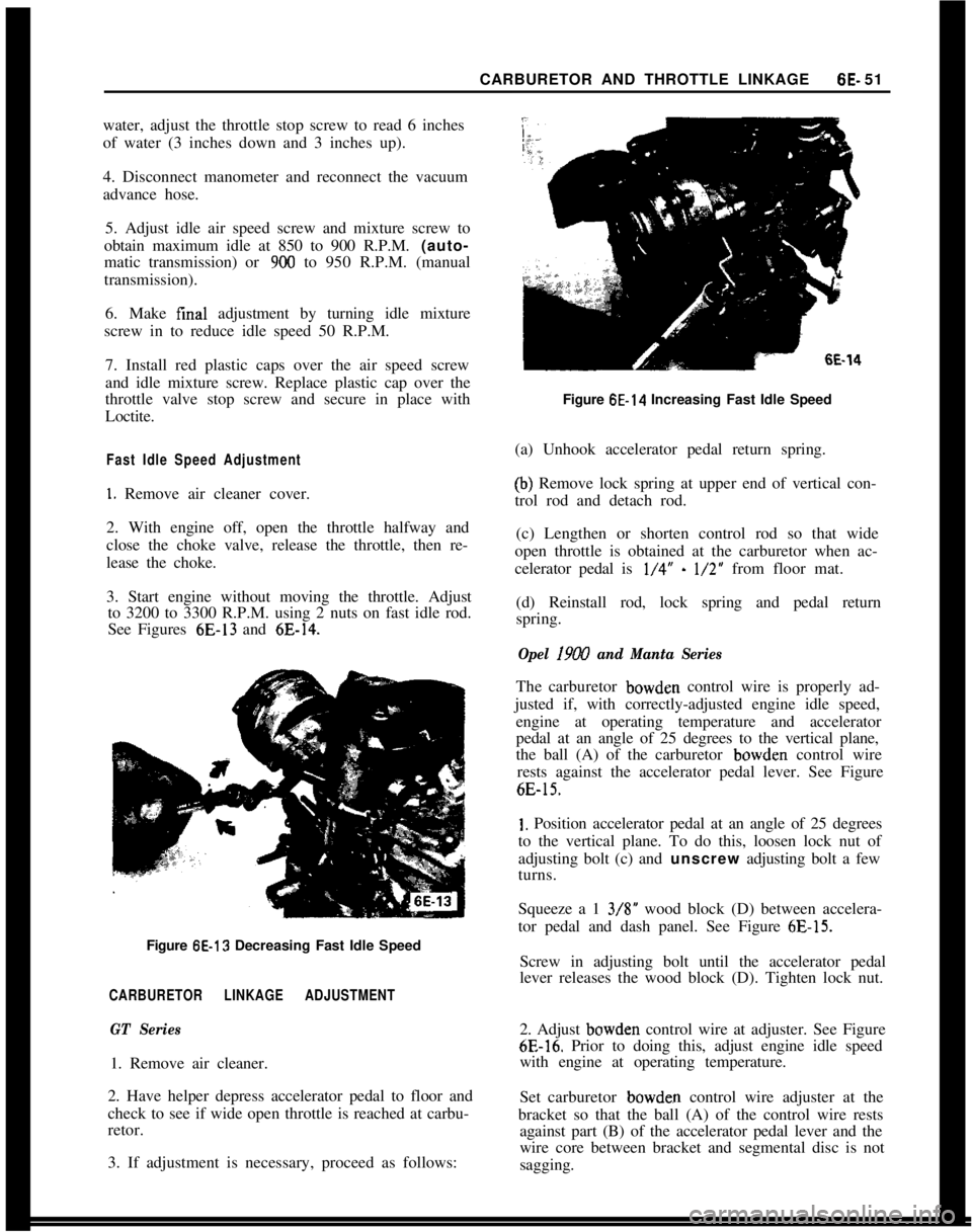
CARBURETOR AND THROTTLE LINKAGE6E- 51
water, adjust the throttle stop screw to read 6 inches
of water (3 inches down and 3 inches up).
4. Disconnect manometer and reconnect the vacuum
advance hose.
5. Adjust idle air speed screw and mixture screw to
obtain maximum idle at 850 to 900 R.P.M. (auto-
matic transmission) or 900 to 950 R.P.M. (manual
transmission).
6. Make final adjustment by turning idle mixture
screw in to reduce idle speed 50 R.P.M.
7. Install red plastic caps over the air speed screw
and idle mixture screw. Replace plastic cap over the
throttle valve stop screw and secure in place with
Loctite.
Fast Idle Speed Adjustment
1. Remove air cleaner cover.
2. With engine off, open the throttle halfway and
close the choke valve, release the throttle, then re-
lease the choke.
3. Start engine without moving the throttle. Adjust
to 3200 to 3300 R.P.M. using 2 nuts on fast idle rod.
See Figures 6E-13 and
6E-14.Figure
6E-13 Decreasing Fast Idle Speed
CARBURETOR LINKAGE ADJUSTMENT
GT Series1. Remove air cleaner.
2. Have helper depress accelerator pedal to floor and
check to see if wide open throttle is reached at carbu-
retor.
3. If adjustment is necessary, proceed as follows:
6E-14Figure
6E-14 Increasing Fast Idle Speed
(a) Unhook accelerator pedal return spring.
(b) Remove lock spring at upper end of vertical con-
trol rod and detach rod.
(c) Lengthen or shorten control rod so that wide
open throttle is obtained at the carburetor when ac-
celerator pedal is
l/4” - l/2” from floor mat.
(d) Reinstall rod, lock spring and pedal return
spring.
Opel 19W and Manta SeriesThe carburetor bowden control wire is properly ad-
justed if, with correctly-adjusted engine idle speed,
engine at operating temperature and accelerator
pedal at an angle of 25 degrees to the vertical plane,
the ball (A) of the carburetor bowden control wire
rests against the accelerator pedal lever. See Figure
6E-15.
1. Position accelerator pedal at an angle of 25 degrees
to the vertical plane. To do this, loosen lock nut of
adjusting bolt (c) and unscrew adjusting bolt a few
turns.
Squeeze a 1 3/S” wood block (D) between accelera-
tor pedal and dash panel. See Figure
6E-15.Screw in adjusting bolt until the accelerator pedal
lever releases the wood block (D). Tighten lock nut.
2. Adjust bowden control wire at adjuster. See Figure
6E-16. Prior to doing this, adjust engine idle speed
with engine at operating temperature.
Set carburetor bowden control wire adjuster at the
bracket so that the ball (A) of the control wire rests
against part (B) of the accelerator pedal lever and the
wire core between bracket and segmental disc is not
sagging.