stop start OPEL GT-R 1973 User Guide
[x] Cancel search | Manufacturer: OPEL, Model Year: 1973, Model line: GT-R, Model: OPEL GT-R 1973Pages: 625, PDF Size: 17.22 MB
Page 359 of 625
6G- 68 1973 OPEL SERVICE MANUAL
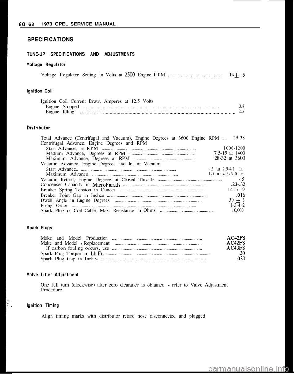
SPECIFICATIONS
TUNE-UP SPECIFICATIONS AND ADJUSTMENTS
Voltage Regulator
Voltage Regulator Setting in Volts at2500 Engine RPM. . . . . . . . . . . . . . . . . . . . . .14+.5
Ignition Coil
Ignition Coil Current Draw, Amperes at 12.5 Volts
Engine Stopped
. . . . . . . . . . . . . . . . . . . . . . . . . . . . . . . . . . . . \
. . . . . . . . . . . . . . . . . . . . . . . . . . . . . . . . . . . . \
. . . . . . . . . . . . . . . . . . . . . . . . . . . . . . . . . . . . \
. . . . . .3.8
EngineIdling. . . . . . . . . . . . . . . . . .._.....................................................................\
........................... 2.3
Total Advance (Centrifugal and Vacuum), Engine Degrees at 3600 Engine \
RPM......29-38
Centrifugal Advance, Engine Degrees and RPM
Start Advance, atRPM
........................................................................\
................ 1000-1200
Medium Advance, Degrees at RPM..............................................................7.5-15 at 1400
Maximum Advance, Degrees at RPM
..........................................................28-32 at 3600
Vacuum Advance, Engine Degrees and In. of Vacuum Start Advance..
........................................................................\
.................-5at2.9-4.1 In.
Maximum Advance..........................................................................\
........1-5at4.5-5.0In.
Vacuum Retard, Engine Degrees at Closed Throttle............................................................-5
Condenser Capacity in
MicroFarads........................................................................\
.......23-.32
Breaker Spring Tension in Ounces........................................................................\
......14 to 19
Breaker Point Gap in Inches
........................................................................\
......................,016
Dwell AngleinEngine Degrees........................................................................\
.......... 50+3
Firing
Order........................................................................\
............................................l-3-4-2
Spark Plug or Coil Cable,Max.Resistance in Ohms
..................................................
10,000
Spark Plugs
Make and Model Production........................................................................\
............AC42FS
Make andModel
-Replacement........................................................................\
..........AC42FS
If carbon fouling occurs, use
........................................................................\
............AC43FS
Spark Plug Torque in
Lb.Ft.........................................................................\
.........................30
Spark Plug Gap in Inches........................................................................\
..........................,030
Valve Lifter Adjustment
One full turn (clockwise) after zero clearance is obtained - refer to Valve Adjustment
Procedure
Ignition Timing
Align timing marks with distributor retard hose disconnected and plugged\
Page 399 of 625
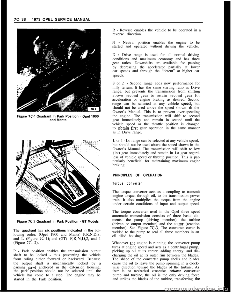
Figure 7C-1 Quadrant In Park Position -Opel 1900
and Manta7C- 381973 OPEL SERVICE MANUAL
R
- Reverse enables the vehicle to be operated in a
reverse direction.
N
- Neutral position enables the engine to be
started and operated without driving the vehicle.
D
- Drive range is used for all normal driving
conditions and maximum economy and has three
gear ratios. Downshifts are available for passing
by depressing the accelerator partially at lower
car speeds and through the “detent” at higher car
speeds.
S or 2
- Second range adds new performance for
hilly terrain. It has the same starting ratio as Drive
range, but prevents the transmission from shifting
above second gear to retain second gear for
acceleration or engine braking as desired. Second
range can be selected at any vehicle speed, but
should not be used above the speed shown m the
Owner’s Manual. This is to prevent over-speeding
the engine. The transmission will shift to second
gear immediately and remain in second until the
vehicle speed or the throttle position is changed
to obtajn first gear operation in the same manner
as in Drive range.
L or 1
- Lo range can be selected at any vehicle speed,
but should not be used above the speed shown in the
Owner’s Manual. The transmission will shift to low
(1st) gear immediately and remain in 1st gear regard-
less of vehicle speed or throttle position. This is par-
ticularly beneficial for maintaining maximum engine
braking.
PRINCIPLES OF OPERATION
Torque ConverterThe torque converter acts as a coupling to transmit
engine torque, through oil, to the transmission power
train. It also multiplies the torque from the engine
under certain conditions of input and output speed.
Figure
7C-2 Quadrant in Park Position - GT Models
The quadrant has six positions indicated in the fol-
lowing order: (Opel 1900 and Manta) P,R,N,D,S,
and L (Figure
7C-1); and (GT) P,R,N,D,2, and 1
(Figure 7C- 2).The torque converter used in the Opel three speed
automatic transmission consists of three basic ele-
ments: the pump (driving member), the turbine
(driven or output member) and the stator (reaction
member). See Figure
7C-3. The converter cover is
welded to the pump to seal all three members in an
oil tilled housing.
P
- Park position enables the transmission output
shaft to be locked
- thus preventing the vehicle
from roling either forward or backward. Because
the output shaft is mechanically locked by a
parking
paw1 anchored in the extension housing,
the park position should not be selected until the
vehicle has come to a stop. The engine may be
started in the Park position.Whenever the engine is running, the converter pump
turns at engine speed and acts as a centrifugal pump,
picking up oil at its center, adding energy, and dis-
charging the oil at its outer rim between the blades.
The shape of the converter pump shells and blades
cause the oil to leave the pump spinning in a clock-
wise direction toward the blades of the turbine. Asthere is no mechanical connection between converterpump and turbine, the oil is the only driving force
and strikes the blades of the turbine, transferring the
Page 528 of 625
REFRIGERANT COMPONENTS ALL MODELS9s. 19
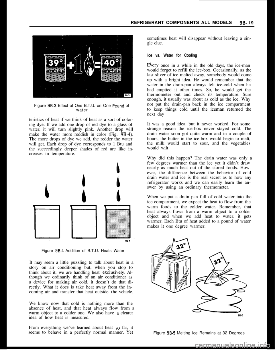
Figure 98.3 Effect of One B.T.U. on One
Pc’und of
water
teristics of heat if we think of heat as a sort of color-
ing dye. If we add one drop of red dye to a glass of
water, it will turn slightly pink. Another drop will
make the water more reddish in color (Fig.
9B-4).The more drops of dye we add, the redder the water
will get. Each drop of dye corresponds to 1 Btu and
the succeedingly deeper shades of red are like in-
creases in temperature.
Figure
98-4 Addition of B.T.U. Heats Water
It may seem a little puzzling to talk about beat in a
story on air conditioning but, when you stop to
think about it, we are handling heat exclusively. Al-
though we ordinarily think of an air conditioner as
a device for making air cold, it doesn’t do that di-
rectly. What it does is take heat away from the in-
coming air and transfer that heat outside the vehicle.
We know now that cold is nothing more than the
absence of heat, and that heat always flow from a
warm object to a colder one. We also have
:a clearer
idea of how heat is measured.
From everything we’ve learned about heat
EO far, it
seems to behave in a perfectly normal manner. Yetsometimes heat will disappear without leaving a sin-
gle clue.
Ice vs. Water for CoolingEtery once in a while in the old days, the ice-man
would forget to refill the ice-box. Occasionally, as the
last sliver of ice melted away, somebody would come
up with a bright idea. He would remember that the
water in the drain-pan always felt ice-cold when he
had emptied it other times. So, he would get the
thermometer out and check its temperature. Sure
enough, it usually was about as cold as the ice. Why
not put the drain-pan back in the ice compartment
to keep things cold until the iceman returned the
next day
It was a good idea. but it never worked. For some
strange reason the ice-box never stayed cold. The
drain water soon got quite warm and in a couple of
hours, the butter in the ice-box would begin to melt,
the milk would start to sour, and the vegetables
would wilt.
Why did this happen? The drain water was only a
few degrees warmer than the ice yet it didn’t draw
nearly as much heat out of the stored foods. How-
ever, the difference between the behavior of cold
drain water and ice is the real secret as to how any
refrigerator works and we can easily learn the an-
swer by using an ordinary thermometer.
When we put a drain pan full of cold water into the
ice compartment, we expect the heat to flow from the
warm foods to the colder water. Remember, that
heat always flows from a warm object to a colder
object and when we add heat to water, it gets
warmer. Each Btu of heat added to a pound of water
makes it one degree warmer.
Figure 98.5 Melting Ice Remains at 32 Degrees
Page 535 of 625
98-26 1973 OPEL SERVICE MANUAL
greater than the opposing pressure in the power ele-
ment. Therefore, the valve remains closed. When the
compressor is started, it will reduce the pressure and
temperature of the refrigerant in the cooling coil to
a point where the vapor pressure in the power ele-
ment becomes the stronger. The seat then moves off
the orifice and liquid starts to flow through the valve
orifice into the cooling coil.
The purpose of the power element is to help deter-
mine the quantity of liquid that is being metered into
the cooling coil. As the temperature of the low pres-
sure line changes at the bulb, the pressure of
the
vapor in the power element changes, resulting in a
change of the position of the seat. For example, if the
cooling coil gets more liquid than is required, the
temperature of the low pressure line is reduced and
the resultant lowering of the bulb temperature
reduces the pressure of the vapor in the power ele-
ment, allowing the seat to move closer to the orifice.
This immediately reduces the amount of liquid leav-
ing the valve. Under normal operation, the power
element provides accurate control of the quantity of
refrigerant to the cooling coil.
To employ our tire pump analogy once more for
clarity, it is the same situation that would exist if you were inflating a tire with a very slow leak. Providing
you pumped the air into the tire as fast as it leaked
out, you would be able to maintain pressure even
though the air would merely be circulating through the tire and leaking out through the puncture.
To Sum Up
So far, we’ve discussed only what each unit in an air
conditioning system does. We’ve learned that the
evaporator is the unit in which liquid refrigerant
soaks up heat from the air, the compressor is a pump
for squeezing this heat out of the vapor, the con-
denser is a radiator for getting rid of the heat, and the
thermostatic expansion valve is a device for regulat-
ing the pressure on the refrigerant. Now, let’s
find
out how the temperature of the cooled air is con-
trolled.
METHOD OF TEMPERATURE CONTROL
To achieve temperature control, the compressor is
run intermittently, automatically turning on and off
as necessary to maintain proper temperature.
Thermostatic Switch
The compressor can be started and stopped au-
tomatically through the use of an electro-magnetic
clutch and a thermostat affected by variations of temperature.
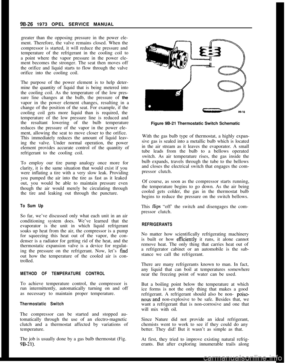
The job is usually done by a gas bulb thermostat (Fig.
9B-21).
Figure 9B-21 Thermostatic Switch Schematic
With the gas bulb type of thermostat, a highly expan-
sive gas is sealed into a metallic bulb which is located
in the air stream as it leaves the evaporator. A small
tube leads from the bulb to a bellows operated switch. As air temperature rises, the gas inside the
bulb expands, travels through the tube to the bellows
and closes the electrical switch that engages the com-
pressor clutch.
Of course, as soon as the compressor starts running,
the temperature begins to go down. As the air being
cooled gets colder, the gas in the thermostat bulb
begins to reduce the pressure on the switch bellows.
This
Ilips “off’ the switch and disengages the com-
pressor clutch.
REFRIGERANTS
No matter how scientifically refrigerating machinery
is built or how
efftciently it runs, it alone cannot
remove heat. The only thing that carries heat out of
a refrigerator cabinet or an automobile is the sub-
stance we call the refrigerant.
There are many refrigerants known to man. In fact,
any liquid that can boil at temperatures somewhere
near the freezing point of water can be used.
But a boiling point below the temperature at which
ice forms is not the only thing that makes a good
refrigerant. A refrigerant should also be non-
poiso-
nowand non-explosive to be safe. Besides that, we
want a refrigerant that is non-corrosive and one that
will mix with oil.
Since Nature did not provide an ideal refrigerant,
chemists went to work to see if they could do any
better. They did! But it wasn’t as simple as that.
At first, they tried to improve existing natural refrig-
erants. But after exploring innumerable trails along
Page 540 of 625
REFRIGERANT COMPONENTS ALL MODELS9B- 31
When adding oil, the container should be exception-
ally clean and dry due to the fact that the refrigera-
tion oil in the container is as moisture-free as it is
possible to make it. Therefore, it will quickly absorb
any moisture with which it comes in contact. For this
same reason the oil container should not be opened
until ready for use and it should be capped immedi-
ately afte;r use.
When it is necessary to open a system, have every-
thing you will need ready and handy so that as little
time as possible will be required to perform the oper-
ation. Don’t leave the system open any longer than
is necessary.
Finally, after the operation has been completed and
the system sealed again, air and moisture should be
evacuated from the system before recharging.
THE PRIMARY CAUSES OF SYSTEM FAILURES
LeaksA shortage of refrigerant causes oil to be trapped in
the evaporator. Oil may be lost with the refrigerant
at point of leakage. Both of these can cause compres-
sor seizure.
Oil circulates in the system with the refrigerant; in
solution with the liquid and in globules with the
vapor. It leaves the compressor by the action of the
pistons and mixes with the refrigerant liquid in the
condenser. The oil then enters the evaporator with
the liquid and, with the evaporator properly flooded,
is returned to the compressor through the low pres-
sure line. Some of the oil returns as globules in the
vapor, but more important, it is swept as a liquid
along the walls of the tubing by the velocity of the
vapor. If the evaporator is starved, the oil cannot
return in sut?icient quantities to keep the compressor
properly lubricated.
High Temperature and PressureAn increase in temperature causes an increase in
pressure. This accelerates chemical instability due to
existing contaminants in the system, and initiates
chemical instability in clean systems. Other results
are brittle hoses,
“0” ring gaskets, and valve dia-
phragms with possible decomposition, broken com-
pressor discharge reeds, and seized compressor
bearings.
A fundamental law of nature accounts for the fact
that when a substance, such as a refrigerant, is in-
creased in temperature, its pressure is also increased.
Any chemical reactions caused by contaminants al-
ready in the system are greatly accelerated as the
temperature increases. A 15 degree rise in tempera-
ture doubles the chemical action. Even in a goodclean system, heat alone can start a chain of harmful
chemical reactions.
While temperature alone can cause the synthetic rub-
ber parts to become brittle and possibly to decom-
pose, the increased pressure can cause them to
rupture or blow.
As the temperature and pressure increases the stress
and strain on the compressor discharge reeds also
increases. This can result in broken reeds. Due to the
effect of the contaminants caused by high tempera-
ture and pressure, compressor bearings can be
caused to seize.
High temperature and pressure are also caused by air
in the system.
Air in the SYstemAir results from a discharged system or careless ser-
vicing procedures. This reduces system capacity and
efficiency and causes oxidation of oil into gum and
varnish.
When a leak causes the system to become dis-
charged, the resulting vacuum within the system will
cause air to be drawn in. Air in the system is a
non-condensable gas and will build up in the con-
denser as it would in an air compressor tank. The
resultant heat produced will contribute to the condi-
tions discussed previously.
Many systems are contaminated and also reduced in
capacity and efficiency by servicemen who either do
not know or are careless regarding proper servicing
procedures.
Too frequently, systems which have been open to the
atmosphere during service operations have not been
properly purged or evacuated. Air is also introduced
into the system by unpurged gauge and charging
lines. Remember that any air in the system is too
much air.
Poor ConnectionsHose clamp type fittings must be properly made.
Hoses should be installed over the sealing flanges and
with the end of the hose at the stop flange. The hose
should never extend beyond the stop flange. Locate
the clamp properly and torque as recommended. Be
especially careful that the sealing flanges are not
nicked or scored or a future leak will result.
When compression fittings are used, over tightening
can cause physical damage to the “0” ring gasket
and will result in leaks. The use of torque and back-
ing wrenches is highly recommended. When making
a connection with compression fittings, the gaskets
should always be first placed over the tube before
Page 552 of 625
REFRIGERANT COMPONENTS ALL MODELS9B- 43
4. Start the vacuum pump and slowly open low and
high pressure sides of manifold gauge set to avoid
forcing oil out of refrigeration system and pump,
Pressure is now being reduced on both sides of the
refrigeration system. If oil is blown from the vacuum
pump, it should be refilled to the proper level.
5. Observe low pressure gauge and operate vacuum
pump until gauge shows 28-29 inches vacuum. In all
evacuating procedures, specifications of 28-29 inchesof vacuum is used. This evacuation can only be at-
tained at or near sea level.
For each 1000 feet above sea level where this operat-ion is being-performed, the specification should be
lowered by one inch of mercury vacuum. At 5000
feet elevation, only 23 inches to 24 inches of vacuum
can normally be obtained.
If vacuum cannot be pulled to the minimum specifi-
cation for the respective altitude, it indicates a leak
in the system or gauge connections or a defective
vacuum pump. In this case, it will be necessary to
check for leaks as described under “Leak Testing
Refrigerant System”.
When specified vacuum level (28-29 inches at sea
level) is obtained, continue to run vacuum pump for
ten (10) ‘additional minutes. During these ten (10)
minutes:
A. Prepare for charging the system. If using a charg-
ing station, till charging cylinder. If using manifold
gauge set, make all preparations for charging system
as described under “Disposable Can Method” or
“Refrigerant Drum Method”.
B. Measure oil loss collected as a result of rapid
discharge.
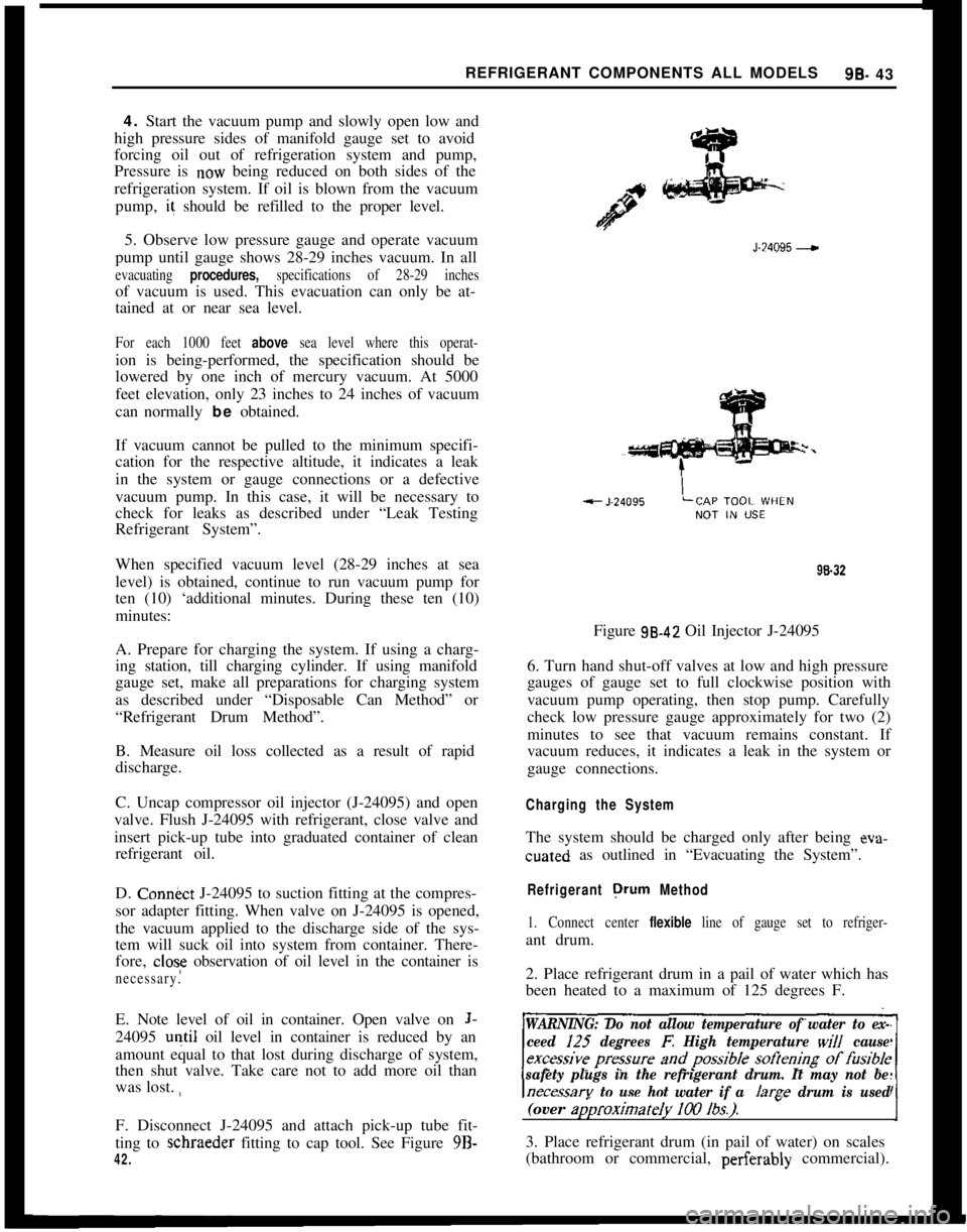
C. Uncap compressor oil injector (J-24095) and open
valve. Flush J-24095 with refrigerant, close valve and
insert pick-up tube into graduated container of clean
refrigerant oil.
D. Con&ct J-24095 to suction fitting at the compres-
sor adapter fitting. When valve on J-24095 is opened,
the vacuum applied to the discharge side of the sys-
tem will suck oil into system from container. There-
fore,
close observation of oil level in the container is
necessary.E. Note level of oil in container. Open valve on
J-24095
u+il oil level in container is reduced by an
amount equal to that lost during discharge of system,
then shut valve. Take care not to add more oil than
was lost. ,,
F. Disconnect J-24095 and attach pick-up tube fit-
ting to schraeder fitting to cap tool. See Figure 9B-
42.J-24095
-98.32
Figure 98.42 Oil Injector J-24095
6. Turn hand shut-off valves at low and high pressure
gauges of gauge set to full clockwise position with
vacuum pump operating, then stop pump. Carefully
check low pressure gauge approximately for two (2)
minutes to see that vacuum remains constant. If
vacuum reduces, it indicates a leak in the system or
gauge connections.
Charging the SystemThe system should be charged only after being eva-cuated as outlined in “Evacuating the System”.
Refrigerant orurn Method
1. Connect center flexible line of gauge set to refriger-ant drum.
2. Place refrigerant drum in a pail of water which has
been heated to a maximum of 125 degrees F.
WARNING: Do not allow temperature of water to ex-
ceed I25
degrees E High temperature will cause
safety plugs in the refrigerant drum. It may not be
necessarv to use hot water if a /arae drum is used(over
ap)roximateIy 100 lbs.).-I3. Place refrigerant drum (in pail of water) on scales
(bathroom or commercial, perferably commercial).
Page 553 of 625
9B-44 1973 OPEL SERVICE MANUAL
Do not turn refrigerant drum upside down, as this
would allow liquid refrigerant to enter compressor
which may cause damage.
4. If line at center gauge fitting has not been purged
of air, loosen line at center fitting on gauge set and
crack valve on refrigerant drum to blow air from
line. Retighten line at center fitting and record exact
weight of refrigerant tank in water on the scales.
5. Open valve on refrigerant drum and both valves
on gauge set to allow refrigerant to flow into system.
Continue charging until the scales show that 2
Ibs.Opel 1900
- Manta and 2 l/4 lbs. GT, of refrigerant
have been transferred from refrigerant drum to sys-
tem.If full charge cannot be obtained, close both valves
on gauge set, start engine, and set temperature con-
trol knob to full cold position with blower in Max Hi.
Open low pressure valve on gauge set slowly and
leave open until full charge is added.
WARNING: Observe high pressure gauge while charg-
ing with compressor running. Shut
offengine ifpres-
sure exceeds 250 psi. A large fan placed in front
ol
the car wi// help reduce excessively high head pres-6. Close both valves on gauge set (high pressure valve
will already be closed if charging was completed by
running compressor) and close valve on refrigerant
drum.
If the engine was used to complete the charge into
the system, close valve on refrigerant drum to permit
compressor to draw any refrigerant left in the line
from the drum to the center fitting of the gauge set,
then close the low pressure valve on the gauge set.
7. Operate engine at 2000 RPM with temperature
control knob at full cold, blower speed in Max Hi.
After ten minutes of operation, observe appearance
of refrigerant in receiver-dehydrator. If bubbles are
observed, open low pressure gauge valve and valve
on refrigerant drum to allow more refrigerant to en-
ter system. Close valve when receiver-dehydrator
clears
up.If an air inlet temperature is below 70 degrees F.
when this check is made, bubbles may appear, even
though the proper amount of refrigerant is in the
system. Air inlet temperature must be 70 degrees F.
or above to make an accurate check.
8. When refrigerant has been installed, continue to
operate system and test for proper operation as ou-
tlined under “Operational Test”.
9. When satisfied that air conditioning system is op-
erating properly, stop engine, remove gauge set and
replace protective caps on compressor fittings.10. Using leak detector, check complete system for
leaks.Disposable Can Method
After having
depress&ed, repaired (if necessary)
and evacuated the refrigerant system, the system
may be charged as follows using refrigerant in dis-
posable cans:
1. Obtain three (3) 1
lb. cans or one 12 lb. can of
refrigerant.
2. If using 1 lb. cans, mount two (2) cans in J-6272-
02 (Multi-opener) or attach J-6271 (single-can
opener valve) on one can. If using the 12
lb. disposa-
ble can, attach J-23390 (disposable can control valve)
on can.WARNING: Make sure outlet valve on opener is
closed (clockwise) before installing opener.A. If the J-6272-02 multi-opener is used, raise lock-
ing lever, position three (3) cans of refrigerant and
force locking lever down to secure cans and at same
time puncture top of can to make it ready for charg-
ing.
B. If the J-6271 valve is used, back off the valve from
the can top retainer, slip the valve onto the can and
turn the valve into retainer until tight. DO NOT
open outlet valve during this operation, as turning
the valve into the retainer punctures top of can to
make it ready for charging.
3. Connect center flexible line of gauge set to fitting
on a can opener valve. If the line at center gauge
fitting has not been purged of air, loosen line at
center fitting on gauge set and “crack” valve at can
opener (for a second or two) to force air from the
line. Retighten line at center fitting.
4. Open valve at refrigerant source and at low and
high pressure valves on manifold gauge set. Leave
valve open at refrigerant source until all refrigerant
(when using 1 lb. can) has ‘entered the refrigeration
system or system is fully charged. Close valve on can.
A. If the system is charged using
1 lb. cans and the
J- 627 1 valve, disconnect valve from can. Leave valve
closed to flexible line to the center fitting of the
manifold gauge set. Install valve on a new and full
disposable can of refrigerant.
Page 554 of 625
REFRIGERANT COMPONENTS ALL MODELS9t3- 45
B. If system is charged using J-6272-02, close the
valve of opener after all cans are empty. Release the locking lever and discard the three (3) empty cans.
If this tool will be used to complete the charge with
additional cans to provide the required refrigerant
charge, leave the empty cans in position, locate one
full can and lock the lever into place. These empty
cans balance the assembly and prevent the loss of
refrigerant through the open “series” passage. Align
the pierced hole in the empty can with the punch in
the cover of the tool.
If the J-6271 valve for single cans is available, com-
plete charging as explained in 4a above.
5. Close high side valve on manifold gauge set,
WARNING: Prior to starting up engine, the high side
valve on the charging manifold must be closed due
to excessive pressure
bui/d-up which can result in
bursting of the container(s) causing serious injury. If
you are inexperienced in the use of this procedure, seek professional assistance.
6. Operate engine at 2000 RPM with temperature
control knob at full cold position and blower speed
on Max Hi. If air inlet temperature at the condenser
is below 70 degrees F. when this check is made,
bubbles may appear, even though the proper amount
of refrigerant is in the system. Air inlet temperature
must be 70 degrees F. or above to make an accurate
check.
7. When refrigerant has been installed, continue to
operate system and test for proper operation as ou-
tlined
under “Operational Test”.
8. When satisfied that the air conditioning system
is operating properly, stop engine, remove gauge set
and replace protective caps on suction and discharge
fittings.
from thegauge fitting to prevent damage-or injury to
personnel.
9. Using a leak detector, check complete system for
leaks.
Charging Station Method
INSTALLING J-8393-02
-
1. Be ceitain compressor hand shut-off valves to
gauge fittings are closed (counterclockwise).
2. Be certain all valves on charging station are
closed.
3. Connect high pressure gauge line to compressor
high pressure gauge fitting.
4. Turn high pressure hand shut-off valve one turn
clockwise, and high pressure control one turn coun-
terclockwise (open). Crack open low pressure con-
trol and allow refrigerant gas to hiss from low
pressure gauge line for three seconds, then connect
low pressure gauge line to low pressure gauge fitting
on compressor adapter fitting. (Place J-9459 adapter
on hose, then attach adapter to gauge fitting.)
FILLING CHARGING CYLINDER
1. Open Control valve on refrigerant container.
2. Open valve on bottom of charging cylinder, al-
lowing refrigerant to enter cylinder.
3. Bleed charging cylinder to valve (behind control
panel) only as required to allow refrigerant to enter
cylinder. When refrigerant reaches desired charge
level, close valve at bottom of charging cylinder and
be certain cylinder bleed valve is closed securely.
While filling the cylinder, it will be necessary to close
the bleed valve periodically to allow boiling to sub-
side so that refrigerant level in the charging cylinder
can be accurately read.
CHARGING THE SYSTEM USING J-8393-02
1. With charging station connected, as previously
described, remove low pressure gauge line at com-
pressor adapter fitting.
2. Crack open high and low pressure control valves
on station and allow refrigerant gas to purge from
system. Purge slowly enough so, that oil does not
escape from system along with refrigerant.
3. When refrigerant flow nearly stops, connect low
pressure gauge line to
compress& adapter fitting.
4. Turn on vacuum pump and open vacuum control
valve.
5. With system purged as
abovk, run pump until
26-28 inches of vacuum is obtained Continue to run
pump for 15 minutes after the system reaches 26-28
inches vacuum.
In all evacuating procedures, the specification of
26.
28 inches of mercury vacuum is used. These figures
are only attainable at or near sea level. For each 1000
feet above sea level where this operation is being
performed, the specifications should be lowered by 1
inch. For example, at 5000 feet elevation, only 21 to
23 inches vacuum can normally be obtained.
6. If 26-28 inches vacuum (corrected to sea level)
cannot be obtained, close vacuum: control valve and