ESP OPEL GT-R 1973 Service Manual
[x] Cancel search | Manufacturer: OPEL, Model Year: 1973, Model line: GT-R, Model: OPEL GT-R 1973Pages: 625, PDF Size: 17.22 MB
Page 5 of 625
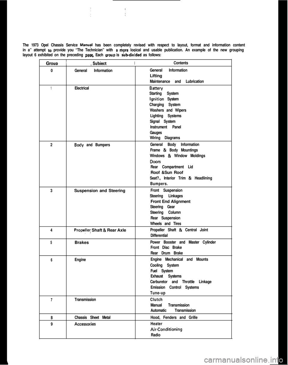
The 1973 Opel Chassis Service MayI has been completely revised with respect to layout, format and information content
in a” attempt
to provide you “The Technician” with a tiore logical and usable publication. An example of the new grouping
layout 6 exhibited on the preceding
page. Each wow is rubdivided as follows:
Grouo 1
_. _
Subiect IIContents.
0
General InformationIGeneral InformationLifting
Maintenance and Lubrication
1ElectricalBattery
Starting System
lgriition System
Charging System
Washers and Wipers
Lighting Systems
Signal SystemI
Instrument Panel
Gauges
Wiring Diagrams
2
Body and Bumpers:General Body InformationI
Frame & Body Mountings
Windows
& Window Moldings
DONS
Rear Compartment LidRoof &Sun Roof
Seat?., Interior Trim & Headlining
Bumpers.
3Suspension and Steering
Front Suspension
Steering Linkages1Front End Alignment
Steering Gear
Steering Column
Rear Suspension
Wheels and Tires
4
Propelley Shaft & Rear AxlePropeller Shaft & Central Joint
Differential
5Brakes ~Power Booster and Master Cylinder
Front Disc BrakeI
Rear Drum Brake
6EngineEngine Mechanical and Mounts
Cooling System
Fuel System
Exhaust Systems
Carburetor and Throttle Linkage
Emission Control Systems
Tune-up
7TransmissionClutch
Manual Transmission
Automatic Transmission
BChassis Sheet MetalHood, Fenders and Grille
9
Accessol;iesHeaterAirConditioning
Radio
Page 6 of 625
INTRODUCTION
The 1973 Opel Service Manual includes information on the Opel 1900,
Manta and GT. It is organized to correspond with current servicing tech-
niques. The various chassis components and systems have been classified
into the nine (9) GROUPS.Every GROUP contains one or more SECTIONS. Each SECTION deals with aspecific version of a component or system.
The service information included in a SECTION is divided into five (5) basic
DIVISIONS. The titles of each DIVISION are:
Description and Operation
Trouble Diagnosis
Maintenance and Adjustments
Major Repair
SpLificaiions
A DIVISION contains one or more PARAGRAPHS which can be identified bytheir specific headings.
SUB-PARAGRAPHS are used when necessary for clarity or to provide distinc-tion between component procedures.
SPECIAL TOOLS
References are made throughout the Manual to special tool numbers, desig-nated by the prefix letter “J”. These tools are manufactured by the
Kent-
Moore Corporation, Inc. If equivalent special tools are not available locally,they may be obtained through:
Kent-Moore Corporation, Inc.
28635 Mound Road
Warren, Michigan 46092LOCATING DESIRED INFORMATION
To locate any desired information, locate the proper GROUP listed on the
second page of the Manual. Bend the Manual until the black tab on the first
page of the GROUP can be seen in line with the GROUP title on the secondpage. The first page of the GROUP lists the SECTIONS contained therein.
Turn to the proper SECTION, locate the desired DIVISION and note the
PARAGRAPH containing the information you are seeking.
Page 17 of 625
IoC-91973 OPEL SERVICE MANUAL
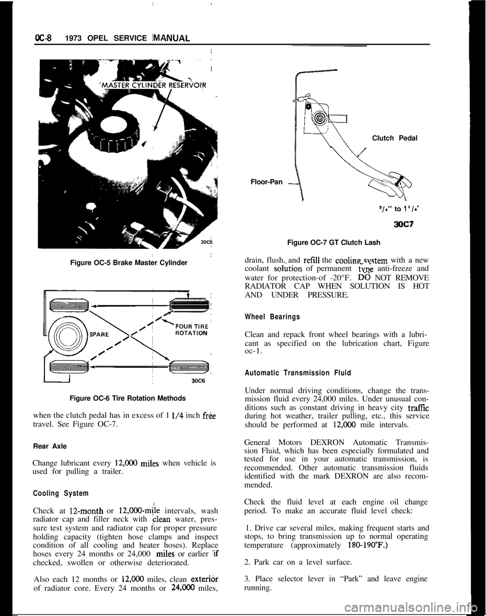
Figure OC-5 Brake Master Cylinder
I
Figure OC-6 Tire Rotation Methods
when the clutch pedal has in excess of 1
l/4 inch fr&
travel. See Figure OC-7.
Rear Axle
Change lubricant every
12,ooO miies when vehicle is
used for pulling a trailer.
Cooling SystemCheck at 12-month or
12,000~mile intervals, wash
radiator cap and filler neck with clean water, pres-
sure test system and radiator cap for proper pressure
holding capacity (tighten hose clamps and inspect
condition of all cooling and heater hoses). Replace
hoses every 24 months or 24,000 ,miles or earlier :if
checked, swollen or otherwise deteriorated.
Also each 12 months or
12,ooO miles, clean exteribr
of radiator core. Every 24 months or
24,OCO miles,Floor-Pan
-Clutch Pedal
Figure OC-7 GT Clutch Lash
drain, flush, and refill the cooline svstem with a new
coolant so&ion of permanent
6~; anti-freeze and
water for protection-of -20°F.
D-6 NOT REMOVE
RADIATOR CAP WHEN SOLUTION IS HOT
AND UNDER PRESSURE.
Wheel BearingsClean and repack front wheel bearings with a lubri-
cant as specified on the lubrication chart, Figure
oc-1.
Automatic Transmission FluidUnder normal driving conditions, change the trans-
mission fluid every 24,000 miles. Under unusual con-
ditions such as constant driving in heavy city traffic
during hot weather, trailer pulling, etc., this service
should be performed at
12,COO mile intervals.
General Motors DEXRON Automatic Transmis-
sion Fluid, which has been especially formulated and
tested for use in your automatic transmission, is
recommended. Other automatic transmission fluids
identified with the mark DEXRON are also recom-
mended.
Check the fluid level at each engine oil change
period. To make an accurate fluid level check:
1. Drive car several miles, making frequent starts and
stops, to bring transmission up to normal operating
temperature (approximately
180-190’F.)2. Park car on a level surface.
3. Place selector lever in “Park” and leave engine
running.
Page 29 of 625
1A. 81873 OPEL SERVICE MANUALELECTROLYTESPECIFIC GRAVITY
TEMPERATURE
(F)CORRECTION
-+0&&n _
THERMOMETER 30”
EXAMPLE A:
--,012---,016---,026
- -.02h
- -.028
- -.032~
-.036
YEXAMPLE 6:TEMPERATURE = 120”
i.TEMPERATURE = -0” F.HYDROMETER = ,,230HYDRdiETER
= 1.230
READINGREADING
‘,9R2Ro~CF;‘“” = +.0,6go!RFfCilON = .,032
TRUE SPECIFIC = ,.246
GRAVITY;RU”v;,‘;CIFIC = 1.198
3xA‘l
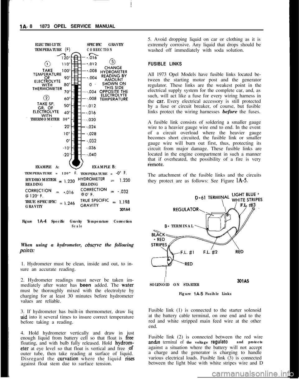
Figure
l A-4 Specific Gravity Temperature CorrectionScale
When using a hydrometer, obsqve the following
pain Is:1. Hydrometer must be clean, inside and out, to in-
sure an accurate reading.
2. Hydrometer readings must never be taken im-
mediately after water has been added. The water
must be thoroughly mixed with the electrolyte by
charging for at least 30 minutes before hydrometer
values are reliable.
3. If hydrometer has built-in thermometer, draw liq
aid into it several times to insure correct temperature
before taking a reading.
4. Hold hydrometer vertically and draw in just
enough liquid from battery cell so that float is
freefloating, and with bulb fully released. Hold bydrom-eter at eye level so that float is vertical and free
!ofouter tube, then take reading at surface of liquid.
Disregard the curvation where the liquid rises
against float stem due to surface tension.5. Avoid dropping liquid on car or clothing as it is
extremely corrosive. Any liquid that drops should be
washed off immediately with soda solution.
FUSIBLE LINKSAll 1973 Opel Models have fusible links located be-
tween the starting motor post and the generator
regulator. These links are the weakest point in the
electrical supply system for the complete car, and, as
such, will act like a fuse for every wiring harness in
the
ca.r. Every electrical accessory is still protected
by a fuse or circuit breaker, of course, but fusible
links protect the wiring harnesses before the fuses.
A fusible link consists of soldering a smaller gauge
wire to a heavier gauge wire end to end. In the event
of a circuit overload where the heavier gauge
becomes short circuited, the fusible link or smaller
gauge wire will burn out first, thus, protecting its
circuit from major damage. These fusible links are
located in the engine compartment in such a manner
that if overheated, the possibility of a fire is veryr¬e.
The attachment of the fusible links and the circuits
they protect are as follows: See Figure
l A-5.
D+61TERMIN\AL ;;!$6,,FL #3
B+ TERMINAL
I3QlA5
SOLENOID ON STARTER
Figure
t A-5 Fusible LinksFusible link (1) is connected to the starter solenoid
at the battery cable terminal, on one end and to the
red and white stripped main feed wire at the other
end.
Fusible link (2) is connected between the red wirean&s
terminal of the voltage regulateand protectsagainst a situation where the battery will not accept
a charge and the generator is charging to handle
various electrical loads. Fusible link (3) is connected
between the light blue with white stripes wire and D
Page 40 of 625
IIIGNITION SYSTEMlC- 19
11. (Startx position.) The ignition key must be
released as soon as engine starts. The switch then
returns aujomatically to the on position.
IGNITION
GOILThe ignition coil consists of a laminated non- mag-
netic iron
(core enclosed by two coils; the primary
winding and the secondary winding.
The prim+y circuit consists of the power source
(battery), the ignition switch, the ignition coil pri-
mary winding, the distributor breaker points with
ignition condenser connected in parallel, and all con-
necting
lo& tension wiring.
The secondary circuit consists of the ignition coil
secondary ‘winding, the spark plugs, all connecting
high tens@ wiring, the distributor cap and the
ro-tor.
When the’ ignition switch is turned on and the
breaker pdints are closed, current flows through the
ignition
c&l primary winding and produces a mag-
netic field wound the coil windings.
When the breaker points are separated by the revolv-
ing distributor cam, the magnetic field collapses and
induces a high voltage surge in the secondary wind-
ing,
produ;cing a spark between the spark plug elec-
trodes. ,
The ignitidn condenser which is connected in paral-
lel with the breaker points, prevents arcing between
the
separa’ted breaker contacts, and current flow
after~ the breaker points have been separated, thus
causing a kery rapid collapse of the magnetic field
around th$ Ignition coil.
/
IGNITION ‘DISTRIBUTORThe ignitidn distributor breaks the primary current,distributeslthe high voltage surges induced in the coil
secondary winding to the spark plugs according to
the engin< tiring order and sets ignition timing in
relation to. engine RPM and load.
The housi+g of the distributor contains the centrifu-
gal advance mechanism and the movable breaker
plate with’s breaker lever and contact support. The
vacuum advance mechanism is attached to the
breaker plate and mounted on the outside of the
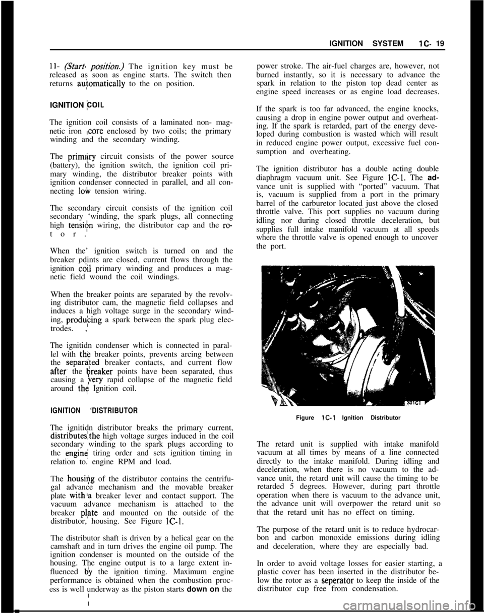
distributor, housing. See Figure lC-1.
The distributor shaft is driven by a helical gear on the
camshaft and in turn drives the engine oil pump. The
ignition condenser is mounted on the outside of the
housing. The engine output is to a large extent in-
fluenced b) the ignition timing. Maximum engine
performance is obtained when the combustion proc-
ess is well underway as the piston starts down on thepower stroke. The air-fuel charges are, however, not
burned instantly, so it is necessary to advance the
spark in relation to the piston top dead center as
engine speed increases or as engine load decreases.
If the spark is too far advanced, the engine knocks,
causing a drop in engine power output and overheat-
ing. If the spark is retarded, part of the energy deve-
loped during combustion is wasted which will result
in reduced engine power output, excessive fuel con-
sumption and overheating.
The ignition distributor has a double acting double
diaphragm vacuum unit. See Figure lC-1. The ad-
vance unit is supplied with “ported” vacuum. That
is, vacuum is supplied from a port in the primary
barrel of the carburetor located just above the closed
throttle valve. This port supplies no vacuum during
idling nor during closed throttle deceleration, but
supplies full intake manifold vacuum at all speeds
where the throttle valve is opened enough to uncover
the port.
Figure lC-1 Ignition Distributor
The retard unit is supplied with intake manifold
vacuum at all times by means of a line connected
directly to the intake manifold. During idling and
deceleration, when there is no vacuum to the ad-
vance unit, the retard unit will cause the timing to be
retarded 5 degrees. However, during part throttle
operation when there is vacuum to the advance unit,
the advance unit will overpower the retard unit so
that the retard unit has no effect on timing.
The purpose of the retard unit is to reduce hydrocar-
bon and carbon monoxide emissions during idling
and deceleration, where they are especially bad.
In order to avoid voltage losses for easier starting, a
plastic cover has been inserted in the distributor be-
low the rotor as a seperator to keep the inside of the
distributor cup free from condensation.
Page 63 of 625
1 E- 421973 OPEL SERVICE MANUAL
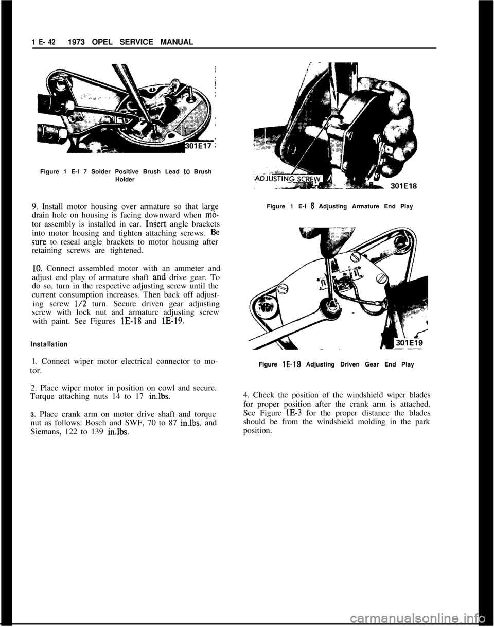
Figure 1 E-l 7 Solder Positive Brush Lead to Brush
Holder
9. Install motor housing over armature so that large
drain hole on housing is facing downward when
mb-tor assembly is installed in car.
InSert angle brackets
into motor housing and tighten attaching screws. Be
sure to reseal angle brackets to motor housing after
retaining screws are tightened.
10. Connect assembled motor with an ammeter and
adjust end play of armature shaft grid drive gear. To
do so, turn in the respective adjusting screw until the
current consumption increases. Then back off adjust-
ing screw
l/2 turn. Secure driven gear adjusting
screw with lock nut and armature adjusting screw
with paint. See Figures lE-18 and lE-19.
Installation1. Connect wiper motor electrical connector to mo-
tor.
2. Place wiper motor in position on cowl and secure.
Torque attaching nuts 14 to 17 in.lbs.
3. Place crank arm on motor drive shaft and torque
nut as follows: Bosch and SWF, 70 to 87 imlbs. and
Siemans, 122 to 139 in.lbs.Figure 1 E-l
8 Adjusting Armature End Play
Figure
lE-19 Adjusting Driven Gear End Play
4. Check the position of the windshield wiper blades
for proper position after the crank arm is attached.
See Figure lE-3 for the proper distance the blades
should be from the windshield molding in the park
position.
Page 125 of 625
I2A- 21973 OPEL SERVICE MANUAL
GENERAL INFORlVlATION
CONTENTS
SubjectPage No.
DESCRIPTION AND OPERATION: (Not Applicable)
DIAGNOSIS: (Not Applicable)
MAINTENANCE AND ADJUSTMENTS:
PaintMaintenance. . . . . . . . . . . . . . . . . . . . . . . . . . . . . . . . . . . . . . . . . . . . . . . . . . . . . . . . . . . .2A-2
ChromeMaintenance
. . . . . . . . . . . . . . . . . . . . . . . . . . . . . . . . . . . . . . . . . . . . . . . . . . . . . .2A-2
StainRemoval
. . . . . . . . . . . . . . . . . . . . . . . . . . . . . . . . . . . . . . . . . . . . . . . . . . . . . . . . . . . . . . . . . . . .2A-2
MAJOR REPAIR: (Not Applicable)
SPECIFICATIONS:
Bolt
TorqueSpecifications. . . . . . . . . . . . . . . . . . . . . . . . . . . . . . . . . . . . . . . . . . . . . .2A-4
Special Body Tools
. . . . , . . . . . . . . . . . . . . . . . . . . . . . . . . . . . . . . . . . . . . . . . . . . . . . . . . . . . . .2A-5
MAINTENANCE AND ADJUSTMENTSPAINT MAINTENANCE
To remove heavy concentrations of road dirt and
grime, it is recommended that the car be washed
using an automotive shampoo or mild soap, and cold
to lukewarm water. Use of harsh soaps or detergents
is not advised. In areas where salt is used on the
roads during the winter months, more frequentwashing is recommended.
Use of cleaners and polishes are required if no high
luster is obtainable by waxing. To protect the paint
finish, sparingly apply several coats of wax. Each
coat should be thoroughly rubbed to remove any
surplus wax.
Once the car is properly waxed, road dirt may easily
be removed by use of cold to lukewarm water and a
sponge. Dry by use of a chamois.
CHROME MAINTENANCE
Chrome parts should be washed with water and a
mild detergent. If rust or salt corrosion should ap-
pear, they may be removed with Buick Rust Eraser
or equivalent. Do not use scouring powders or stiff
brushes.STAIN REMOVAL
Before attempting to remove spots or stains from
upholstery fabrics, determine as accurately as possi-
ble: (1) Nature and age of the spot or stain. (2) The
affect of stain removing agents on the color, struc-
ture and general appearance of the fabric.
For best results, stains should be removed from
upholstery as soon as possible after they have been
made. If they are allowed to stand for some time,
they often become set, and removal becomes more
diffxult and frequently impossible.
There are three basic types of acceptable’ cleaners
available to car owners: (1) Volatile cleaners, (2) Syn-
thetic detergents, (3) Neutral soap (non-alkaline).
The volatile cleaners are recommended since they
have great solvent powers for grease, oils and general
road grime. Synthetic detergents generally loosen
stains satisfactorily, however, the use of improper
type detergents (containing bleach) involves risk of
damage to the color or finish of fabrics.
Precautions For Cleaning FabricsDo not use laundry soap or detergents containing
bleaches. The use of these agents tends to weaken
fabric and to change its color. Do
not use too much
cleaning fluid. Some interior trim assemblies are pad-
Page 149 of 625
2F-261973 OPEL SERVICE MANUALMAINTENANCE AND ADJUSTMENTSADJUSTING HEIGHT OF SUN ROOF PANEL
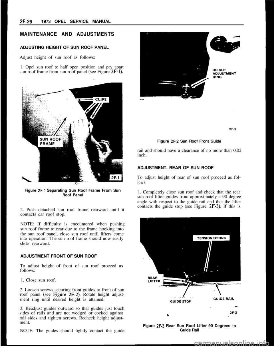
Adjust height of sun roof as follows:
1. Opel sun roof to half open position and pry apart
sun roof frame from sun roof panel (see Figure
2F-1).Figure
ZF-1 Separating Sun Roof Frame From SunRoof Panel2. Push detached sun roof frame rearward until it
contacts car roof stop.
NOTE: If difficulty is encountered when pushing
sun roof frame to rear due to the frame hooking into
the sun roof panel, close sun roof until lifters come
into operation. The sun roof frame should now easily
slide rearward.
ADJUSTMENT FRONT OF SUN ROOF
To adjust height of front of sun roof proceed as
follows:
1. Close sun roof.
2. Loosen screws securing front guides to front of sun
roof panel (see Figure
2F-2). Rotate height adjust-
ment ring until desired height is attained.
3. Readjust guides outward so that guides just touch
sides of rails and are not wedged or cocked against
rail sides and tighten screws. Recheck height adjust-
ment.
NOTE: The guides should lightly contact the guideFigure
ZF-2 Sun Roof Front Guide
rail and should have a clearance of no more than 0.02
inch.
ADJUSTMENT. REAR OF SUN ROOF
To adjust height of rear of sun roof proceed as fol-
lows:1. Completely close sun roof and check that the rear
sun roof lifter guides from approximately a 90 degree
angle with respect to the guide rail and that the lifter
contacts the guide stop (see Figure
2F-3). If this is
Figure
2F-3 Rear Sun Roof Lifter 90 Degrees toGuide Rail
Page 151 of 625
2F-281973 OPEL SERVICE MANUAL
guides to height adjustment rings, loosen second
screw (see Figure 2F-6), and swing guides away from
guide rail.
NOTE: When swinging front guides inboard, be
careful not to change position of height adjustment
rings. It is suggested that the position of the height
adjustment rings be marked with a pencil prior to
loosening of front guide attaching screws.
5. Retighten remaining screw holding front guide in
position to prevent height adjustment rings from
turning.
6. Turn lifter guide tension springs 90 degrees in-
board and pull lifters out of sun roof panel brackets
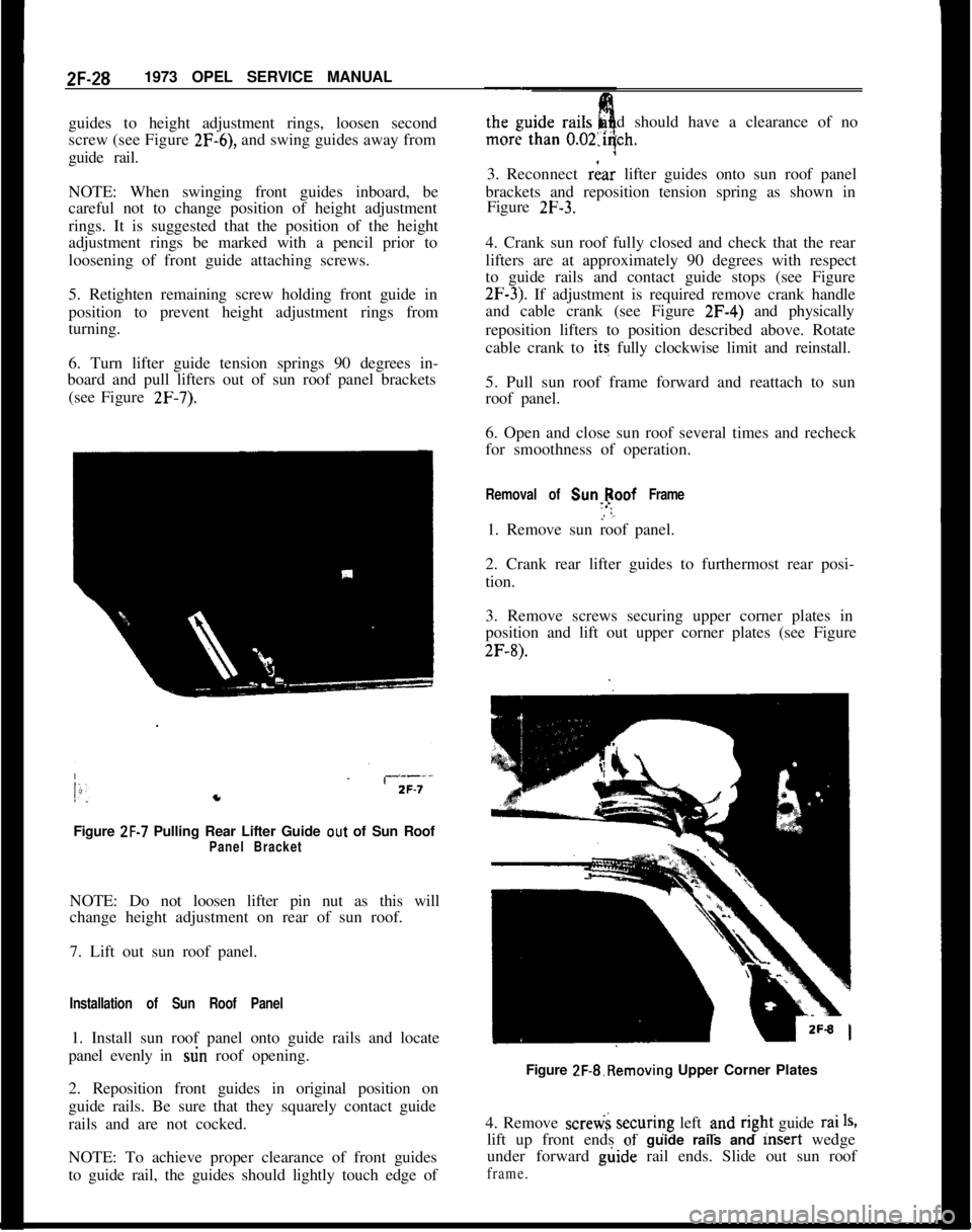
(see Figure
2F-7).Figure
ZF-7 Pulling Rear Lifter Guide out of Sun RoofPanel BracketNOTE: Do not loosen lifter pin nut as this will
change height adjustment on rear of sun roof.
7. Lift out sun roof panel.
Installation of Sun Roof Panel1. Install sun roof panel onto guide rails and locate
panel evenly in stin roof opening.
2. Reposition front guides in original position on
guide rails. Be sure that they squarely contact guide
rails and are not cocked.
NOTE: To achieve proper clearance of front guides
to guide rail, the guides should lightly touch edge ofdshould have a clearance of no
3. Reconnect
riar lifter guides onto sun roof panel
brackets and reposition tension spring as shown in
Figure
2F-3.4. Crank sun roof fully closed and check that the rear
lifters are at approximately 90 degrees with respect
to guide rails and contact guide stops (see Figure
2F-3). If adjustment is required remove crank handle
and cable crank (see Figure 2F-4) and physically
reposition lifters to position described above. Rotate
cable crank to its fully clockwise limit and reinstall.
5. Pull sun roof frame forward and reattach to sun
roof panel.
6. Open and close sun roof several times and recheck
for smoothness of operation.
Removal of Sunlpoof Frame1. Remove sun roof panel.
2. Crank rear lifter guides to furthermost rear posi-
tion.
3. Remove screws securing upper corner plates in
position and lift out upper corner plates (see Figure
2F-8).Figure 2F-&Removing Upper Corner Plates
4. Remove scretii securing left und
r@t guide rai1%lift up front ends
of- guide rails and msert wedge
under forward g&de rail ends. Slide out sun roof
frame.
Page 153 of 625
2F-301973 OPEL SERVICE MANUAL
3. Unscrew and remove upper and lower corner
plates (see Figure 2F-8).4. Unscrew and remove left and right upper cable
shields ans pull cable ends out of cable box.
5. Pull cable and rear lifter guides out of leftand
right guide rails.
Installation of Rear Guides and Cable1. Check both cables for wear or damage. If eigher
cable is defective, replace both cables.
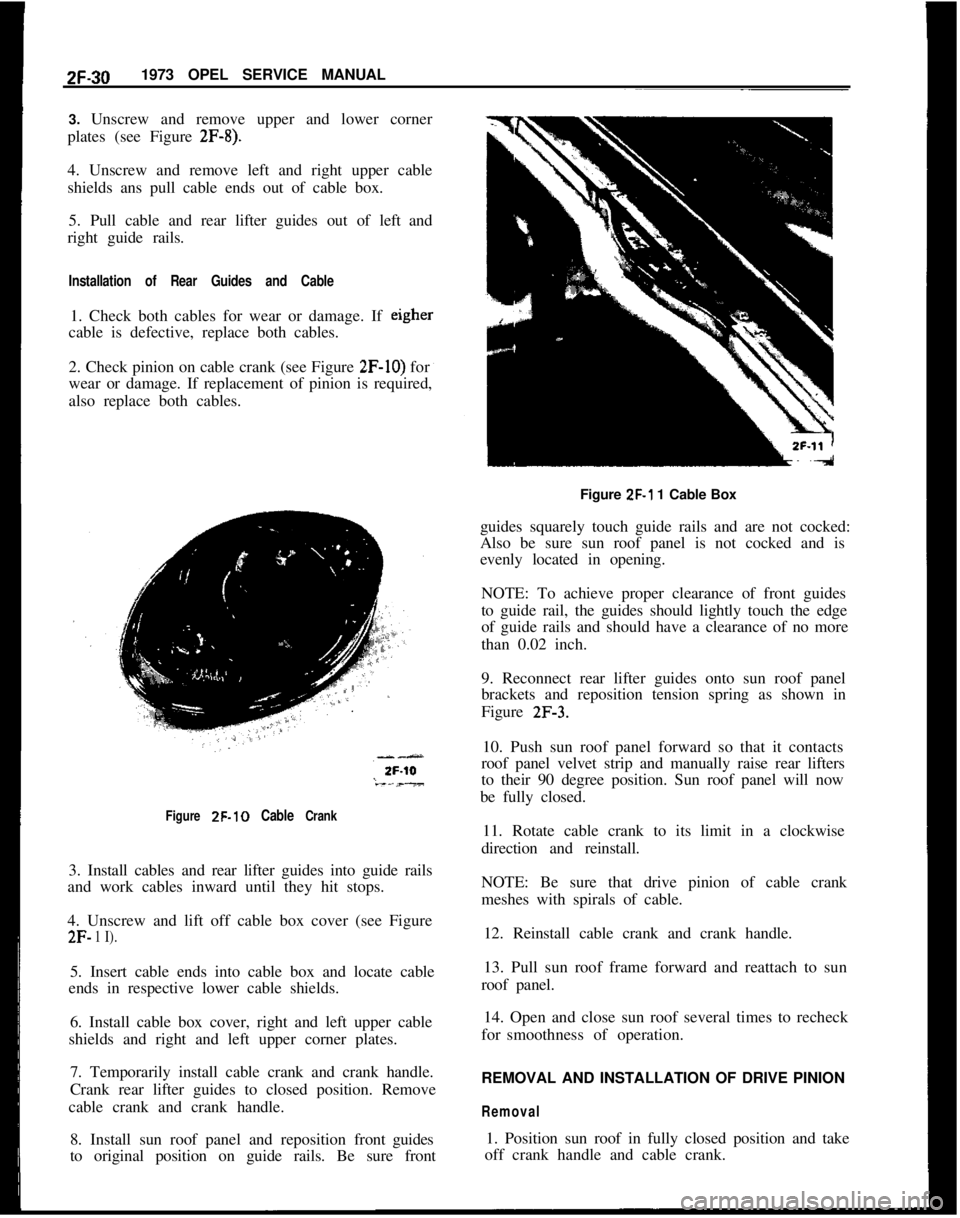
2. Check pinion on cable crank (see Figure
2F-IO) for
wear or damage. If replacement of pinion is required,
also replace both cables.
Figure ZF-10 Cable Crank3. Install cables and rear lifter guides into guide rails
and work cables inward until they hit stops.
4. Unscrew and lift off cable box cover (see Figure
2F- 1 I).5. Insert cable ends into cable box and locate cable
ends in respective lower cable shields.
6. Install cable box cover, right and left upper cable
shields and right and left upper corner plates.
7. Temporarily install cable crank and crank handle.
Crank rear lifter guides to closed position. Remove
cable crank and crank handle.
8. Install sun roof panel and reposition frontguides
to original position on guide rails. Be sure frontFigure
ZF-1 1 Cable Box
guides squarely touch guide rails and are not cocked:
Also be sure sun roof panel is not cocked and is
evenly located in opening.
NOTE: To achieve proper clearance of front guides
to guide rail, the guides should lightly touch the edge
of guide rails and should have a clearance of no more
than 0.02 inch.
9. Reconnect rear lifter guides onto sun roof panel
brackets and reposition tension spring as shown in
Figure
2F-3.10. Push sun roof panel forward so that it contacts
roof panel velvet strip and manually raise rear lifters
to their 90 degree position. Sun roof panel will now
be fully closed.
11. Rotate cable crank to its limit in a clockwise
direction and reinstall.
NOTE: Be sure that drive pinion of cable crank
meshes with spirals of cable.
12. Reinstall cable crank and crank handle.
13. Pull sun roof frame forward and reattach to sun
roof panel.
14. Open and close sun roof several times to recheck
forsmoothness of operation.
REMOVAL AND INSTALLATION OF DRIVE PINION
Removal1. Position sun roof in fully closed position and take
off crank handle and cable crank.