radio OPEL GT-R 1973 Service Manual
[x] Cancel search | Manufacturer: OPEL, Model Year: 1973, Model line: GT-R, Model: OPEL GT-R 1973Pages: 625, PDF Size: 17.22 MB
Page 5 of 625
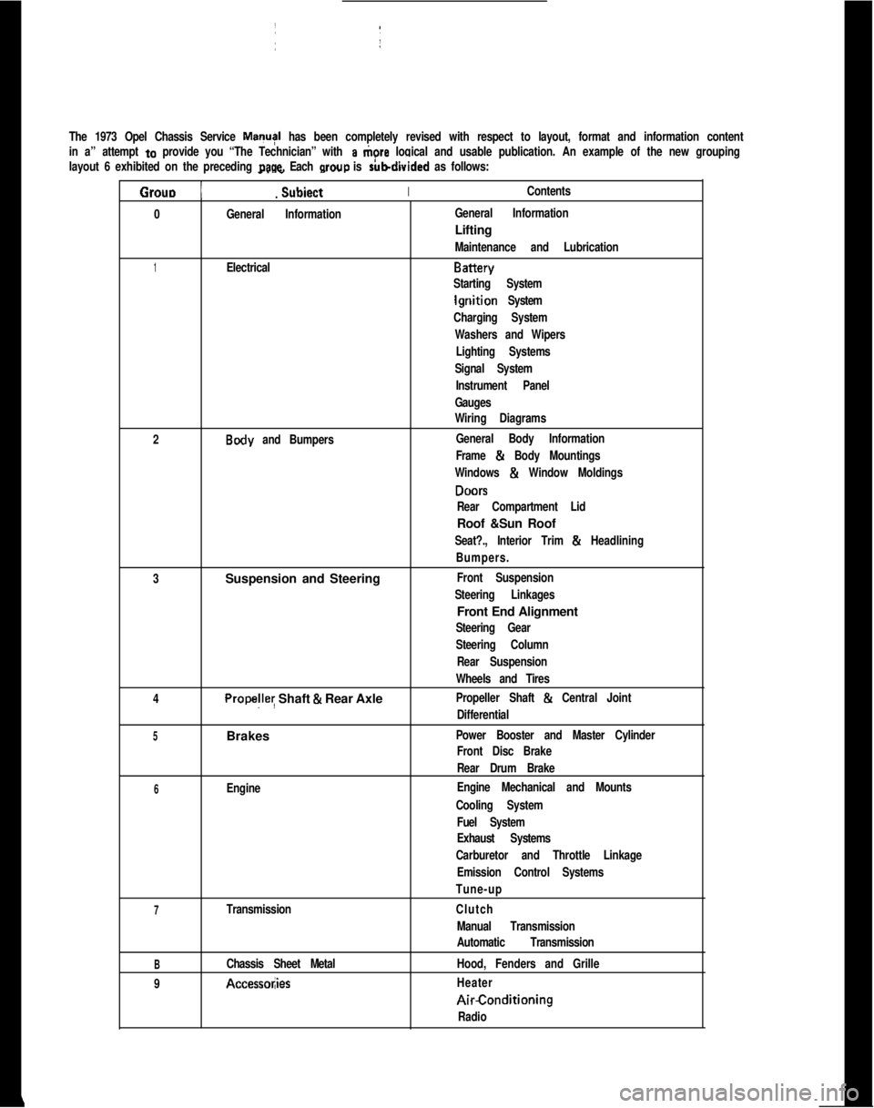
The 1973 Opel Chassis Service MayI has been completely revised with respect to layout, format and information content
in a” attempt
to provide you “The Technician” with a tiore logical and usable publication. An example of the new grouping
layout 6 exhibited on the preceding
page. Each wow is rubdivided as follows:
Grouo 1
_. _
Subiect IIContents.
0
General InformationIGeneral InformationLifting
Maintenance and Lubrication
1ElectricalBattery
Starting System
lgriition System
Charging System
Washers and Wipers
Lighting Systems
Signal SystemI
Instrument Panel
Gauges
Wiring Diagrams
2
Body and Bumpers:General Body InformationI
Frame & Body Mountings
Windows
& Window Moldings
DONS
Rear Compartment LidRoof &Sun Roof
Seat?., Interior Trim & Headlining
Bumpers.
3Suspension and Steering
Front Suspension
Steering Linkages1Front End Alignment
Steering Gear
Steering Column
Rear Suspension
Wheels and Tires
4
Propelley Shaft & Rear AxlePropeller Shaft & Central Joint
Differential
5Brakes ~Power Booster and Master Cylinder
Front Disc BrakeI
Rear Drum Brake
6EngineEngine Mechanical and Mounts
Cooling System
Fuel System
Exhaust Systems
Carburetor and Throttle Linkage
Emission Control Systems
Tune-up
7TransmissionClutch
Manual Transmission
Automatic Transmission
BChassis Sheet MetalHood, Fenders and Grille
9
Accessol;iesHeaterAirConditioning
Radio
Page 42 of 625
IGNITION SYSTEMlC-214. Rota&distributor counterclockwise slightly until
contact pbints just start to open. This must be done
very carefully or engine will not start.
5. Install distributor cap. Make sure spark plug wires
are correctly installed in distributor cap, through clip
and on spark plugs.
Finish TimingIContact boint gap
(.016” at widest gap) or dwell 50
degrees plus or minus 3 degrees should always be
checked before adjusting ignition timing.
1. Connekt timing light to No. 1 spark plug.
2. Disconnect and plug vacuum advance unit and
retard u$it hoses.
3. Connect a tachometer from distributor side of coil
to
groun$l.4. Start dngine. Set idle speed to 900 RPM.
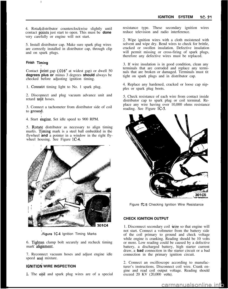
5. Rotate distributor as necessary to align timing
marks. T;ming mark is a steel ball embedded in the
flywheel and a pointer in a window in the right fly-
wheel housing. See Figure lC-4.:Figure lC-4 Ignition Timing Marks
6.
Tightq clamp bolt securely and recheck timing
mark ahgnment.
7. Reconnect vacuum hoses and adjust engine idle
speed
an: mixture.
IGNlTlOFj WIRE INSPECTION
1. The c$il and spark plug wires are of a specialresistance type. These secondary ignition wires
reduce television and radio interference.
2. Wipe ignition wires with a cloth moistened with
solvent and wipe dry. Bend wires to check for brittle,
cracked or swollen insulation. Defective insulation
will permit missing or cross-firing of spark plugs,
therefore any defective wires must be replaced.
3. If wire insulation is in good condition, clean any
terminals that are corroded and replace any termi-
nals that are broken or damaged. Terminals must tit
tight on spark plugs and in distributor cap.
4. Replace any hardened, cracked or loose cap nip-
ples or spark plug boots.
5. Check resistance of each wire from contact inside
distributor cap to spark plug or coil terminal. Re-
place any wire having over 10,000 ohms resistance
reading. See Figure lC-5.
Figure fC-5 Checking Ignition Wire Resistance
CHECK IGNITION OUTPUT
1. Disconnect secondary coil ivire so that engine will
not start. Connect a voltmeter from the battery side
of the coil primary to ground and check voltage
while engine is cranking. Reading should be 10 volts
or more. Low reading could be caused by a defective
battery, a discharged battery, high starter current
draw, a bad connection in the starter circuit or a bad
connection in the primary ignition circuit.
2. Connect an oscilloscope according to manufac-
turer’s instructions. Disconnect coil wire. Crank en-
gine and read coil output voltage. Reading should
exceed 20 KV (20,000 volts).
Page 77 of 625
:lG- 56 1973 OPEL SERVICE MANUAL
I
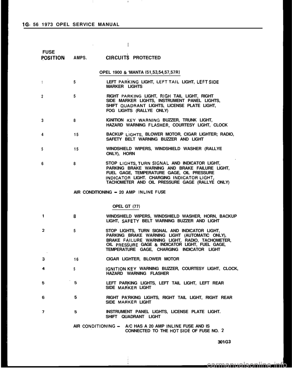
FUSEqOSlTlON
1
2
3
4
5
6AMPS.
5
5
8
15
15
8ClRClJlT$ PROTECTED
OPEL 1900
& ‘MANTA (51,53,54,57,57R)
LEFT PARkING LIGHT,
LEFTTAIL LIGHT, LEFTSIDE
MARKER LIGHTS
RIGHT PApKING LIGHT, RIGH TAIL LIGHT, RIGHT
SIDE MARKER LIGHTS, INSTRUMENT PANEL LIGHTS,
SHIFT GUADRANT LIGHTS, LICENSE PLATE LIGHT,
FOG LIGHTS (RALLYE ONLY)
IGNITION IKEY
WARNIN BUZZER, TRUNK LIGHT,
HAZARD WARNING FLA,SHER, COURTESY LIGHT, CLOCK
BACKUP L’IGHTS, BLOWER MOTOR, CIGAR LIGHTER; RADIO,
SAFETY BELT WARNING BUZZER AND LIGHT
WINDSHIELD WIPERS, WINDSHIELD WASHER (RALLYE
ONLY), HORN
STOP LIGtiTS,TURN
SlGsNAL AND INDICATOR LIGHT,
PARKING BRAKE WARNING AND BRAKE FAILURE LIGHT,
FUEL GAGE, TEMPERATURE GAGE, OIL PRESSUREINDICATGR LIGHT. CHARGING INDICATOR~LIGHT,
TACHOMETER AND OIL PRESSURE GAGE (RALLYE ONLY)
AIR CONDITIONING
- 20 AMP INLINE F:USE
8
5
16
5OPEL GT
(77)WINDSHIELD WIPERS, WINDSHIELD WASHER, HORN, BACKUP
LIGHT, SP;FETY BELT WARNING BUZZER AND LIGHT
STOP LIGHTS, TURN SIGNAL AND INDICATOR LIGHT,
PARKING BRAKE WARNING LIGHT (AUTOMATIC ONLY),
BRAKE FAILURE WARNING LIGHT, RADIO, TACHOMETER,
OIL PRESiURE GAGE
& INDICATOR LIGHT, FUEL GAGE,
TEMPERATURE GAGE, CHARGING INDICATOR LIGHT
CIGAR LIGHTER, BLOWER MOTORIGNITION~KEY WARNING BUZZER, COURTESY LIGHT, CLOCK,
HAZARD WARNING FLASHER
LEFT PARKING LIGHTS, LEFT TAIL LIGHT, LEFT REAR
SIDE MAdKER LIGHT
RIGHT PA’RKING LIGHTS, RIGHT TAIL LIGHT, RIGHT REAR
SIDE MAdKER LIGHT
INSTRUMENT PANEL LIGHTS, LICENSE PLATE LIGHT.
SHIFT QUADRANT LIGHT
AIR CON,DlTlONlNG
-A/C HAS A 20 AMP INLINE FUSE AND IS
CONNECTED TO THE HOTSIDE OF FUSE NO. 23OlG3
Page 83 of 625

1 H- 62 1973 OPEL SERVICE, MANUAL
4. Remove flasher unit. See Figure IH-12.
5. Position steering so that wheels are straight ahead.
6. Pull off heads of both tear bolts by first drilling a3/16 inch pilot hole and then using a stud extractor
to remove tear bolts. See Figure lH-13.
Figure 1 H-10 Removing Right Aicess Cover andSWW3. Remove left access cover and f”rnove screw. See
Figure lH-11.
Figure 1 H-l 3 Steering Column Attaching Bolts
7. Disconnect ignition (white) and directional signal
(black) wire set plugs.
8. Support steering column assembly and remove
both hex head bolts. See Figure lH-13.
9. Drop steering column assembly to floor.
10. Disconnect speedometer cable.
11. Remove six (6) screws on instrument cluster. See
Figure
lH- 14.
Figure lli-1 1 Removing Left Access Cover and
SC&Figure lH-14 Instrument Cluster Screws
12. Pull back on instrument cluster from top to
remove. See Figure lH-15.
Figure l H-12 Flasher Unit Installed13. Disconnect wires on back of radio. See FigurelH-16.
Page 84 of 625
I
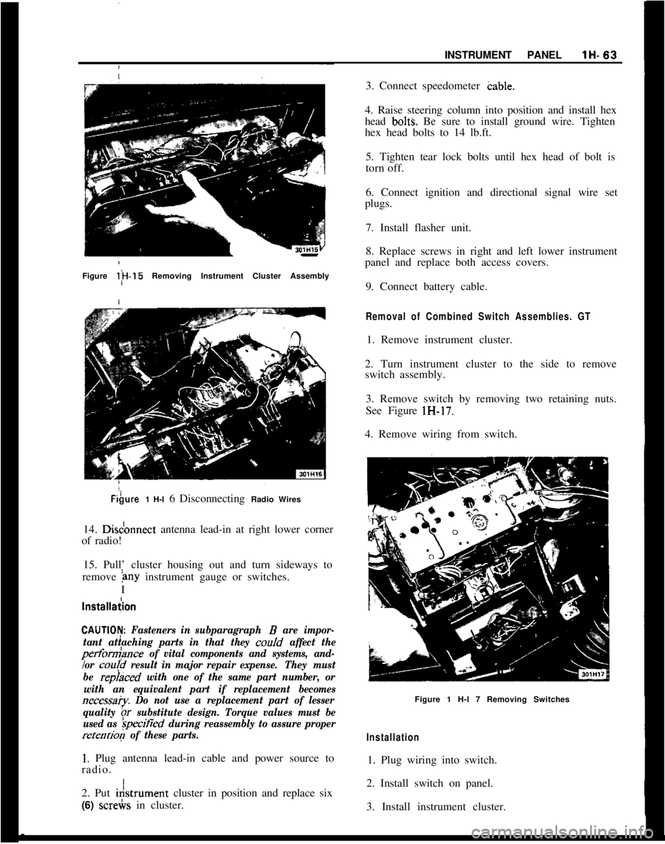
,INSTRUMENT PANELlH-63Figure l;H-15 Removing Instrument Cluster AssemblyFibure1 H-l 6 Disconnecting Radio Wires
14. Disdonnect antenna lead-in at right lower corner
of radio!
15. Pull’ cluster housing out and turn sideways to
remove
&~y instrument gauge or switches.
I
lnstallaiion
CAUTlOI$ Fasteners in subparagraph B are impor-
tant attaching parts in that they coo/d
affect the
perform>nce of vital components and systems, and-
/or
cou!d result in major repair expense.They must
be
repraced with one of the same part number, or
with an equivalent part if replacement becomes
necessa?y. Do not use a replacement part of lesser
quality
br substitute design. Torque values must be
used as
&ified during reassembly to assure proper
retention of these parts.
1. Plug antenna lead-in cable and power source to
radio. I
2. Put i&trument cluster in position and replace six
(6) screbs in cluster.3. Connect speedometer cable.
4. Raise steering column into position and install hex
head
bolt% Be sure to install ground wire. Tighten
hex head bolts to 14 lb.ft.
5. Tighten tear lock bolts until hex head of bolt is
torn off.
6. Connect ignition and directional signal wire set
plugs.
7. Install flasher unit.
8. Replace screws in right and left lower instrument
panel and replace both access covers.
9. Connect battery cable.
Removal of Combined Switch Assemblies. GT1. Remove instrument cluster.
2. Turn instrument cluster to the side to remove
switch assembly.
3. Remove switch by removing two retaining nuts.
See Figure lH-17.
4. Remove wiring from switch.
Figure 1 H-l 7 Removing Switches
Installation1. Plug wiring into switch.
2. Install switch on panel.
3. Install instrument cluster.
Page 90 of 625

I
IGAUGES1 I- 69
I
I
3. Replace instrument housing.InstallationFiemoving~Temperature Indicator or Fuel Gauge
1. Remov+ instrument cluster housing.
2. Remov; six screws and remove both instrument
cluster
le+ See Figure 11-2.3. Pull v&age stabilizer off printed circuit and
remove fohr instrument attaching screws, as shown
in Figure
111-5.Figure
11-5 Removing Four Instrument Attaching\SCWWS
4. Take temperature or fuel gauge out of clusterlnstallatidn
1. Install itemperature or fuel gauge in cluster.
2. Replack voltage stabilizer on back of printed cir-
cuit. I
3. Replack both instrument cluster lens.
I
4. Install /instrument cluster housing.
I
IRemwind Rallye Gauges
1. Removt glove compartment.
2. Remo?e radio, if equipped.
3.
Remoje screws holding instrument carrier frominstrumejf
pane!.4. Disconpect wres from instrument gauge.
5.
Removal attaching nuts from gauge and remove.I1. Replace gauge with attaching nuts on panel.
2. Hook up wires to gauges.
3. With holding screws, attach gauge cluster to in-
strument panel.
4. Replace radio.
5. Replace glove compartment.
Removal of Temperature Sending Unit
1. Drain and collect coolant.
To drain radiator, remove end of lower radiator hose
that is connected to radiator.
2. Remove wire from temperature sending unit.
3. Unscrew temperature sending unit from thermo-
stat housing. See Figure
11-6.Figure
11-S -Temperature Sending Unitlnstalletian
1. Screw temperature sending unit into thermostat
housing after sealing unit with non-hardening per-matex.
2. Install wire on sending unit.
3. Replace coolant.
Page 510 of 625
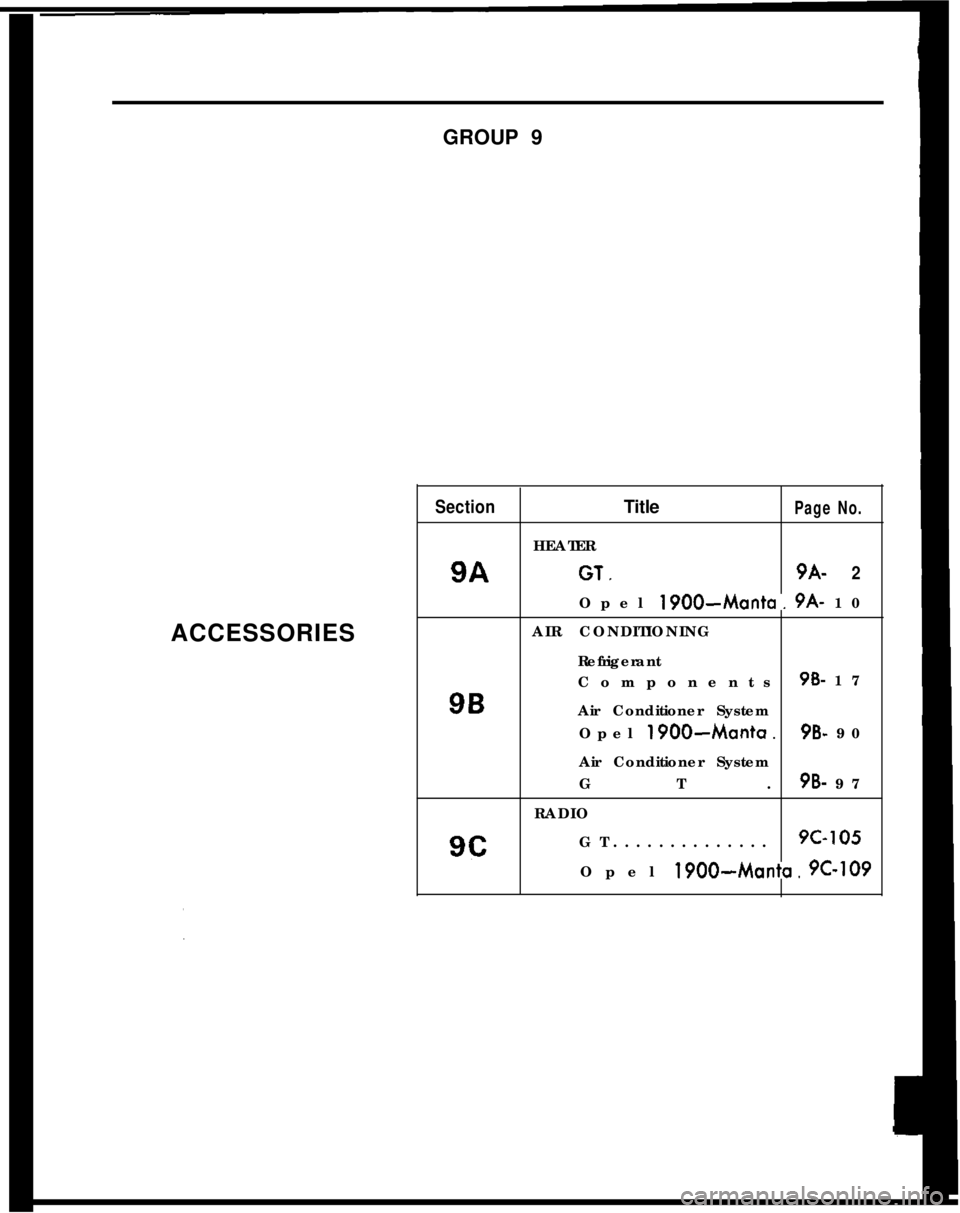
GROUP 9
ACCESSORIESSectionTitlePage No.HEATER
9AGT,9A-2Opel
1900-Manta. 9A- 10
AIR CONDITIONING
Refrigerant
Components9B- 179B
Air Conditioner System
Opel
1900~Manta.9B- 90
Air Conditioner System
GT.
OB- 97
RADIO
9cGT..............9c-105Opel
1900~Manta. PC-109
Page 521 of 625

9A-i2 1973 OPEL SERVICE MANUAL
Check that air doors and water temperature control
valve are operating properly.
Check for plugged heater core-backflush heater core
as necessary.TROUBLEInadequate defrosting action.
CAUSE AND CORRECTIONExamine heater-defroster door for proper operation.
Adjust bowden cable so that door is fully closed in
FULL DEFROST position.
Check that air hoses connecting to defroster outlets
are secure.
Check for air leaks around edges of heater air dis-
tributor housing. Seal leaks, as necessary, with bodysea@. Check for body air leaks and seal, as neces-
sary, with body sealer.
TROUBLEBlower inoperative.
CAUSE AND CORRECTIONCheck blower fuse. Replace, if necessary, fuse posi-
tion 4
- amperage 15.
Check wiring for open circuit. Correct, as required.
Inspect for defective component, (i.e., blower switch
or blower motor)
- replace or repair as necessary.
MAINTENANCE AND ADJUSTMENTS
CONTROL CABLE ADJUSTMENTAdjustment of control cables is accomplished by po-
sitioning of the jacket or sheath of the control cable,
as held by the clamps on the control assembly and
heater case or by loosening screws and slidingbowden wire to obtain desired door or water valve
position.
MAJOR REPAIR
REMOVING AND INSTALLING HEATER HOUSING
Removal1. Unscrew hood lock together with ground wire(ground wire only on vehicles with radio interference
suppression). See Figure 9A-33.
Figure 9A-33 Hood Lock Attachments
2. Unscrew heater housing cover.
3. Pull hose of windshield washer system off jet and
take jet out of housing cover.
4. Unscrew bowden control wire from heater valve.
5. Unscrew heater housing from dash panel and pull
it off carefully. See Figure 9A-34.
Figure 9A-34 Heater Housing Attachments
6. Remove water hoses from heater core and pull
heater core out of heater housing. See Figure
9A-35.
Page 522 of 625

Figure SA-35 Heater Core
Installation
1. Apply sealing compound between heater housing
and dash panel.
2. Install heater core into heater housing and attach
water hoses. See Figure 9A-35.
3. Instaii heater housing to dash panel. S,ee Figure9A-44.
4. Install bowden control wire to heater valve.
5. Install windshield washer jet into housing cover
and attach hose.
6. Install heater housing cover, and seal with a seal-
ing compound.
7. Install hood lock, together with
grc’und wire
(ground wire only on vehicles with radio interference
suppression).
REMOVING AND INSTALLING
DEFROSTE+lOUTLETS
Removal
1. Pull out heater switch lever. See Figure 9A- 36.
2. Remove instrument cover.
3. Unscrew bowden control wires from heater valve
and air distributor housing and pull out heater con-
trols.
4. Remove glove compartment.
HEiATER SYSTEM - OPEL 1900 - MANTA9A. 13Figure SA-36 Removing Heater Switch Lever
5. Remove radio.
6. On right side, viewed in driving direction, remove
air distributor housing attaching screws. See Figure9A-37
Figure SA-37 Air Distributor Housing Attaching
SCWWS7. On left side, viewed in driving direction, remove
upper attaching screw through opening for heater
control housing and lower attaching screw below
instrument panel. See Figure 9A-38.
8. Pull air distributor housing off dash panel
Page 523 of 625

9A-14 1973 OPEL SERVICE MANUAL
upper attaching screw through opening for heater
control housing and lower attaching screw below
instrument panel. See Figure 9A.-38.5. On right side, viewed in driving direction, install
air distributor housing attaching screws. See Figure9A-37.
6. Install radio.
7. Install glove compartment.
8. Install bowden control wires to heater valve and
air distributor housing.
9. Install instrument cover.
10. Install heater switch lever.
Figure 9A-38 Upper Attaching Screw
9. Pull defroster outlets downwards and remove out-
lets through glove compartment opening. See Figure9A-39.
REMOVAL AND INSTALLATION OF HEATER
CONTROL HOUSING
Removal1. Remove instrument panel cover
- refer to operat-
ion,
IRemoving and Installing Instrument Housing.
2. Remove two sheet metal screws for control hous-
ing attachment. See Figure 9A-40.
Figure 9A-39 Removing Defroster Jets
Installation
1. Apply sealing compound between air distributor
housing and dash panel.
2. Install defroster outlets, securing with two (2)
clips at the instrument panel. See Figure 9A-39.
3. Install air distributor housing to dash panel,
4. On left side, viewed in driving direction, installFigure 9A-40 Control Housing Attaching Screws
3. In engine compartment, detach bowden control
wire from heater valve. See Figure 9A-41.
4. Detach bowden control wire from air distribution
flap. See Figure 9A-42.
5. Pull wires off blower switch. See Figure 9A- 43.