torque OPEL GT-R 1973 Service Manual
[x] Cancel search | Manufacturer: OPEL, Model Year: 1973, Model line: GT-R, Model: OPEL GT-R 1973Pages: 625, PDF Size: 17.22 MB
Page 20 of 625
LUBRICATION AND MAINTENANCE OC-11
Throttle Linkage
Check for damaged or missing parts, interference or
binding. Any deficiencies should be corrected with-
out delay.
Headlights
Check for proper aim. Correct as necessary. More
frequent checks should be made if oncoming motor-
ists signal when you are already using your low
beams, or if illumination of the area ‘ahead seems
inadequate.
Underbody
In geographic areas using a heavy concentration of
road salt or other corrosive materials for snow re-
moval or road dust control, flush and inspect the
complete under side of the car at least once each
year, preferably after a winter’s exposure. Particular
attention should be given to cleaning out underbody
members where dirt and other foreign materials may
have collected.
EMISSION CONTROL MAINTENANCE
Thermostatically Controlled Air Cleaner
Inspect installation to make certain that all hoses and
ducts are connected and correctly installed. Also,
check valve for proper operation.
Carburetor Choke
Check choke mechanism for free operation. A bind-
ing condition may have developed from petroleum
gum formation on the choke shaft or from overtight-
ening of air cleaner clamp. Also check electric choke
terminal connections and fuse.
Timing, Dwell and Distributor
Adjust timing and dwell accurately as outlined under
Tune-Up in Group 6 at the first 4 months or 6,ooOmiles of operation, then at 12 month or
12,OQO mile
intervals. Adjustments must be made with test equip-
ment known to be accurate.
Replace distributor points every 12 months or 12,000
miles and carefully clean and inspect the complete
distributor cap to prevent misfiring and deteriora-
tion.
Carburetor and Idle
SpeedTorque carburetor attaching bolts and/or nuts to 12
ft.lbs. to compensate for compression of gasket atiirst 4 months or 6,000 miles of vehicle operation.Adjust idle speed to specifications with known accu-
rate equipment.
Proper functioning of the carburetor is particularly
essential to control of emissions. Correct mixtures
for emission compliance and idle quality have been
preset by Opel. Plastic idle mixture limiters have
been installed on the idle mixture screw, idle air
screw, and throttle stop screw to preclude unauthor-
ized adjustment. The plastic caps on the idle mixture
screw and the idle adjustment screw must be
removed to perform an idle speed adjustment. The
plastic cap on the throttle stop screw is not to be
removed unless some major carburetor repair or re-
placement which affects the throttle stop screw ad-
justment has been necessary.
Carburetor Fuel Inlet Filter
Replace filter at 12 month or
12,OCO mile intervals
or more often if clogged.
Spark Plugs
Replace at
6,ooO mile intervals when operating with
leaded fuels or at 12,000 mile intervals when using
unleaded fuels. Use of leaded fuels results in lead
deposits on spark plugs and can cause misfiring at
mileages less than
12,OilO miles. Where misfiring oc-
curs prior to
6,ooO miles, spark plugs in good condi-
tion can often be cleaned, tested and reinstalled in an
engine with acceptable results.
Spark Plug Wires
Inspect spark plug wires for evidence of checking or
cracking of exterior insulation and tight fit in the
distributor cap and at the spark plugs. Exterior of
wires should be cleaned, any evidence of corrosion
on ends removed and wire replace if deteriorated.
Positive Crankcase Ventilation System
The PCV metered orifice should be cleaned at 12,000
mile intervals under normal use, and at 6,000 mile
intervals when the vehicle is used under the follow-
ing conditions: driving in dusty conditions, extensive
idling, trailer pulling and short trip operation at
freezing temperatures (engine not thoroughly
warmed-up).
Evaporation Control System
Check all fuel and vapor lines and hoses for proper
connections and correct routing as well as condition.
Remove canister and check for cracks or damage.
Replace damaged or deteriorated parts as necessary.
Replace filter in open end of canister at 24month/24,000 mile intervals.
Page 44 of 625
IGNITION SYSTEMlC- 23
9. Install:spark plugs using a 13/16 deep socket, an
extension and a torque wrench. Tighten to 22-29Ib.ft. 1
MAJOR REPAIRDlSTRlBtiTOR OVERHAULDistributbr Removal
1. Remove fuel pump. This is necessary because the
fuel
punp will block the distributor drive gear,
thereby preventing removal of the distributor. See
Figure lC-6.
2. Set No; 1 cylinder at firing point by turning engine
INOTCH IN STATIONARY& -.until cutout in distributor shaft (or rotor tip) points
to notch in distributor housing. See Figure
lC- 7.
3. Ball imbedded in flywheel should be approxi-
mately aligned with pointer in housing. See FigurelC-4.
4. Remove distributor hold-down clamp and remove
distributor. See Figure lC-8. Cover bore in timing
case to prevent foreign material from dropping into
engine. To make reinstallation of distributor easy, do
not rotate crankshaft or oil pump.
Disassembly
1. Remove distributor cap retaining spring clips, and
vacuum control units. See Figure lC-9.
Figure lC-9 Removing Retaining Clips
Figury lC-7 Aligning Shaft Cutout With Notch
Figure lC-8 Removing DistributorFigure lC-10 Removing Retaining Ring
Page 47 of 625
lC- 261973 OPEL SERVICE MANUAL /
SPECIFICATIONSIGNITION COIL
Ignition Coil Number
.,.:.................................................................................................K12 V
Ignition Coil Current Draw, Amperes at 12.5 Volts
EngineStopped
...........:.........................._............................................................................3.8Engine Idling
....................................................................................................................2.3
DISTRIBUTORDistributor TypeNumber:
..................................................................................................JFU4
Total Advance (Centrifugal and Vacuum), Engine Degrees at 3600 R.P.M.
EngineRPM
..................................................................................................................29-37Centrifugal Advance, Engine Degrees and RPM
StartAdvance,atRPM
........................................................................................lOOO-1200MediumAdvance,DegreesatRPM
..............................................................7.5-15at1400Maximum Advance, Dkgrees at RPM
..........................................................28-32 at 3600
Vacuum Advance, Engine Degrees and
In. of Vacuum
Start Advance, at In. of Vacuum
................................................................-5 at 2.9-4.1 In.
Maximum Advance, Degrees at In. of Vacuum
........................................l-5 at 4.5-5.0 In.
VacuumRetard,EngineDegreesatClosedThrottle
............................................................-5CondenserCapacityinMicroFarads
...............................................................................15-.20Breaker Spring Tension in Ounces
..............................................................................14 to 19
Breaker Point Gap in Inches
..............................................................................................,016Dwell angle in Engine Degrees
....................................................................................50 + 3
Firing Order
....................................................................................................................l-32-2
SparkPlug or CoilCable,Max.Resistancti in Ohms
..................................................10,ooO
SPARK PLUGSMake and Model
-Production................I....................................................................AC42FS
Make and Model
- Replacement...................................................................................AC42FS
Ifcarbonfouling
occurs,use.....................................................................................AC43FS
SparkPlugTorqueinLb:Ft.
............................................................................................22-29Spark Plug Gap in Inches
...........................................................................................028-.03 1
Page 56 of 625
CHARGING SYSTEMlD- 35
’Figure lD-25 Installing Diode
I
7. Instail rotor together with drive end frame intostator and assemble generator in reverse order ofdisasse+bly. Make sure marks made during disas-
sembly
+-ire aligned.
8. Insta!l pulley and fan. Tighten nut to 30 lb.ft.
9. Test benerator on test bench, if available. If not,
install alternator on car and test.
Alternator Installation
1. Hold /alternator in position and install pivot bolt,
plain washer, lockwasher and nut finger tight.
2. Install alternator belt.
3. Install adjusting brace bolt, lockwasher, plain
washer and nut finger tight.
4.
Posit& a belt tension gage such as Gage J- 23600Figure 1 D-26 Alternator Installation
on belt. Pull alternator outward until gage reads 45
Ibs., then tighten adjusting brace bolt.
5. Tighten alternator pivot bolt.
6. Connect battery lead to alternator.
7. Plug three-way wiring connector into alternator
and engage safety catch.8. Connect battery ground strap.SPECkICATIONS
ALTERNATOR
35, AMPAlternatorNumberRated
. . . . . . . . . . . . . . . . . . . . . . . . . . . . . . . . . . . . . . . . . . . . . . . . . . . . . . . . . . . . . . . . . . . . . . . . . . . . . . . . . . . . . . . . . . . .Kl 14V35AZOOutputinVolts
. . . . . . . . . . . . . . . . . . . . . . . . . . . . . . . . . . . . . . . . . . . . . . . . . . . . . . . . . . . . . . . . . . . . . . . . . . . . . . . . . . . . . . . . . . . . . . . . . . . . . . . . . . . .14ContinuousRatedOutputinAmperes
. . . . . . . . . . . . . . . . . . . . . . . . . . . . . . . . . . . . . . . . . . . . . . . . . . . . . . . . . . . . . . . . . . . . . . . . . . . . . . . . . .35Test Output in Amperes at
2000 Engine RPM. . . . . . . . ..__.._...........................................23 Min.RksistanceofFieldCoilinOhms
. . . . . . . . . . . . . . . . . . . . . . . . . . . . . . . . . . . . . . . . . . . . . . . . . . . . . . . . . . . . . . . . . . . . . . . . . . . . . . . . . . . . . .4-4.4Resistanceof StatorWindingsinOhms
. . . . . . . . . . . . . . . . . . . . . . . . . . . . . . . . . . . . . . . . . . . . . . . . . . . . . . . . . . . . . . . . . . . . . . . . . .26-29AlternatorPulleyNutTorqueinLb.Ft.
. . . . . . . . . . . . . . . . . . . . . . . . . . . . . . . . . . . . . . . . . . . . . . . . . . . . . . . . . . . . . . . . . . . . . . . . . . . . . . . .30
BfltTensioninPounds. . . . . . . . . . . . . . . . . . . . . . . . . . . . . . . . . . . . . . . . . . . . . . . . . . . . . . . . . . . . . . . . . . . . . . . . . . . . . . . . . . . . . . . . . . . . . . . . . . . . . . . . . .45
REGULATORRegulatorNumber
. . . . . . . . . . . . . . . . . . . . . . . . . . . . . . . . . . . . . . . . . . . . . . . . . . . . . . . . . . . . . . . . . . . . . . . . . . . . . . . . . . . . . . . . . . . . . . . . . .ADl/14V
Regulator Setting in Volts at 2500 Engine R.P.M.
. . . . . . . . . . ..___................................14 f .5
Page 58 of 625
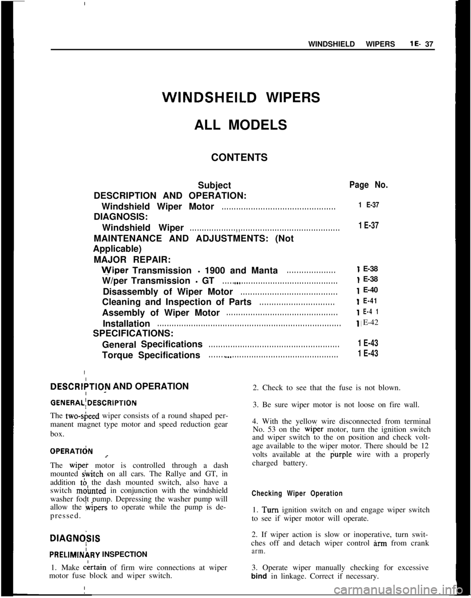
WINDSHIELD WIPERSlE- 37WINDSHEILD WIPERS
ALL MODELS
CONTENTS
Subject
DESCRIPTION AND OPERATION:
Windshield Wiper Motor. . . . . . . . . . . . . . . . . . . . . . . . . . . . . . . . . . . . . . . . . . . . . . .DIAGNOSIS:
Windshield Wiper
. . . . . . . . . . . . . . . . . . . , , . . . . . . . . . . . . . . . . . . . . . . . . . . . . . . . . . . . . . . . . .MAINTENANCE AND ADJUSTMENTS: (Not
Applicable)
MAJOR REPAIR:Wiper Transmission
- 1900 and Manta. . . . . . . . . . . . . . . . . . . .W/per Transmission
- GT. . . . . a.* . . . . . . . . . . . . . . . . . . . . . . . . . . . . . . . . . . . . . . . .Disassembly of Wiper Motor
. . . . . . . . . . . . . . . . . . . . . . . . . . . . . . . . . . . . . . . .Cleaning and Inspection of Parts
. . . . . . . . . . . . . . . . . . . . . . . . . . . . . . .Assembly of Wiper Motor
. . . . . . . . . . . . . . . . . . . . . . . . . . . . . . . . . . . . . . . . . . . . . .Installation
. . . . . . . . . . . . . . . . . . . . . . . . . . . . . . . . . . . . . . . . . . . . . . . . . . . . . . . . . . . . . . . . . . . . . . . . . . . .SPECIFICATIONS:
GeneralSpecifications
. . . . . . . . . . . . . . . . . . . . . . . . . . . . . . . . . . . . . . . . . . . . . . . . . . . . . .Torque Specifications
. . . . . . . a.. . . . . . . . . . . . . . . . . . . . . . . . . . . . . . . . . . . . . . . . . . . . .
DESCRIPTIOfV AND OPERATION
GENERAL;DESCRlPTlDNThe two-sbeed wiper consists of a round shaped per-
manent magnet type motor and speed reduction gear
box. IOPERATldN
=The wipei motor is controlled through a dash
mounted &itch on all cars. The Rallye and GT, in
addition tb the dash mounted switch, also have a
switch moimted in conjunction with the windshield
washer fodt pump. Depressing the washer pump will
allow the bipers to operate while the pump is de-
pressed. i
DIAGNO;SIS
PRELIMINj9RY INSPECTION
1. Make
c&in of firm wire connections at wiper
motor fuse block and wiper switch.
Page No.
1 E-37
1 E-37E-38
E-38
E-40
E-41
E-4 1E-42
1 E-43
1 E-432. Check to see that the fuse is not blown.
3. Be sure wiper motor is not loose on fire wall.
4. With the yellow wire disconnected from terminal
No. 53 on the
wi@er motor, turn the ignition switch
and wiper switch to the on position and check volt-
age available to the wiper motor. There should be 12
volts available at the durple wire with a properly
charged battery.
Checking Wiper Operation1. Turn ignition switch on and engage wiper switch
to see if wiper motor will operate.
2. If wiper action is slow or inoperative, turn swit-
ches off and detach wiper control
inn from crank
arm.3. Operate wiper manually checking for excessive
bind in linkage. Correct if necessary.
Page 63 of 625
1 E- 421973 OPEL SERVICE MANUAL
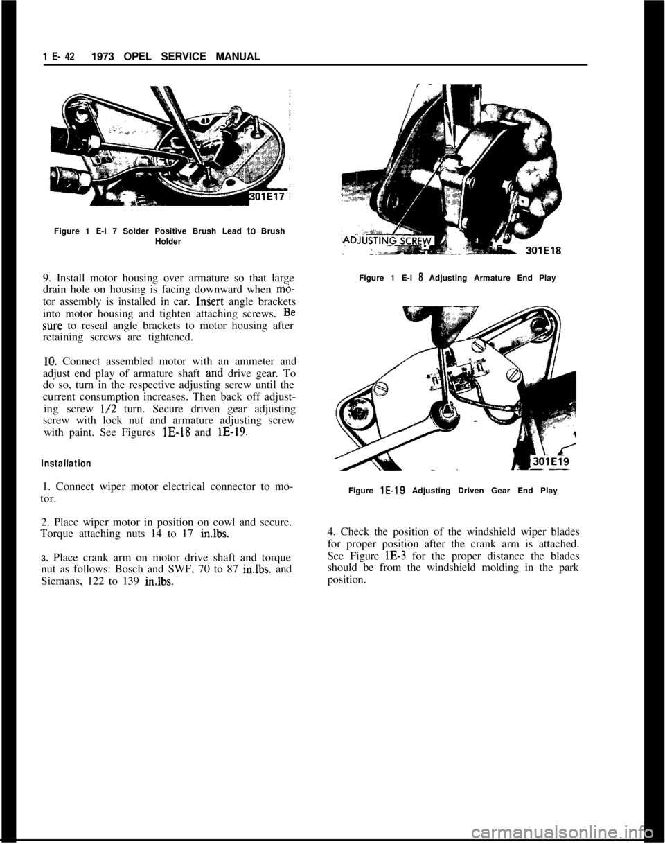
Figure 1 E-l 7 Solder Positive Brush Lead to Brush
Holder
9. Install motor housing over armature so that large
drain hole on housing is facing downward when
mb-tor assembly is installed in car.
InSert angle brackets
into motor housing and tighten attaching screws. Be
sure to reseal angle brackets to motor housing after
retaining screws are tightened.
10. Connect assembled motor with an ammeter and
adjust end play of armature shaft grid drive gear. To
do so, turn in the respective adjusting screw until the
current consumption increases. Then back off adjust-
ing screw
l/2 turn. Secure driven gear adjusting
screw with lock nut and armature adjusting screw
with paint. See Figures lE-18 and lE-19.
Installation1. Connect wiper motor electrical connector to mo-
tor.
2. Place wiper motor in position on cowl and secure.
Torque attaching nuts 14 to 17 in.lbs.
3. Place crank arm on motor drive shaft and torque
nut as follows: Bosch and SWF, 70 to 87 imlbs. and
Siemans, 122 to 139 in.lbs.Figure 1 E-l
8 Adjusting Armature End Play
Figure
lE-19 Adjusting Driven Gear End Play
4. Check the position of the windshield wiper blades
for proper position after the crank arm is attached.
See Figure lE-3 for the proper distance the blades
should be from the windshield molding in the park
position.
Page 76 of 625
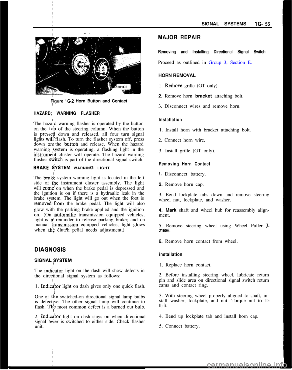
Tigure lG-2 Horn Button and Contact
HAZARD; WARNING FLASHER
The hazard warning flasher is operated by the button
on the
toi, of the steering column. When the button
is
press&@ down and released, all four turn signal
lights
WIU flash. To turn the flasher system off, press
down
oni the button and release. When the hazard
warning
hystem is operating, a flashing light in the
iristrumeht cluster will operate. The hazard warning
flasher
&itch is part of the directional signal switch.
BRAKE $YSTEM WARNING LIGHT
The brak; system warning light is located in the left
side of
tpe instrument cluster assembly. The light
will
come on when the brake pedal is depressed and
the ignition is on if there is a hydraulic leak in the
brake system. The light will go out when the foot is
removed!from the brake pedal. The light will also
glow with the parking brake applied and the ignition
on. (On
Iautomatic transmission equipped vehicles,
light is
a! reminder to release parking brake; and on
manual
fransmission equipped vehicles, light glows
when
the clutch pedal needs adjustment,)
I
DlAGNfXlS
SIGNAL SYSTEM
The indiLator light on the dash will show defects in
the directional signal system as follows:
1.
Indic
tie switched-on directional signal lamp bulbs
is defective. The other signal lamp will continue to
flash.
Thi most common defect is a burned out bulb.
2.
Indicdtor light on dash stays on when directional
signal
leier is switched to either side. Check flasher
unit. I
SIGNAL SYSTEMSlG- 55
MAJOR REPAIR
Removing and Installing Directional Signal Switch
Proceed as outlined in Group 3, Section E.
HORN REMOVAL
1. Remove grille (GT only).
2. Remove horn bracket attaching bolt.
3. Disconnect wires and remove horn.
Installation
1. Install horn with bracket attaching bolt.
2. Connect horn wire.
3. Install grille (GT only).
Removing Horn Contact
1. Disconnect battery.
2. Remove horn cap.
3. Bend lockplate tabs down and remove steering
wheel nut, lockplate, and washer.
4. Mark shaft and wheel hub for reassembly align-
ment.
5. Remove steering wheel using Wheel Puller
J-
21686.
6. Remove horn contact from wheel.
installation
1. Replace horn contact.
2. Before installing steering wheel, lubricate return
pin and slide area on directional signal switch return
cams and contact ring.
3. With steering wheel properly aligned to shaft, in-
stall washer, lockplate, and nut. Torque nut to 15
lb.ft.
4. Bend up lockplate tab and install horn cap.
5. Connect battery.
Page 84 of 625
I
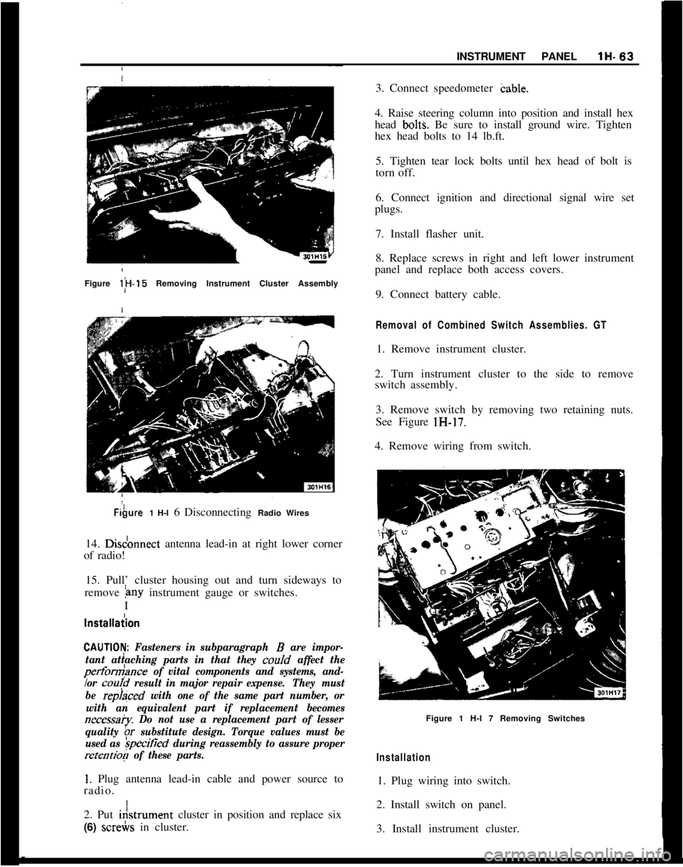
,INSTRUMENT PANELlH-63Figure l;H-15 Removing Instrument Cluster AssemblyFibure1 H-l 6 Disconnecting Radio Wires
14. Disdonnect antenna lead-in at right lower corner
of radio!
15. Pull’ cluster housing out and turn sideways to
remove
&~y instrument gauge or switches.
I
lnstallaiion
CAUTlOI$ Fasteners in subparagraph B are impor-
tant attaching parts in that they coo/d
affect the
perform>nce of vital components and systems, and-
/or
cou!d result in major repair expense.They must
be
repraced with one of the same part number, or
with an equivalent part if replacement becomes
necessa?y. Do not use a replacement part of lesser
quality
br substitute design. Torque values must be
used as
&ified during reassembly to assure proper
retention of these parts.
1. Plug antenna lead-in cable and power source to
radio. I
2. Put i&trument cluster in position and replace six
(6) screbs in cluster.3. Connect speedometer cable.
4. Raise steering column into position and install hex
head
bolt% Be sure to install ground wire. Tighten
hex head bolts to 14 lb.ft.
5. Tighten tear lock bolts until hex head of bolt is
torn off.
6. Connect ignition and directional signal wire set
plugs.
7. Install flasher unit.
8. Replace screws in right and left lower instrument
panel and replace both access covers.
9. Connect battery cable.
Removal of Combined Switch Assemblies. GT1. Remove instrument cluster.
2. Turn instrument cluster to the side to remove
switch assembly.
3. Remove switch by removing two retaining nuts.
See Figure lH-17.
4. Remove wiring from switch.
Figure 1 H-l 7 Removing Switches
Installation1. Plug wiring into switch.
2. Install switch on panel.
3. Install instrument cluster.
Page 125 of 625
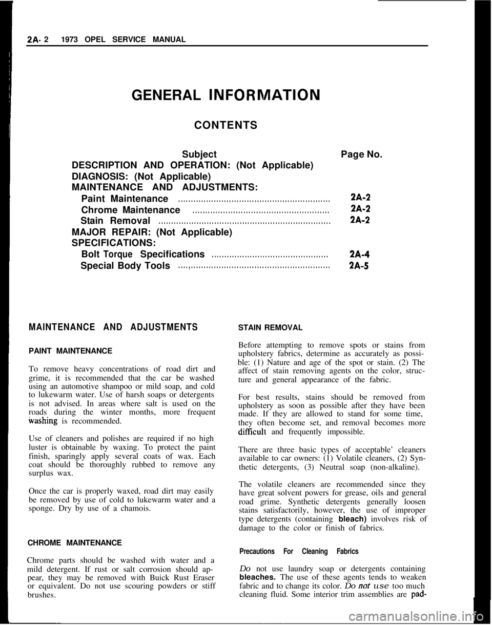
I2A- 21973 OPEL SERVICE MANUAL
GENERAL INFORlVlATION
CONTENTS
SubjectPage No.
DESCRIPTION AND OPERATION: (Not Applicable)
DIAGNOSIS: (Not Applicable)
MAINTENANCE AND ADJUSTMENTS:
PaintMaintenance. . . . . . . . . . . . . . . . . . . . . . . . . . . . . . . . . . . . . . . . . . . . . . . . . . . . . . . . . . . .2A-2
ChromeMaintenance
. . . . . . . . . . . . . . . . . . . . . . . . . . . . . . . . . . . . . . . . . . . . . . . . . . . . . .2A-2
StainRemoval
. . . . . . . . . . . . . . . . . . . . . . . . . . . . . . . . . . . . . . . . . . . . . . . . . . . . . . . . . . . . . . . . . . . .2A-2
MAJOR REPAIR: (Not Applicable)
SPECIFICATIONS:
Bolt
TorqueSpecifications. . . . . . . . . . . . . . . . . . . . . . . . . . . . . . . . . . . . . . . . . . . . . .2A-4
Special Body Tools
. . . . , . . . . . . . . . . . . . . . . . . . . . . . . . . . . . . . . . . . . . . . . . . . . . . . . . . . . . . .2A-5
MAINTENANCE AND ADJUSTMENTSPAINT MAINTENANCE
To remove heavy concentrations of road dirt and
grime, it is recommended that the car be washed
using an automotive shampoo or mild soap, and cold
to lukewarm water. Use of harsh soaps or detergents
is not advised. In areas where salt is used on the
roads during the winter months, more frequentwashing is recommended.
Use of cleaners and polishes are required if no high
luster is obtainable by waxing. To protect the paint
finish, sparingly apply several coats of wax. Each
coat should be thoroughly rubbed to remove any
surplus wax.
Once the car is properly waxed, road dirt may easily
be removed by use of cold to lukewarm water and a
sponge. Dry by use of a chamois.
CHROME MAINTENANCE
Chrome parts should be washed with water and a
mild detergent. If rust or salt corrosion should ap-
pear, they may be removed with Buick Rust Eraser
or equivalent. Do not use scouring powders or stiff
brushes.STAIN REMOVAL
Before attempting to remove spots or stains from
upholstery fabrics, determine as accurately as possi-
ble: (1) Nature and age of the spot or stain. (2) The
affect of stain removing agents on the color, struc-
ture and general appearance of the fabric.
For best results, stains should be removed from
upholstery as soon as possible after they have been
made. If they are allowed to stand for some time,
they often become set, and removal becomes more
diffxult and frequently impossible.
There are three basic types of acceptable’ cleaners
available to car owners: (1) Volatile cleaners, (2) Syn-
thetic detergents, (3) Neutral soap (non-alkaline).
The volatile cleaners are recommended since they
have great solvent powers for grease, oils and general
road grime. Synthetic detergents generally loosen
stains satisfactorily, however, the use of improper
type detergents (containing bleach) involves risk of
damage to the color or finish of fabrics.
Precautions For Cleaning FabricsDo not use laundry soap or detergents containing
bleaches. The use of these agents tends to weaken
fabric and to change its color. Do
not use too much
cleaning fluid. Some interior trim assemblies are pad-
Page 127 of 625
fabric to dry thoroughly; then rub lightly with a
clean cloth dipped in a volatile cleaner. This is the
only further treatment recommended.
Soap and water are not recommended since they will
probably set the stain and cause a permanent dis-
coloration. Drying the fabric by means of heat (such
as the use of an iron) is not recommended.
6. Grease and 02 If grease has been spilled on the
material, as much as possible should be remove by
scraping with a dull knife or spatula before further
treatment is attempted.
Grease and oil stains may be removed by rubbing
lightly with a clean cloth saturated with a volatile
cleaner. Be sure all motions are toward the center of
the stained area to decrease the possibility of spread-
ing the stain.
7. Ice Cream. The same procedure is recommended
for the removal of ice cream stains as that used in
removing fruit stains.
If the stain is persistent, rubbing the spot with a cloth
wet with soap suds (mild neutral soap) may be used
to some advantage after the initial treatment with hot
water. This soap treatment should be followed with
a rinsing, by rubbing with a clean cloth wet with cold
water. After this dries, rubbing lightly with a cloth
wet with volatile cleaner will clear up the last of the
stain, by removing fatty or oily matter.
8.Vomit. Sponge with a clean cloth, dipped in clear
cold water. After most of the stain has been removed
in this way wash lightly with soap (mild neutral),
using a clean cloth and lukewarm water. Then rub
with another clean cloth dipped in cold water. If any
of the stain remains after this treatment, gently rub
clean with a cloth moistened with a volatile cleaner.
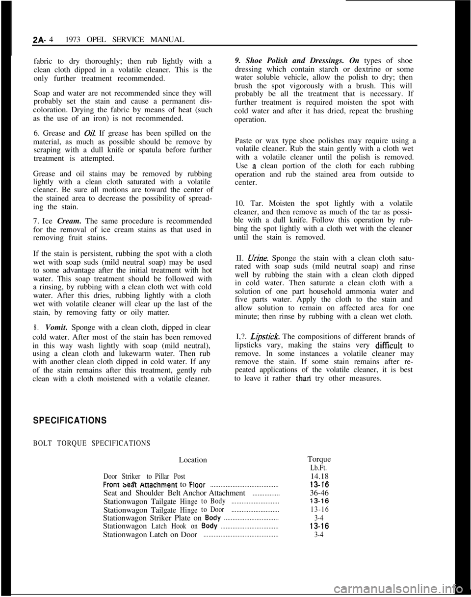
SPECIFICATIONS
BOLT TORQUE SPECIFICATIONSLocation
DoorStriker toPillarPostr .^ ...r.ZA- 41973 OPEL SERVICE MANUAL
9. Shoe Polish and Dressings. On types of shoe
dressing which contain starch or dextrine or some
water soluble vehicle, allow the polish to dry; then
brush the spot vigorously with a brush. This will
probably be all the treatment that is necessary. If
further treatment is required moisten the spot with
cold water and after it has dried, repeat the brushing
operation.
Paste or wax type shoe polishes may require using a
volatile cleaner. Rub the stain gently with a cloth wet
with a volatile cleaner until the polish is removed.
Use
;a clean portion of the cloth for each rubbing
operation and rub the stained area from outside to
center.
10. Tar. Moisten the spot lightly with a volatile
cleaner, and then remove as much of the tar as possi-
ble with a dull knife. Follow this operation by rub-
bing the spot lightly with a cloth wet with the cleaner
until the stain is removed.
II. .X&e. Sponge the stain with a clean cloth satu-
rated with soap suds (mild neutral soap) and rinse
well by rubbing the stain with a clean cloth dipped
in cold water. Then saturate a clean cloth with a
solution of one part household ammonia water and
five parts water. Apply the cloth to the stain and
allow solution to remain on affected area for one
minute; then rinse by rubbing with a clean wet cloth.
I,?.
L,ipslick. The compositions of different brands of
lipsticks vary, making the stains very
diff%cult to
remove. In some instances a volatile cleaner may
remove the stain. If some stain remains after re-
peated applications of the volatile cleaner, it is best
to leave it rather thari try other measures.
Torque
Lb.Ft.
wont saar twacnment to war........................................Seat andShoulderBelt Anchor Attachment
................StationwagonTailgate
HingetoBody............................StationwagonTailgate
HingetoDoor............................Stationwagon Striker Plate on
Body................................Stationwagon
LatchHookonBody..................................Stationwagon Latch on Door
............................................14.18
_^ _^13-1036-46
13-16
13-16
3-4
13-16
3-4