torque OPEL GT-R 1973 Service Manual
[x] Cancel search | Manufacturer: OPEL, Model Year: 1973, Model line: GT-R, Model: OPEL GT-R 1973Pages: 625, PDF Size: 17.22 MB
Page 550 of 625
REFRIGERANT COMPONENTS ALL MODELS9s. 41
BIower Operating Normal Check for the following:Restriction or leakage in air ducts, A/C outlets not
opening.2. Do not carry cylinder in passenger compartment
of car.3. Do not subject cylinder to high temperatures.
MAINTENANCE AND ADJUSTMENTS4. Do not weld or steam clean on or near cylinder.
5. Do not fill cylinder completely.
GENERAL SERVICE INFORMATION AND SAFETY
PRECAUTIONS6. Do not discharge vapor into area where flame is
exposed or directly into engine air intake.
General InformationAll subassemblies are shipped sealed and dehy-
drated. They are to remain sealed until just prior to
making connections, and should be at room tempera-
ture before uncapping. This prevents condensation of
moisture from air that enters the system.
All precautions should be taken to prevent damage
to fittings or connections. Even minute damage to a
connection could cause it to leak. Any fittings with
grease or dirt on them should be wiped clean with a
cloth dipped in alcohol.
Do not clean fitting or hoses with solvents because
they are contaminants. If dirt, grease or moisture
gets inside the pipes or hoses and cannot be removed,the pipe or hose is to be replaced. Use a small amount
of clean refrigeration oil on all tube and hose con-
necting joints, and lubricate the
“0” ring gasket with
this oil before assembling the joint. The oil will help
in effectitig a leak-proofjoint and assist the
“0” ring
to slip into the proper location without being cut or
damaged. Always use new
“0” rings.
When tightening joints, use a second wrench to hold
the stationary part of the connection to prevent
twisting and to prevent hose kinking. Kinked hoses
are apt to transmit noise and vibration. Tighten all
connections in accordance with recommended
torques (see Division VI, Specifications).7. Do not expose eyes to liquid
- WEAR SAFETY
GOGGLES whenever discharging, charging or leak
testing system.
CHARGING AND DISCHARGING SYSTEMRemoval of any part in the refrigerant circuit will
require discharging of the entire system.
Discharging the System1. Remove caps from gauge fittings on the compres-
sor adapter fitting on the compressor.
2. With both valves on manifold gauge set (J-5725-
04) closed (clockwise), attach manifold to the com-
pressor adapter fitting on the compressor, using
J-5420 valve adapter at suction gauge fitting and
J-9459 valve adapter at discharge gauge fitting. See
Figure
9B-41.3. Fully open high pressure valve on manifold gauge
set to allow escape of refrigerant from system
through the manifold gauge set and out the center
fitting and hose. (Place end of hose in clean container
to collect oil loss due to rapid discharge of system).
4. When hissing ceases, indicating all refrigerant
has escaped, close high pressure valve on manifold
gauge set by turning valve clockwise.
Do not connect receiver-dehydrator assembly until
all other connections have been made. This is neces-
sary to itisure maximum moisture removal from sys-
tem.It is important that air conditioning hoses do not rest
on or contact body sheet metal except where neces-
sary. Because of the high frequency at which the
compressor operates, the passenger compartment is
susceptible to transfer of noise.
Evacuating the SystemWhen the refrigeration system is depressurized and
opened for service, some air will enter the lines, re-
gardless of how quickly openings are capped. In
or-der to remove this air and as much as possible of the
moisture it contains, the complete system must be
evacuated. Evacuating is merely the process of
removing all air from the system, thereby creating a
vacuum in the system.
Safety PiecautionsThe following safety precautions should always be
followed~,when servicing refrigerant charged compo-nents:Under no circumstances should alcohol be used in
the system in an attempt to remove moisture,
regard-less of the successful use of alcohol in other refrigera-
tion systems.
Preparations for Evacuating Complete System
1. Do not leave Refrigerant-12 cylinder uncapped.
1. Check the low pressure gauge for proper calibra-
Page 558 of 625
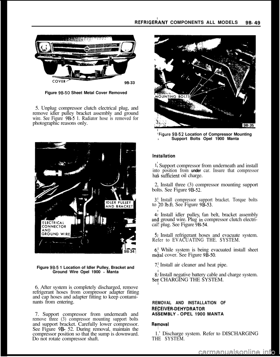
REFRlGEdANT COMPONENTS ALL MODELS96-49Figure 96.50 Sheet Metal Cover Removed
5. Unplug compressor clutch electrical plug, and
remove idler pulley bracket assembly and ground
wire. See Figure 9B-5 1. Radiator hose is removed forphotographic reasons only.
(Figure 98.52 Location of Compressor Mounting
,
Support Bolts Opel 1900 Manta
I
Figure 98-5 1 Location of Idler Pulley, Bracket and
Ground Wire Opel 1900
- Manta
6. After system is completely discharged, remove
refrigerant hoses from compressor adapter fitting
and cap hoses and adapter fitting to keep contami-
nants from entering.
7. Support compressor from underneath and
remove three (3) compressor mounting support boltsand support bracket. Carefully lower compressor.
See Figure
9B- 52. During removal, maintain the
compressor position so that the sump is downward.
Do not rotate compressor shaft.
1: Support compressor from underneath and install
into position from under car. Insure that compressor
haS sutXcient oil charge.
2, Install three (3) compressor mounting support
bolts. See Figure
9B-52.I
3! Install compressor support bracket. Torque boltsto
?O lb.ft. See Figure 9B-53.
4.: Install idler pulley fan belt, bracket assemblyan8 ground wire. Plug
‘In compressor clutch electri-
cal! plug. See Figure
9B-54.
5! Install refrigerant hoses and evacuate system.
Refer to EVACUATING THE. SYSTEM.
6.’ While system is being evacuated install sheet
m&l cover. See Figure 9B-50.
7.1 Install air cleaner and heat pipe.
S! Install negative battery cable and charge system.
Se: CHARGING THE SYSTEM.
REMOVAL AND INSTALLATION OF
REtiEWEFt-DEHYDRATORAS:EMBLY
- OPEL 1900 MANTA
I
R~l!lOV~lI1.’ Discharge system. Refer to DISCHARGING
THE SYSTEM.
Page 565 of 625
98-56 1973 OPEL SERVICE MANUAL
oil cooler lines to lower radiator tank. It is essential
that no dirt enters the oil lines. When tightening oil
lines hold connectors on lower radiator tank with
pliers to avoid leakages. Ensure that no dirt enters oil
cooler. Torque to 11-15 Ibs. ft.
7. Install fan shroud.
8. Install upper radiator hose.
9. Install lower radiator hose and add collected coo-
lant.
All Opel
1900’s and Manta’s are provided with a
radiator initial fill of an anti-freeze solution contain-
ing corrosion inhibitor. The anti-freeze has either a
glycol or glycerin base and protects the engine
against freezing, down to minus 22 degrees F. (minus
30 degrees C.). Before the start of the cold season,
coolant must be checked with a hydrometer and if
necessary, brought to the necessary specific gravity
by adding anti-freeze. Anti-freeze added, must have
a glycol or glycerin base. As the specific gravities of
all anti-freeze solutions having a glycol or glycerin
base are practically the same, the hydrometer can be
used for all these types. Because of the tolerances of
the hydrometer, or slight differences in specific
gravity, variations of plus or minus 5 degrees can be
expected. Coolant must be checked at a temperature
of plus 68 degrees F. (plus 20 degrees C.).
IO. Install negative battery cable and air cleaner.
11. Charge system. Refer to CHARGING SYS-
TEM.
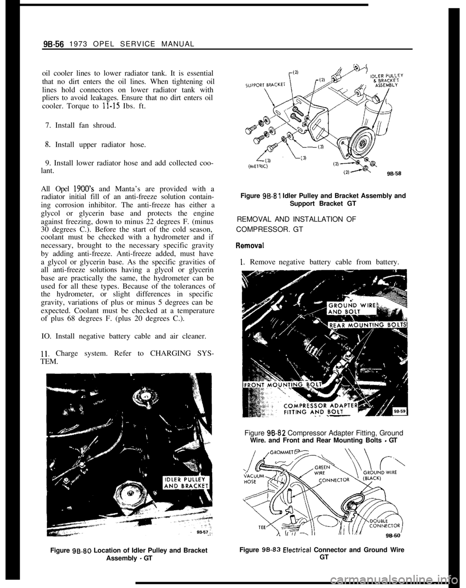
Figure 99.80 Location of Idler Pulley and Bracket
Assembly
- GTFigure 99.81 Idler Pulley and Bracket Assembly and
Support Bracket GT
REMOVAL AND INSTALLATION OF
COMPRESSOR. GT
I. Removenegative battery cable from battery.
Figure 98-82 Compressor Adapter Fitting, Ground
Wire. and Front and Rear Mounting Bolts
- GT
Figure 99.83
Elecirical Connector and Ground Wire
GT
Page 575 of 625
9B-66 1973 OPEL SERVICE MANUAL
LEAK TEST
FIXTURE
\ Js - s ---Y623
\COMPRESSOR
ADAPTERS
J-5420
USE LINE ONLY
DURING
-
COMPRESSOR
SEAL TEST
-4
-
It-’rDISCHARGE LINE
-
LOW PRESSUREHIGt
GAGE
4
PRESSURE
GAGE
(TOP VIEW)
GAGE
*-LINE (3)
J-54 18
GAGE SET
REFRIGERANT
J-5725-01
-CYLINDER
LMANIFOLD AND
9&86
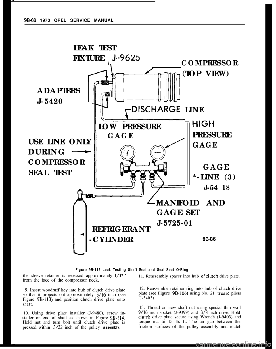
Figure 9B-112 Leak Testing Shaft Seal and Seal Seat O-Ring
the sleeve retainer is recessed approximately l/32”
from the face of the compressor neck. 11. Reassembly spacer into hub ofclutch
drive plate.
9. Insert woodruff key into hub of clutch drive plate
so that it projects out approximately
3/16 inch (see
Figure
9B-113) and position clutch drive plate onto
shaft.
10. Using drive plate installer (J-9480), screw in-
staller on end of shaft as shown in Figure
9B-114.
Hold nut and turn bolt until clutch drive plate is
pressed within
3/32 inch of the pulley assembly.
12. Reassemble retainer ring into hub of clutch drive
plate (see Figure
9B-106) using No. 21 truarc pliers
(J-5403).
13. Thread on new shaft nut using special thin wall
9/16 inch socket (J-9399) and 3/8 inch drive. Hold
clut~ch drive plate secure using Wrench (J-9403) and
torque nut to 15 lb. ft. The air gap between the
friction surfaces of the pulley assembly and clutch
Page 582 of 625
REFRIGERANT COMPONENTS ALL MODELS9B- 73
F
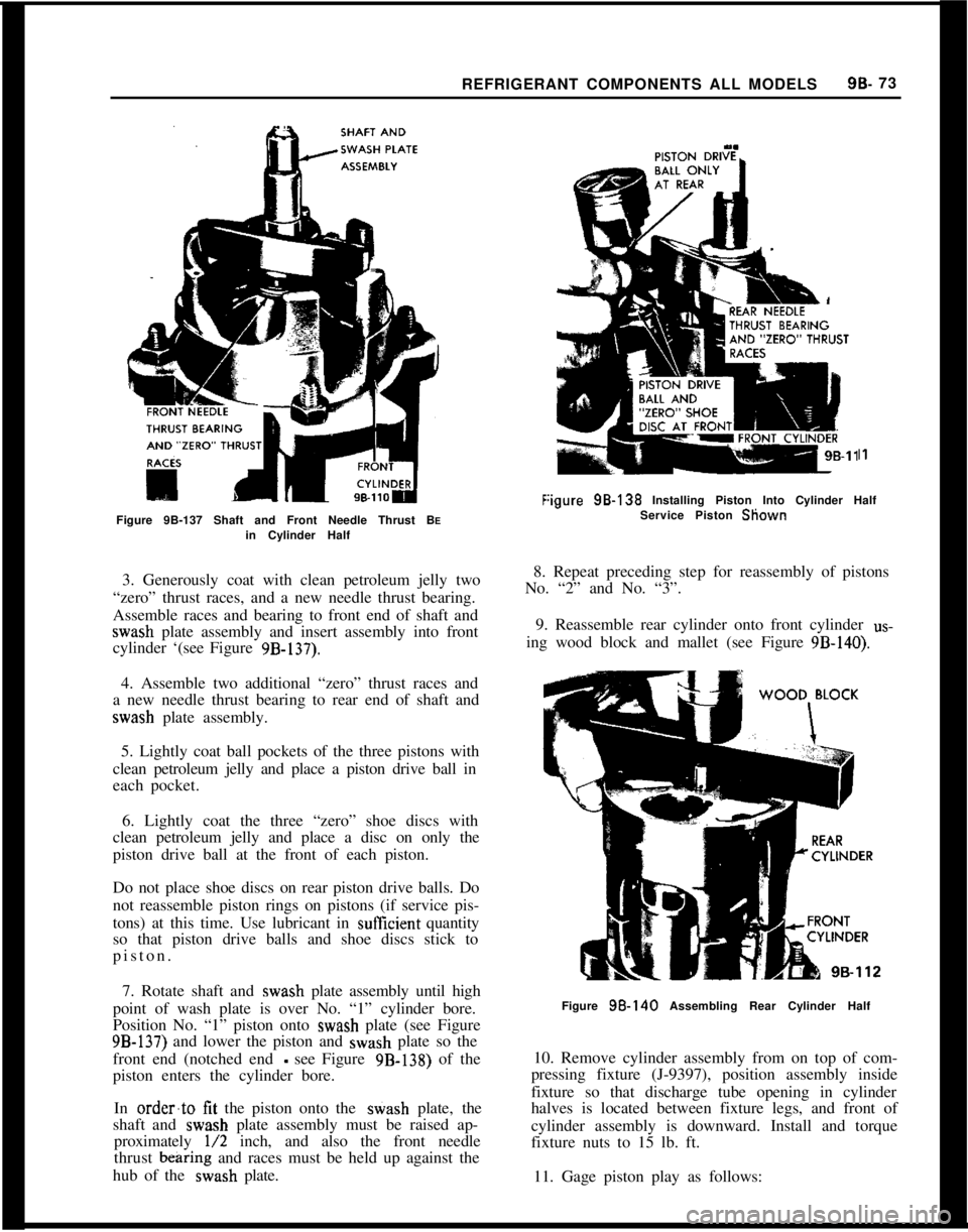
Figure 9B-137 Shaft and Front Needle Thrust BEin Cylinder Half
I1
:igure 98.138 Installing Piston Into Cylinder Half
Service Piston Sliown
3. Generously coat with clean petroleum jelly two
“zero” thrust races, and a new needle thrust bearing.
Assemble races and bearing to front end of shaft and
wash plate assembly and insert assembly into front
cylinder ‘(see Figure
9B-137).
8. Repeat preceding step for reassembly of pistons
No. “2” and No. “3”.
9. Reassemble rear cylinder onto front cylinder
us-
ing wood block and mallet (see Figure 9B-140).
4. Assemble two additional “zero” thrust races and
a new needle thrust bearing to rear end of shaft and
wash plate assembly.
5. Lightly coat ball pockets of the three pistons with
clean petroleum jelly and place a piston drive ball in
each pocket.
6. Lightly coat the three “zero” shoe discs with
clean petroleum jelly and place a disc on only the
piston drive ball at the front of each piston.
Do not place shoe discs on rear piston drive balls. Do
not reassemble piston rings on pistons (if service pis-
tons) at this time. Use lubricant in
sufEcient quantity
so that piston drive balls and shoe discs stick to
piston.
7. Rotate shaft and
wash plate assembly until high
point of wash plate is over No. “1” cylinder bore.
Position No. “1” piston onto
wash plate (see Figure
9B-137) and lower the piston and wash plate so the
front end (notched end
- see Figure 9B-138) of the
piston enters the cylinder bore.
In
order’to tit the piston onto the stiash plate, the
shaft and
wash plate assembly must be raised ap-
proximately
l/2 inch, and also the front needle
thrust
bearing and races must be held up against the
hub of the
wash plate.
Figure 98.140 Assembling Rear Cylinder Half
10. Remove cylinder assembly from on top of com-
pressing fixture (J-9397), position assembly inside
fixture so that discharge tube opening in cylinder
halves is located between fixture legs, and front of
cylinder assembly is downward. Install and torque
fixture nuts to 15 lb. ft.
11. Gage piston play as follows:
Page 588 of 625
REFRIGERANT COMPONENTS ALL MODELS9B- 79
HELL TO HEAD
O-RING(BE SURE
INSIDE SHELL
GRASP FRON
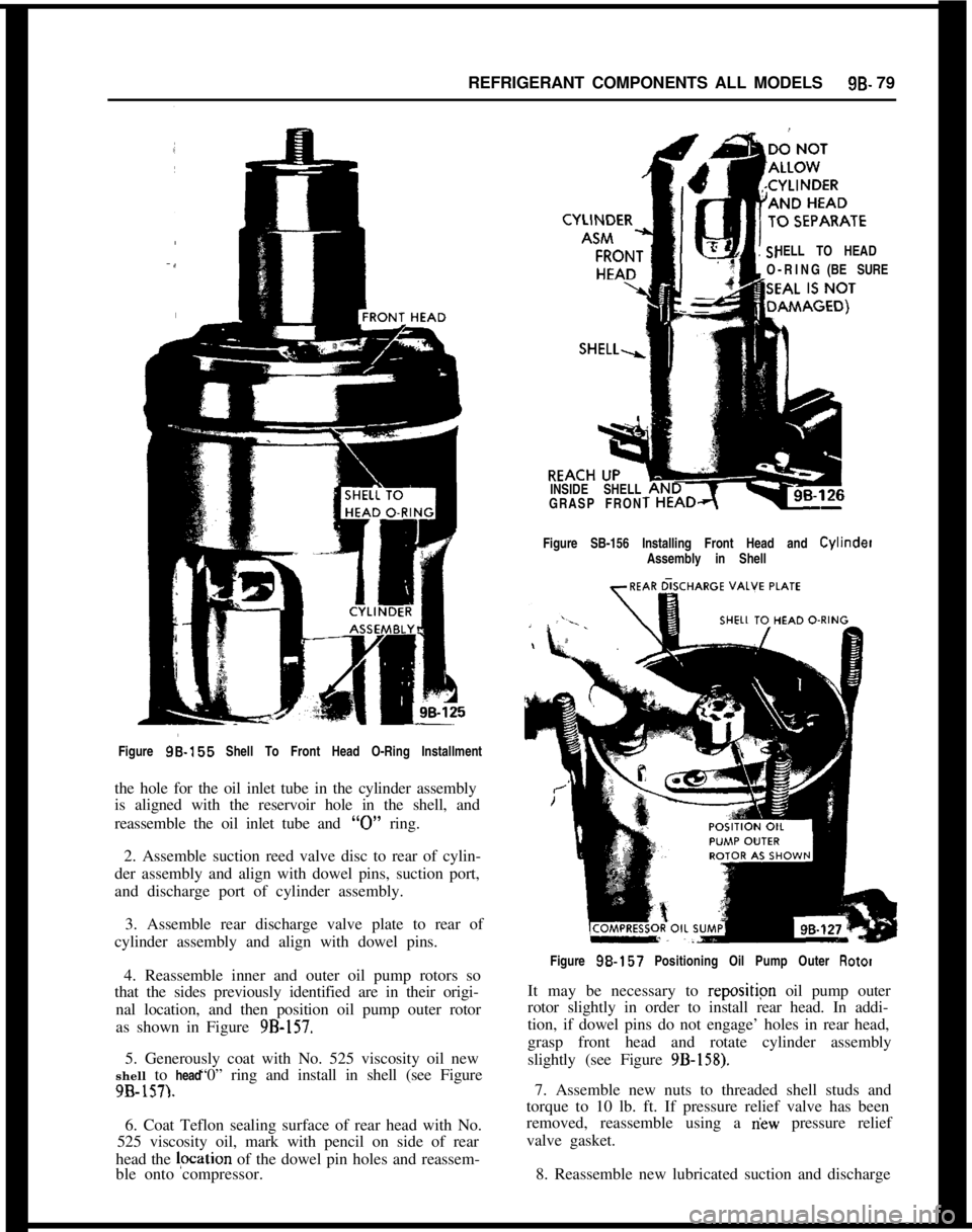
Figure SB-156 Installing Front Head and Cylinder
Assembly in Shell
Figure
96-155 Shell To Front Head O-Ring Installment
the hole for the oil inlet tube in the cylinder assembly
is aligned with the reservoir hole in the shell, and
reassemble the oil inlet tube and
“0” ring.
2. Assemble suction reed valve disc to rear of cylin-
der assembly and align with dowel pins, suction port,
and discharge port of cylinder assembly.
3. Assemble rear discharge valve plate to rear of
cylinder assembly and align with dowel pins.
4. Reassemble inner and outer oil pump rotors so
that the sides previously identified are in their origi-
nal location, and then position oil pump outer rotor
as shown in Figure
9B-157.5. Generously coat with No. 525 viscosity oil new
“0” ring and install in shell (see Figure shell to head
9B-157).6. Coat Teflon sealing surface of rear head with No.
525 viscosity oil, mark with pencil on side of rear
head the lpcation of the dowel pin holes and reassem-
ble onto compressor.Figure
98.157 Positioning Oil Pump Outer Rotor
It may be necessary to repositipn oil pump outer
rotor slightly in order to install rear head. In addi-
tion, if dowel pins do not engage’ holes in rear head,
grasp front head and rotate cylinder assembly
slightly (see Figure
9B-158).7. Assemble new nuts to threaded shell studs and
torque to 10 lb. ft. If pressure relief valve has been
removed, reassemble using a
riew pressure relief
valve gasket.
8. Reassemble new lubricated suction and discharge
Page 591 of 625
r98-82 1973 OPEL SERVICE MANUAL
SPECIFICATIONS
Tightening Specifications
Part
Location
NutDrivePlateNut toCompressorShaft..............................
NutRear Head to Shell................................................................
CaPSchraderServiceValve......................................................
Compressor Specifications
Torque
Lb. Ft.
15
21
5Type
..............................................................................................Six Cylinder Axial Opposed
Make
............................................................................................................................Frigidaire
Effective Displacement (Cu. In.)
..........................................................................................
9.2Oil
..........................................................................................................................525 Viscosity
Oil Content (New)
....................................................................................................10 Fl. Oz.
Air Gap Between Clutch Drive Plate and Pulley
......................................0.022 to 0.057 In.
Clutch Type
................................................................................................................h4agnetic
Belt Tension
..............................................................................................1 lo-125 Lbs. Irritial
....................................................................................................................80 Lbs. Retension
Pipe and Hose Connection Torque Chart
Metal TubeThread andSteel TubingAluminum orNominal Torque
I
Outside Dia.Fitting SizeTorqueCopper TubingWrench Span
Lb. Ft.Torque
Lb. tit.
5-7
General SpecificationsThermostat Opening Temperature
.._.....,,,...__....,,.............................................................. 189
Capacity of Cooling System With Air Conditioner (Quarls)
.,,..___....___............... 6 (Approx.)Type of Refrigerant
.___,,,._...,.,,,.__.....,,,.......,,,,.......,,,...................,,,......,,,............ Refrigerant 12
Refrigerant Capacity (Fully Charged)
Opel
1900-Manta,,._....,,,,._...._.,,,,.......,,,........,,............................................................2 Lbs.
GT
,..__..,..,..__..,,,.......,,,,.......,,,........,,,.,......,,,,,......,,.,,........,,.......,,..........,,............... 2 l/4 Lbs.
Functional Test Procedures1. Place transmission in park for automatics and in
neutral for manuals. Apply hand brake.
2. Turn blower switch to HI position,
3. Turn temperature switch to MAX position-.
4. Run engine at 2000 RPM for ten (10) minutes with
car doors and windows closed and the hood up. Place
a commercial high volumn fan in front of condenser
if head pressure should exceed 250 psig.A commercial high volumn fan should be placed in
front of the condenser at high ambients to bring the
pressures to within the limits specified in the Func-
tional Charts. When testing the Opel 1900 and
Man& a thermometer should be placed in a position
to read the temperature of the air discharging from
the right-hand A/C outlet. When testing the GT, a
thermometer should be placed in a position to read
the temperature of the air discharging, from the left-
rear
,A /c outlet.
Page 616 of 625
9C-108 1973 OPEL SERVICE MANUAL
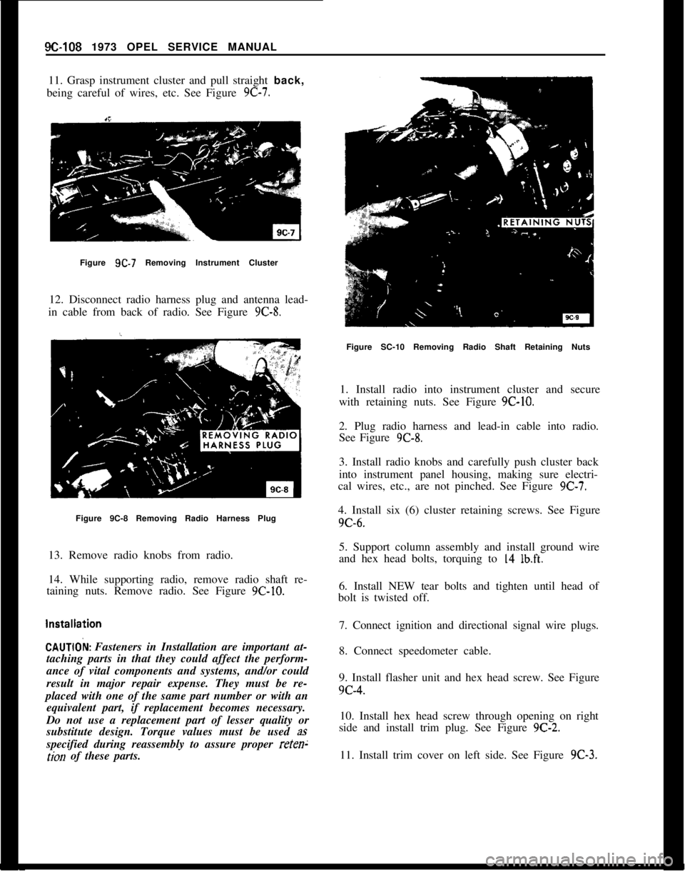
11. Grasp instrument cluster and pull straight back,
being careful of wires, etc. See Figure 9C-7.
Figure 9C-7 Removing Instrument Cluster
12. Disconnect radio harness plug and antenna lead-
in cable from back of radio. See Figure
9C-8.
Figure 9C-8 Removing Radio Harness Plug
13. Remove radio knobs from radio.
14. While supporting radio, remove radio shaft re-
taining nuts. Remove radio. See Figure
9C-10.
CAUTlOk Fasteners in Installation are important at-
taching parts in that they could affect the perform-
ance of vital components and systems, and/or could
result in major repair expense. They must be re-
placed with one of the same part number or with an equivalent part, if replacement becomes necessary.
Do not use a replacement part of lesser quality or
substitute design. Torque values must be used
as
specified during reassembly to assure proper
reten;
tion of these parts.
Figure SC-10 Removing Radio Shaft Retaining Nuts
1. Install radio into instrument cluster and secure
with retaining nuts. See Figure
9C-10.
2. Plug radio harness and lead-in cable into radio.
See Figure
9C-8.
3. Install radio knobs and carefully push cluster back
into instrument panel housing, making sure electri-
cal wires, etc., are not pinched. See Figure
9C-7.
4. Install six (6) cluster retaining screws. See Figure
9C-6.
5. Support column assembly and install ground wire
and hex head bolts, torquing to
14 lb.ft.
6. Install NEW tear bolts and tighten until head of
bolt is twisted off.
7. Connect ignition and directional signal wire plugs.
8. Connect speedometer cable.
9. Install flasher unit and hex head screw. See Figure
9c-4.10. Install hex head screw through opening on right
side and install trim plug. See Figure
9C-2.
11. Install trim cover on left side. See Figure 9C-3.
Page 621 of 625
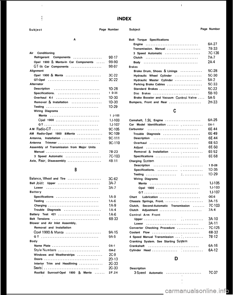
SubjectPage Number
Subject Page Number
A
Air Conditioning Refrigerant Components .................
98.17
Opel 1900
& Manta-In Car Components .....9B-90
GT.ln Car Components..................98-97
Alignment Opel 1900
& Manta .....................3C-22
GT-Opel ..............................
3C-22
Alternator Description ...........................
lD-28
Specifications. .........................1 D-35
Overhaul K-l..........................lD-30
Removal & Installation ..................lD-30
Testing...............................lD-29
Wiring Diagrams
Manta .............................
1 J-105
Opel 1900
..........................lJ-103
GT ................................
lJ-107
AM
Radio-GT............................9C-105
AM Radio-Opel 1900 &Manta ...............
9C-109
Antenna, Installation .......................
9C-111
Antenna Trimmer .........................
9C-110
Assembly of Transmission from Major Units Manual ...............................
78-23
3 Speed Automatic .....................
7C-103
Axle,
R&r, Disassembly ....................48~11
Bolt Torque Specifications
Engine ...............................
6A-27
Transmission. Manual ....................
78-33
3 Speed Automatic .....................
7C-136
Clutch ...............................
7A-7
Body ................................
2A-4
Brakes
Brake Drum, Shoes & Linings .............5C-28
Hydraulic Wheel Cylinder ................
5C-30
Hydraulic Master Cylinder ................
5A-2
Parking Brake Cables .....................
5C-33
Standard Brakes ........................
X-22
Disc Brakes...........................5B-10
Brake Booster and Vacuum
Coritrol Valve ....5A-5
Bumpers, Front and Rear ...................
ZH-33
C
B
Balance,,Wheel and Tire....................3G-62
Ball
J&tUpper .........................3A-7
Lower ...............................
3A-7
Battery
Specifications ..........................
lA-9
Testing...............................lA-6
Charging ..............................lA-9
Trouble Diagnosis ......................lA-4
Battery Test 421.........................l A-6
Belt Tensions ............................
68.33
Blower and Air Inlet Assembly, Removal and Installation
Owl 1900&Manta.....................9A-15
GT
.: ................................9A-5
Body Name Plate ............................
OA-1
Style’Numbers ......................... OA-2
Windows and Weatherstrips ...............
ZC-9
Doors ................................
ZD-13
Interior Trim and Headlining ..............
26-33
Seatsi................................26-33
Roof&d Sunroof-Opel 1900
& Manta ......2F.24 Camshaft,
1.9L
Engine .....................6A-25
Car Model Identification .......
.,............OA-1
Carburetor..............................6E-44
Trouble Diagnosis ......................
6E-49
Description ...........................
6E-44
Overhaul .............................
6E-53
Adjust ...............................
6E-50
Removal
& Installation ......,............6E-52
Specifications ..........................
6E-58
Charging
System
Description ..............
:............ 1 D-28
Specifications. ............
.,............lD-35
Testing..................:............lD-29
Wiring Diagrams
Manta .............................
lJ-105
Opel 1900 ..........................
lJ.103
GT ................................
lJ-107
Chart Lubrication ........................ OC-5
Chassis Springs, Front. ........
!............3A-15
Clutch, Second-Automatic Transmission .......
7C-103
Clutch Adjustment .........................
7A-4
Control Arm Front Upper ...................
:............3A-10
Lower ...............................
3A-11
Converter Checking Procedure ................
7C-125
Coolant Flow ............................
68-32
4 Speed Manual Transmission ...
!,...........7B-12
Cranking System. See Starting
SyStem
Crankshaft..............................6A-16
Cylinder Head ...............
:............6A-12
D
Description
3.Speed Automatic.....................7C-37
Page 624 of 625
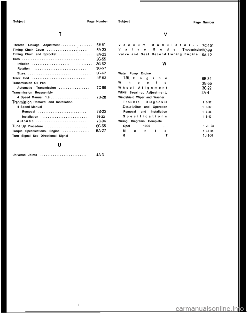
SubjectPage Number1
Throttle Linkage Adjustment........,:.......6E-51
Timing Chain Cover.......................6A-23
Timing Chain and Sprocket.........
':.......6A-23
Tires...................................36-55
Inflation.....................
.;.......3G-62
Rotation.............................36-57
Sizes.........................
........3G-62
Track Rod..............................3F-53
Transmission Oil Pan
Automatic Transmission.................7C-99
Transmission Reassembly
4 Speed Manual. 1.9.....................76-28Tranmission Removal and Installation
4 Speed Manual
Removal...........................7B-22
Installation.........................76-22
Auto&tic............................7c-94Tune’Up Procedure........................66-65
Torque Specifications. Engine...............6A-27
Turn Signal See Directional Signal
Universal Joints..........................4A-3Subject
VPage Number
Vacuum Modulator..7C-101
Valve Body Transmlssmn7C.99
Valve and Seat Reconditioning Engine6A-12
WWater Pump Engine1.9L Engine
Wheels
Wheel Alignment
Whee! Bearing, Adjustment,
Windshield Wiper and Washer:
Trouble Diagnosis:Description and Operation
Removal and Installation
Specifications
Wiring Diagrams Complete
Opel 1900 ._.
Manta
GT
1 E-37
1 E-37
1 E-38
1 E-43
1 J-l 03
1 J-l 05lJ-10768-3436-553C-223A-4