refrigerant type OPEL GT-R 1973 Service Manual
[x] Cancel search | Manufacturer: OPEL, Model Year: 1973, Model line: GT-R, Model: OPEL GT-R 1973Pages: 625, PDF Size: 17.22 MB
Page 533 of 625
9B-24 1973 OPEL SERVICE MANUAL
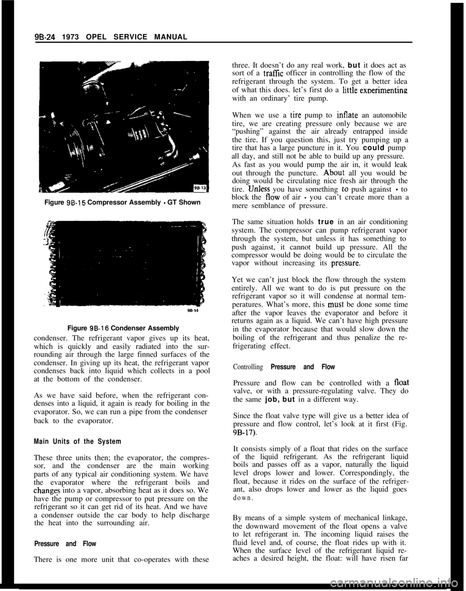
Figure 9B-15 Compressor Assembly - GT Shown
Figure 3B-16 Condenser Assembly
condenser. The refrigerant vapor gives up its heat,
which is quickly and easily radiated into the sur-
rounding air through the large finned surfaces of the
condenser. In giving up its heat, the refrigerant vapor
condenses back into liquid which collects in a pool
at the bottom of the condenser.
As we have said before, when the refrigerant con-
denses into a liquid, it again is ready for boiling in the
evaporator. So, we can run a pipe from the condenser
back to the evaporator.
Main Units of the SystemThese three units then; the evaporator, the compres-
sor, and the condenser are the main working
parts of any typical air conditioning system. We have
the evaporator where the refrigerant boils andchanges into a vapor, absorbing heat as it does so. We
have the pump or compressor to put pressure on the
refrigerant so it can get rid of its heat. And we have
a condenser outside the car body to help discharge
the heat into the surrounding air.
Pressure and FlowThere is one more unit that co-operates with thesethree. It doesn’t do any real work, but it does act as
sort of a traffic officer in controlling the flow of the
refrigerant through the system. To get a better idea
of what this does. let’s first do a li,ttle exoerimentine
with an ordinary’ tire pump.
When we use a
t,ire pump to Sate an automobile
tire, we are creating pressure only because we are
“pushing” against the air already entrapped inside
the tire. If you question this, just try pumping up a
tire that has a large puncture in it. You could pump
all day, and still not be able to build up any pressure.
As fast as you would pump the air in, it would leak
out through the puncture.
Abou~t all you would be
doing would be circulating nice fresh air through the
tire.
1Jnless you have something lo push against - to
block the tlow of air
- you can’t create more than a
mere semblance of pressure.
The same situation holds true in an air conditioning
system. The compressor can pump refrigerant vapor
through the system, but unless it has something to
push against, it cannot build up pressure. All the
compressor would be doing would be to circulate the
vapor without increasing its
pres,sure.Yet we can’t just block the flow through the system
entirely. All we want to do is put pressure on the
refrigerant vapor so it will condense at normal tem-
peratures. What’s more, this
musi: be done some time
after the vapor leaves the evaporator and before it
returns again as a liquid. We can’t have high pressure
in the evaporator because that would slow down the
boiling of the refrigerant and thus penalize the re-
frigerating effect.
Controlling Pressure and FlowPressure and flow can be controlled with a float
valve, or with a pressure-regulating valve. They do
the same job, but in a different way.
Since the float valve type will give us a better idea of
pressure and flow control, let’s look at it first (Fig.
9B-17).It consists simply of a float that rides on the surface
of the liquid refrigerant. As the refrigerant liquid
boils and passes off as a vapor, naturally the liquid
level drops lower and lower. Correspondingly, the
float, because it rides on the surface of the refriger-
ant, also drops lower and lower as the liquid goes
down.By means of a simple system of mechanical linkage,
the downward movement of the float opens a valve
to let refrigerant in. The incoming liquid raises the
fluid level and, of course, the float rides up with it.
When the surface level of the refrigerant liquid re-
aches a desired height, the float: will have risen far
Page 534 of 625
REFRIGERANT COMPONENTS ALL MODELS9B- 2596.15
Figure 95.17 Float Type Flow Valve
enough to close the valve and stop the flow of refrig-
erant liquid.
For the sake of simplicity, we have described the
float and valve action as being in a sort of definite
wide open or tight shut condition. Actually, though,
the liquid level falls rather slowly as the refrigerant
boils away. Likewise, the float goes down gradually
and gradually opens the valve just a crack. New
refrigerant liquid barely seeps in through the
“cracked” valve. At such a slow rate of flow, it raises
the liquid level in the evaporator very slowly.
With that in mind, it is easy to see how it would be
possible for a stabilized condition to exist. By that,
we mean a condition wherein the valve would be/
DIAPHRAGMACTUATINGBACK.UP PLATE
PINS \
t
>IAPHRAGM \
/
BoDyEQUALIZER\4]
PASSAGE
‘!!!ISEATSCkEEN:ARRIAGEORIFICE
AGE SPRINGIER ELEMENT:MOB”LBSPRING SEAT
OUTLET
W-16opened barely enough to allow just exactly the right
amount of refrigerant liquid to enter the freezer to
take the place of that leaving as a vapor.
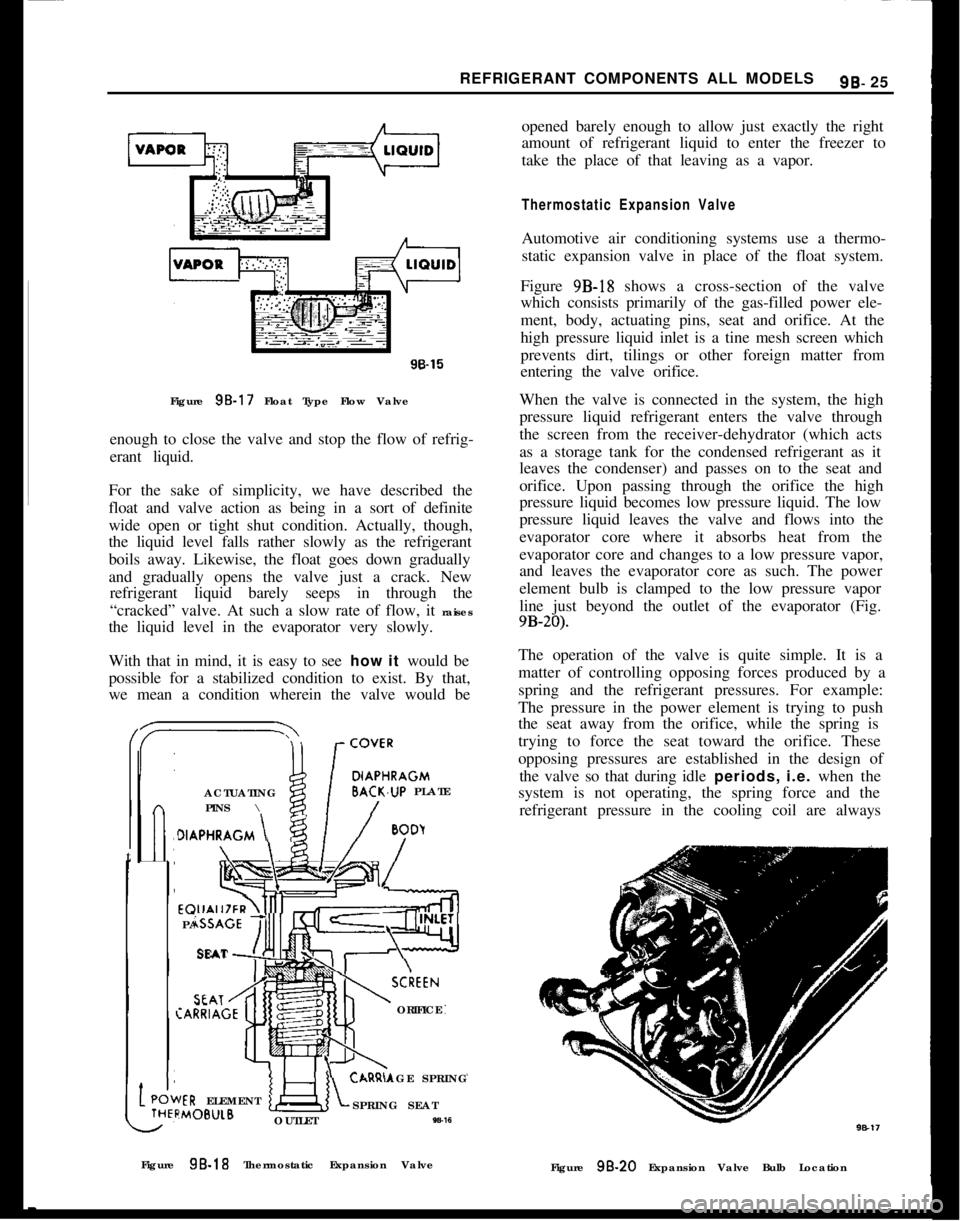
Thermostatic Expansion ValveAutomotive air conditioning systems use a thermo-
static expansion valve in place of the float system.
Figure 9B-18 shows a cross-section of the valve
which consists primarily of the gas-filled power ele-
ment, body, actuating pins, seat and orifice. At the
high pressure liquid inlet is a tine mesh screen which
prevents dirt, tilings or other foreign matter from
entering the valve orifice.
When the valve is connected in the system, the high
pressure liquid refrigerant enters the valve through
the screen from the receiver-dehydrator (which acts
as a storage tank for the condensed refrigerant as it
leaves the condenser) and passes on to the seat and
orifice. Upon passing through the orifice the high
pressure liquid becomes low pressure liquid. The low
pressure liquid leaves the valve and flows into the
evaporator core where it absorbs heat from the
evaporator core and changes to a low pressure vapor,
and leaves the evaporator core as such. The power
element bulb is clamped to the low pressure vapor
line just beyond the outlet of the evaporator (Fig.
9B-20).The operation of the valve is quite simple. It is a
matter of controlling opposing forces produced by a
spring and the refrigerant pressures. For example:
The pressure in the power element is trying to push
the seat away from the orifice, while the spring is
trying to force the seat toward the orifice. These
opposing pressures are established in the design of
the valve so that during idle periods, i.e. when the
system is not operating, the spring force and the
refrigerant pressure in the cooling coil are always
Figure 9B-18 Thermostatic Expansion Valve
Figure
98.20 Expansion Valve Bulb Location
Page 535 of 625
98-26 1973 OPEL SERVICE MANUAL
greater than the opposing pressure in the power ele-
ment. Therefore, the valve remains closed. When the
compressor is started, it will reduce the pressure and
temperature of the refrigerant in the cooling coil to
a point where the vapor pressure in the power ele-
ment becomes the stronger. The seat then moves off
the orifice and liquid starts to flow through the valve
orifice into the cooling coil.
The purpose of the power element is to help deter-
mine the quantity of liquid that is being metered into
the cooling coil. As the temperature of the low pres-
sure line changes at the bulb, the pressure of
the
vapor in the power element changes, resulting in a
change of the position of the seat. For example, if the
cooling coil gets more liquid than is required, the
temperature of the low pressure line is reduced and
the resultant lowering of the bulb temperature
reduces the pressure of the vapor in the power ele-
ment, allowing the seat to move closer to the orifice.
This immediately reduces the amount of liquid leav-
ing the valve. Under normal operation, the power
element provides accurate control of the quantity of
refrigerant to the cooling coil.
To employ our tire pump analogy once more for
clarity, it is the same situation that would exist if you were inflating a tire with a very slow leak. Providing
you pumped the air into the tire as fast as it leaked
out, you would be able to maintain pressure even
though the air would merely be circulating through the tire and leaking out through the puncture.
To Sum Up
So far, we’ve discussed only what each unit in an air
conditioning system does. We’ve learned that the
evaporator is the unit in which liquid refrigerant
soaks up heat from the air, the compressor is a pump
for squeezing this heat out of the vapor, the con-
denser is a radiator for getting rid of the heat, and the
thermostatic expansion valve is a device for regulat-
ing the pressure on the refrigerant. Now, let’s
find
out how the temperature of the cooled air is con-
trolled.
METHOD OF TEMPERATURE CONTROL
To achieve temperature control, the compressor is
run intermittently, automatically turning on and off
as necessary to maintain proper temperature.
Thermostatic Switch
The compressor can be started and stopped au-
tomatically through the use of an electro-magnetic
clutch and a thermostat affected by variations of temperature.
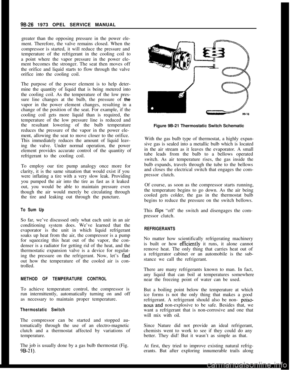
The job is usually done by a gas bulb thermostat (Fig.
9B-21).
Figure 9B-21 Thermostatic Switch Schematic
With the gas bulb type of thermostat, a highly expan-
sive gas is sealed into a metallic bulb which is located
in the air stream as it leaves the evaporator. A small
tube leads from the bulb to a bellows operated switch. As air temperature rises, the gas inside the
bulb expands, travels through the tube to the bellows
and closes the electrical switch that engages the com-
pressor clutch.
Of course, as soon as the compressor starts running,
the temperature begins to go down. As the air being
cooled gets colder, the gas in the thermostat bulb
begins to reduce the pressure on the switch bellows.
This
Ilips “off’ the switch and disengages the com-
pressor clutch.
REFRIGERANTS
No matter how scientifically refrigerating machinery
is built or how
efftciently it runs, it alone cannot
remove heat. The only thing that carries heat out of
a refrigerator cabinet or an automobile is the sub-
stance we call the refrigerant.
There are many refrigerants known to man. In fact,
any liquid that can boil at temperatures somewhere
near the freezing point of water can be used.
But a boiling point below the temperature at which
ice forms is not the only thing that makes a good
refrigerant. A refrigerant should also be non-
poiso-
nowand non-explosive to be safe. Besides that, we
want a refrigerant that is non-corrosive and one that
will mix with oil.
Since Nature did not provide an ideal refrigerant,
chemists went to work to see if they could do any
better. They did! But it wasn’t as simple as that.
At first, they tried to improve existing natural refrig-
erants. But after exploring innumerable trails along
Page 540 of 625
REFRIGERANT COMPONENTS ALL MODELS9B- 31
When adding oil, the container should be exception-
ally clean and dry due to the fact that the refrigera-
tion oil in the container is as moisture-free as it is
possible to make it. Therefore, it will quickly absorb
any moisture with which it comes in contact. For this
same reason the oil container should not be opened
until ready for use and it should be capped immedi-
ately afte;r use.
When it is necessary to open a system, have every-
thing you will need ready and handy so that as little
time as possible will be required to perform the oper-
ation. Don’t leave the system open any longer than
is necessary.
Finally, after the operation has been completed and
the system sealed again, air and moisture should be
evacuated from the system before recharging.
THE PRIMARY CAUSES OF SYSTEM FAILURES
LeaksA shortage of refrigerant causes oil to be trapped in
the evaporator. Oil may be lost with the refrigerant
at point of leakage. Both of these can cause compres-
sor seizure.
Oil circulates in the system with the refrigerant; in
solution with the liquid and in globules with the
vapor. It leaves the compressor by the action of the
pistons and mixes with the refrigerant liquid in the
condenser. The oil then enters the evaporator with
the liquid and, with the evaporator properly flooded,
is returned to the compressor through the low pres-
sure line. Some of the oil returns as globules in the
vapor, but more important, it is swept as a liquid
along the walls of the tubing by the velocity of the
vapor. If the evaporator is starved, the oil cannot
return in sut?icient quantities to keep the compressor
properly lubricated.
High Temperature and PressureAn increase in temperature causes an increase in
pressure. This accelerates chemical instability due to
existing contaminants in the system, and initiates
chemical instability in clean systems. Other results
are brittle hoses,
“0” ring gaskets, and valve dia-
phragms with possible decomposition, broken com-
pressor discharge reeds, and seized compressor
bearings.
A fundamental law of nature accounts for the fact
that when a substance, such as a refrigerant, is in-
creased in temperature, its pressure is also increased.
Any chemical reactions caused by contaminants al-
ready in the system are greatly accelerated as the
temperature increases. A 15 degree rise in tempera-
ture doubles the chemical action. Even in a goodclean system, heat alone can start a chain of harmful
chemical reactions.
While temperature alone can cause the synthetic rub-
ber parts to become brittle and possibly to decom-
pose, the increased pressure can cause them to
rupture or blow.
As the temperature and pressure increases the stress
and strain on the compressor discharge reeds also
increases. This can result in broken reeds. Due to the
effect of the contaminants caused by high tempera-
ture and pressure, compressor bearings can be
caused to seize.
High temperature and pressure are also caused by air
in the system.
Air in the SYstemAir results from a discharged system or careless ser-
vicing procedures. This reduces system capacity and
efficiency and causes oxidation of oil into gum and
varnish.
When a leak causes the system to become dis-
charged, the resulting vacuum within the system will
cause air to be drawn in. Air in the system is a
non-condensable gas and will build up in the con-
denser as it would in an air compressor tank. The
resultant heat produced will contribute to the condi-
tions discussed previously.
Many systems are contaminated and also reduced in
capacity and efficiency by servicemen who either do
not know or are careless regarding proper servicing
procedures.
Too frequently, systems which have been open to the
atmosphere during service operations have not been
properly purged or evacuated. Air is also introduced
into the system by unpurged gauge and charging
lines. Remember that any air in the system is too
much air.
Poor ConnectionsHose clamp type fittings must be properly made.
Hoses should be installed over the sealing flanges and
with the end of the hose at the stop flange. The hose
should never extend beyond the stop flange. Locate
the clamp properly and torque as recommended. Be
especially careful that the sealing flanges are not
nicked or scored or a future leak will result.
When compression fittings are used, over tightening
can cause physical damage to the “0” ring gasket
and will result in leaks. The use of torque and back-
ing wrenches is highly recommended. When making
a connection with compression fittings, the gaskets
should always be first placed over the tube before
Page 542 of 625

REFRIGERANT COMPONENTS ALL MODELS99- 33
That the attraction of the drying material for mois-
ture is so powerful that if the receiver is left open,
moisture will be drawn in from the outside air.
That just one drop of water added to the refrigerantwill start chemical changes that can result in corro-
sion and eventual breakdown of the chemicals in the
system. Hydrochloric acid is the result of an R-12
mixture with water.
That the smallest amount of air in the refrigeration
system may start reactions that can cause malfunc-
tions.
That the drying agent in the receiver-dehydrator is
Activated Silica Alumina (silica-gel).
That
the inert gas in the expansion valve capillary
line is carbon dioxide.
DESCRIPTION OF AIR CONDITIONING
COMPONENTS
Compressor
The compressor is located in the engine compart-
ment. The purpose of the unit is to draw the low
pressure,gas from the evaporator and compress this
gas into a high temperature, high pressure gas. This
action will result in the refrigerant having a higher
temperature than the surrounding air.
The
cortipressor is of basic double action piston de-
sign. Three horizontal double acting pistons make up
a six cylinder compressor (See Figure
9B-162). The
pistons operate in
l-1/2 inch bore and have a l-1/8
inch stroke. A
wash plate keyed to the shaft drives
the pistons. The shaft is belt driven through a mag-
netic clutch and pulley arrangement. An oil pump
mounted at the rear of the compressor picks up oil
from the
botto’m of the compressor and lubricates the
bearings’and other internal parts of the compressor.
Reed type valves at each end of the compressor open
or close to control the flow of incoming and outgoing refrigerant. Two gas tight passages interconnect
chambers of the front and rear heads so that there is
one common suction port, and one common dis-
charge port. The internal parts of the compressor
function, as follows:
1. Suction Valve Reed Discs and Discharge Valve
Plates
_ The two suction valve reed discs and two
discharge valve plates (see Figure
9B-25) operate in
a similar but opposite manner. The discs are com-
posed of three reeds and function to open when the
pistons are on the intake portion of their stroke
(downstroke), and close on the compression stroke.
The reeds allow low pressure gas to enter the cylin- ders. The discharge valve plates also have three
reeds, however, they function to open when the pis- tons are on the compression portion of their stroke
(upstroke), and close on the intake stroke. High pres-
sure gas exits from discharge ports in the discharge
valve plate. Three retainers riveted directly above the
reeds on the valve plate serve to limit the opening of
the reeds on the compression stroke.
SUCTION VALVE
DISCHARGE-VALVE PLATES
Figure
98-25 - Compressor Suction Valve Reed Discs
and Discharge Valve Plates
2. Front and Rear Heads - The front and rear heads
(Figure
9B-26) serve to channel the refrigerant into
and out of the cylinders. The front head is divided
into two separate passages and the rear head is di-
vided into three separate passages. The outer passage
on both the front and rear heads channels high pres-
sure gas from the discharge valve reeds. The middle
passage of the rear head also contains the port open-
ing to the superheat switch cavity. This opening in
the rear head permits the superheat switch to be
affected by suction gas pressure and suction gas tem-
perature for the operating protection of the compres-
sor. The inner passage on the rear head houses the
oil pump inner and outer rotors. A Teflon sealing
material is bonded to the sealing surfaces separating
the passages in the rear head.
“0” rings are used to
affect a seal between the mating surfaces of the heads
and the shell. The front head suction and discharge
passages are connected to the suction and discharge
passages of the rear head by a discharge tube and
suction passage in the
body of the cylinder assembly.
A screen located in the suction port of the rear head
prevents foreign material from entering the circuit.
3. Oil Pump
- An internal tooth outer rotor and
external tooth inner rotor comprise the oil pump.
The pump works on the principle of a rotary type pump. Oil is drawn up from oil reservoir in underside
of shell through the oil inlet tube (see Figure
9B-27)
Page 547 of 625

9B-38 1973 OPEL SERVICE MANUAL
expand and return to the original gaseous state. To
accomplish this transformation it begins to boil.
The boiling action of the refrigerant demands heat.
To satisfy the demand for heat, the air passing over
the core gives up heat to the evaporator and is subse-
quently cooled.\
DIAGNOSIS
GENERAL INFORMATIONThe following is a brief description of the type of
sympton each refrigerant component will evidence if
a malfunction occurs:
Compressor malfunction will appear in one of four
ways: noise, seizure, leakage, or low discharge pres-
sure.Resonant compressor noises are not cause for alarm;
however, irregular noise or rattles may indicate
broken parts or excessive clearances due to wear. To
check seizure, de-energize the magnetic clutch and
check to see if drive plate can be rotated. If rotation
is impossible, compressor is seized. Low discharge
pressure may be due to a faulty internal seal of the
compressor, or a restriction in the compressor.
Low discharge pressure may also be due to an insuffi-
cient refrigerant charge or a restriction elsewhere in
the system. These possibilities should be checked
prior to servicing the compressor. If the compressor
is inoperative; but, is not seized, check to see if cur-
rent is being supplied to the magnetic clutch coil
terminals.
CondenserA condenser may malfunction in two ways: it may
leak, or it may be restricted. A condenser restriction
will result in excessive compressor discharge pres-
sure. If a partial restriction is present, sometimes ice
or frost will form immediately after the restriction as
the refrigerant expands after pas?ing through the re-
striction. If air flow through the condenser or radia-
tor is blocked, high discharge pressures will result.
During normal condenser operation, the outlet pipe
will be slightly cooler than the inlet pipe.
Receiver-DehydratorA receiver-dehydrator may fail due to a restriction
inside body of unit. A restriction at the inlet to the
receiver-dehydrator will cause high head pressures.
Outlet tube restrictions will be indicated by low headpressures. Outlet tube restrictions will be indicated
by
low head pressures and little or no cooling. An
excessively cold receiver-dehydrator outlet may be
indicative of a restriction.
Expansion ValveExpansion valve failures usually will be indicated by
low suction and discharge pressures, and insuff%ient
evaporator cooling. The failure is generally due to
malfunction of the power element and subsequent
closing of the valve. A less common cause of the
above symptom is a clogged inlet screen.
EvaporatorWhen the evaporator malfunctions, the trouble will
show up as inadequate supply of cool air. A partially
plugged core due to dirt or a faulty blower will gener-
ally be the cause.
Refrigerant Line Restrictions
Rest~rictions in the refrigerant lines will be indicated
as follows:
I. Suction Line - A restricted suction line will cause
low suction pressure at the compressor, low dis-
charge pressure and little or no cooling.
2. Discharge Line -A restriction in the discharge line
generally will cause the pressure relief valve to open.
3. Liquid Line
- A liquid line restriction will be evi-
denced by low discharge and suction pressure, and
insufficient cooling.
Use of Receiver-Dehydrator Sight Glass for
DiagnosisAt temperatures higher than 70 degrees F, the sight
glass may indicate whether the refrigerant charge is
sufficient. A shortage of liquid refrigerant is in-
dicated after about
five minutes of compressor oper-
ation by the appearance of slow-moving bubbles
(vapor) or a broken column of refrigerant under the
glass. Continuous bubbles may appear in a properly
charged system on a cool day. This is a normal situa-
tion. If the sight, glass is generally clear and perform-
ance is satisfactory, occasional bubbles do not
indicate refrigerant shortage.
If the sight glass consistently shows foaming or a
broken liquid column, it should be observed after
partially blocking the air to the condenser. If under
this condition the sight glass clears and the perform-
ance is otherwise satisfactory, the charge shall be
considered adequate.
Page 548 of 625
REFRIGERANT COMPONENTS ALL MODELS96-39
In all instances where the indications of refrigerant
shortage continues, additional refrigerant should be
added in
l/4 lb. increments until the sight glass is
clear.
An additional charge of l/4 lb. should be ad-
ded as a reserve. In no case should the system be
overcharged.
LEAK TESTING SYSTEM
The following two methods are recommended when attempting to locate refrigerant leaks in the system.
Loss of
regrigerant is always indicative of a leak since
refrigerant is not consumed and does not wear out.
1. Open Flame Method
- This method utilizes a gas
operated torch type leak detector (J-6084). Use of
this method is recommended when checking for
leaks in confined areas. To perform test, light torch
and adjust to obtain a pale blue flame, approximately
3/8 inch in height, in burner.
Explore for leaks by moving end of search tube
around suspected area. Check bottom of connections
since Refrigerant-12 is heavier than air and will be more apparent at underside of fittings. The flame
color will turn yellow-green when a small leak is
detected. Large leaks will turn the flame blue or
purple.
WARNING:
Do not breathe fumes resdting from
burning of
refrigerant gas. These fumes az ex-
tremeiy poisonous.
2. Liquid Leak Detectors - This method utilizes a
solution which will bubble (soap solution) to signify
a gas leak. Use of this method of checking is recom-
mended for locating small leaks.
FUNCTIONAL TESTING SYSTEM
Functional testing is a measurement of the air condi-
tioner system performance to determine if discharge
air temperature, pressure in suction line, and pres-
sure in discharge line are within specific limitations.
To perform Functional test proceed as follows:
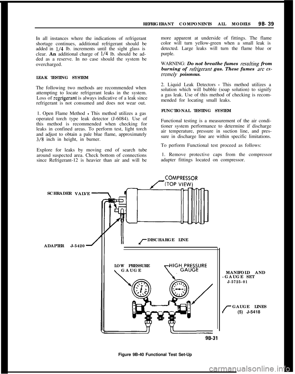
1. Remove protective caps from the compressor
adapter fittings located on compressor.
SCHRADER
ADAPTER J-5420
1II rDISCHARGE LINE
COMPRESSOR
VALVE
LOW PRESSURE
\ GAUGE\
HIGHGLR;B;URE
MANIFOLD AND
-GAUGE SET
J-5725-01
r
GAUGE LINES
(5) J-5418
9B-31
Figure 9B-40 Functional Test Set-Up
Page 549 of 625

98.40 1973 OPEL SERVICE MANUAL
2. Interconnect manifold and gage set (J-5725-01),
gage charging lines (J-5418) and gage adapters
(J-5420) to air conditioning system as shown in Figure
9B-40.3. Place transmission in “Park” for automatics and
in neutral for manuals. Apply hand brake.
4. Turn blower switch to the “Hi” position.
5. Turn temperature switch to “Max” position.
6. Run engine at 2000 RPM for ten (10) minutes with
car doors and windows closed and the hood up. Place
a high volume industrial type fan in front of radiator
if head pressure should exceed 250 psi and also at
high ambients to bring the pressures to within the
limits specified in the Functional Charts in Division
V.In the case of the Opel 1900 and the Manta, a ther-
mometer should be placed in a position to read the
temperature of the air discharging from the right-
hand A/C outlet. In case of the GT, a thermometer
should be placed in a position to read the tempera-
ture of the air discharging from the left-rear A/C
outlet.
HEATER-AIR CONDITIONER REFRIGERANT
CIRCUIT TROUBLE DIAGNOSIS GUIDE
Insufficient Cooling (Check Air Flow)
Normal Air Flow (Inspect system for visual defects.
Run functional tests.)
Discharge Air
- Normal Temp Check for air leaks
through dash, car body, windows, or from heater or
ventilators.
Discharge Air
- High Temp Check sight glass for
foaming and compressor clutch for engagement.
No Compressor Clutch Engagement Check connec-
tions at clutch switch, harness connectors, and check
clutch switch.
No Foaming Compare evaporator pressure to that
on functional test table.
Foaming System is probably low on refrigerant.
Check for leaks, repair, evacuate, and charge. If
foaming still occurs, check for restriction in refriger-
ant lines between condenser and receiver dehydrator.
Evaporator Pressure Normal Compare head pres-
sure to pressure on functional test table.
Evaporator Pressure Low Ice may be forming on
evaporator. Low volume of air discharging at A/C
outlet after system has been running above idle con-dition
,for approximately 15-30 min.utes. Discharging
air gradually elevating in temperature. Check expan-
sion valve. If valve isn’t permitting flow of liquid,
this will be indicated by a warm pipe out of the
evaporator. This may be caused by: 1) Clogged or
Plugged inlet screen in the expansion valve; 2)
Broken capillary line; or 3) Discharged temperature
bulb. If the valve is okay, the pipe out of the evapora-
tor will be cold.
Evaporator Pressure High Check the expansion
valve to determine if themobulb is making good con-
tact and is properly insulated. Operate engine at 2000
RPM with maximum air conditioning setting. If
evaporator pressure remains high, feel suction line.
If line feels frosty or extremely
(cold with relative
high ambient conditions, then partially cover the
condenser to obtain head pressures from 265 psi to
280 psi maximum. If evaporator pressure rises above
30 psi, change the expansion valve.
Also, check if compressor may be the cause due to
some internal or external mechanical trouble which
prevents reduction of pressure. Check for external
troubles, slipping belt, bad clutch and/or pulley, or
improper clutch engagement, before investigating
the compressor internally.
Head Pressure High Check for the following: Con-
denser air flow low, air in system, excessive refriger-
ant in system, restriction in condenser.Head.PressureLowRestriction in flow of refrigerant
to evaporator, or expansion valve plugged or defec-
tive.
Low Air Flow (Check blower operation and
evaporator. Check operation of controls.)
Ice BIocking Evaporator Run functional test. If
evaporator pressure is low, ice may form on evapora-
tor and reduce air flow.
Evaporator Pressure Low Ice may be forming on
evaporator. Low volume of air discharging at A/C
outlet after system has been running above idle con-
dition for approximately 15-30 minutes. Discharging
air gradually elevating in temperature. Check expan-
sion valve. If valve isn’t permitting flow of liquid,
this will be indicated by a warm pipe out of the
evaporator. This may be caused by: 1) Clogged or
plugged inlet screen in the expansion valve; 2)
Broken capillary line, or 3) Discharged temperature
bulb. If the valve is okay, the pipe out of the evapora-
tor will be cold.BlowerNot OperatingCheck for the following: Fuse
blown, blower switch defective, wire broken or loose
connection, poor ground connection, or blower mo-
tor defective.
Page 574 of 625
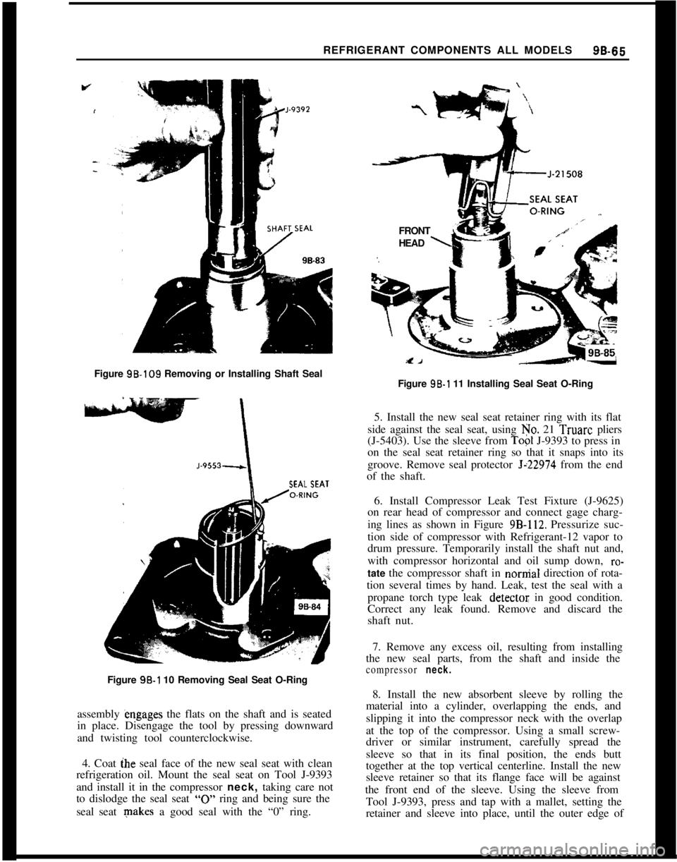
REFRIGERANT COMPONENTS ALL MODELS96-66Figure 98.109 Removing or Installing Shaft Seal
SEAL SEAT
-Figure 98-l 10 Removing Seal Seat O-Ring
assembly engages the flats on the shaft and is seated
in place. Disengage the tool by pressing downward
and twisting tool counterclockwise.
4. Coat ihe seal face of the new seal seat with clean
refrigeration oil. Mount the seal seat on Tool J-9393
and install it in the compressor neck, taking care not
to dislodge the seal seat
“0” ring and being sure the
seal seat makes a good seal with the “0” ring.FRONT
L’HEAD
\Figure 96-l 11 Installing Seal Seat O-Ring
5. Install the new seal seat retainer ring with its flat
side against the seal seat, using No. 21 Truarc pliers
(J-5403). Use the sleeve from
Top1 J-9393 to press in
on the seal seat retainer ring so that it snaps into its
groove. Remove seal protector
Jz22974 from the end
of the shaft.
6. Install Compressor Leak Test Fixture (J-9625)
on rear head of compressor and connect gage charg-
ing lines as shown in Figure
9B-112. Pressurize suc-
tion side of compressor with Refrigerant-12 vapor to
drum pressure. Temporarily install the shaft nut and,
with compressor horizontal and oil sump down,
ro-tate the compressor shaft in nornial direction of rota-
tion several times by hand. Leak, test the seal with a
propane torch type leak
detectot; in good condition.
Correct any leak found. Remove and discard the
shaft nut.
7. Remove any excess oil, resulting from installing
the new seal parts, from the shaft and inside the
compressor neck.8. Install the new absorbent sleeve by rolling the
material into a cylinder, overlapping the ends, and
slipping it into the compressor neck with the overlap
at the top of the compressor. Using a small screw-
driver or similar instrument, carefully spread the
sleeve so that in its final position, the ends butt
together at the top vertical centerline. Install the new
sleeve retainer so that its flange face will be against
the front end of the sleeve. Using the sleeve from
Tool J-9393, press and tap with a mallet, setting the
retainer and sleeve into place, until the outer edge of
Page 591 of 625
r98-82 1973 OPEL SERVICE MANUAL
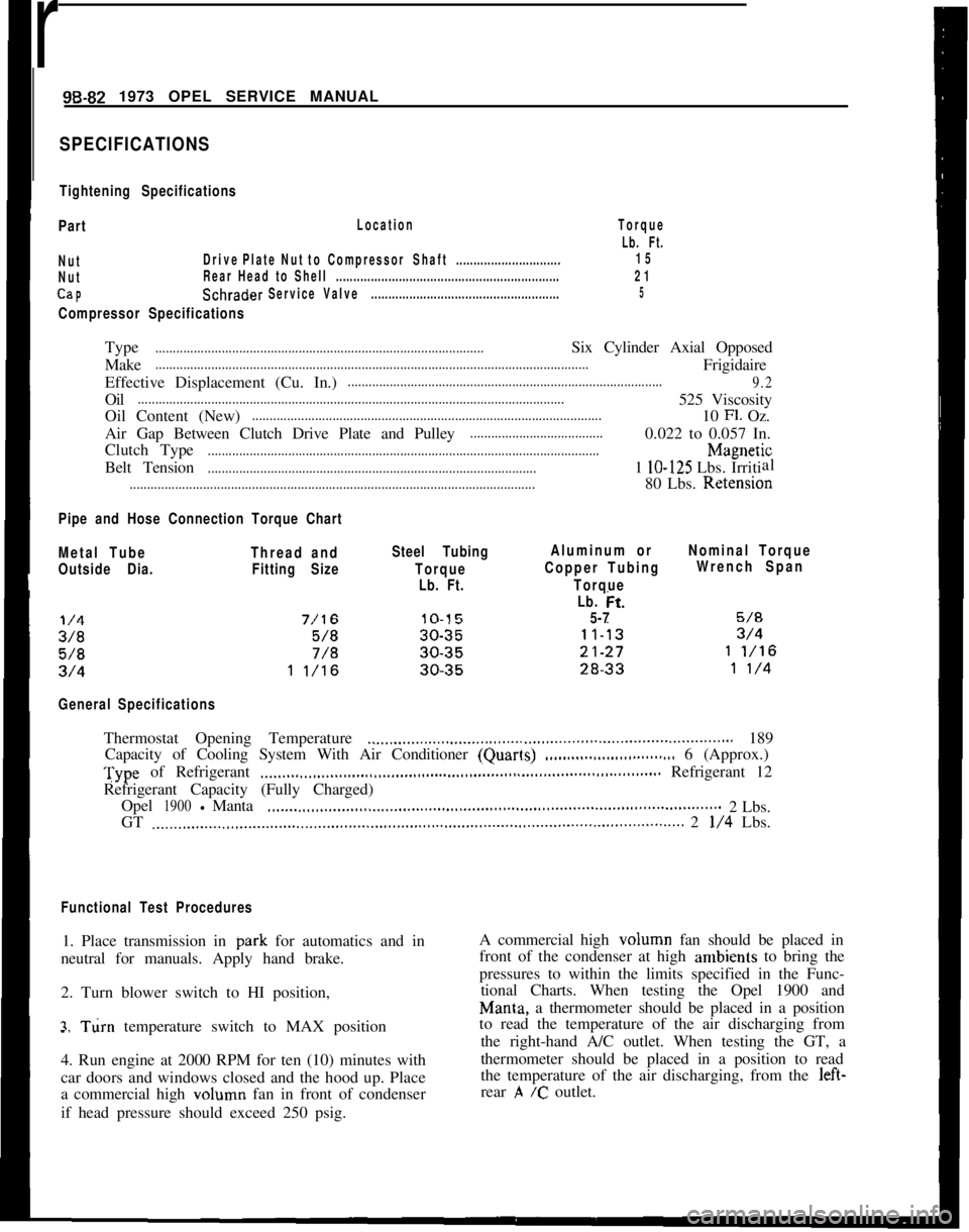
SPECIFICATIONS
Tightening Specifications
Part
Location
NutDrivePlateNut toCompressorShaft..............................
NutRear Head to Shell................................................................
CaPSchraderServiceValve......................................................
Compressor Specifications
Torque
Lb. Ft.
15
21
5Type
..............................................................................................Six Cylinder Axial Opposed
Make
............................................................................................................................Frigidaire
Effective Displacement (Cu. In.)
..........................................................................................
9.2Oil
..........................................................................................................................525 Viscosity
Oil Content (New)
....................................................................................................10 Fl. Oz.
Air Gap Between Clutch Drive Plate and Pulley
......................................0.022 to 0.057 In.
Clutch Type
................................................................................................................h4agnetic
Belt Tension
..............................................................................................1 lo-125 Lbs. Irritial
....................................................................................................................80 Lbs. Retension
Pipe and Hose Connection Torque Chart
Metal TubeThread andSteel TubingAluminum orNominal Torque
I
Outside Dia.Fitting SizeTorqueCopper TubingWrench Span
Lb. Ft.Torque
Lb. tit.
5-7
General SpecificationsThermostat Opening Temperature
.._.....,,,...__....,,.............................................................. 189
Capacity of Cooling System With Air Conditioner (Quarls)
.,,..___....___............... 6 (Approx.)Type of Refrigerant
.___,,,._...,.,,,.__.....,,,.......,,,,.......,,,...................,,,......,,,............ Refrigerant 12
Refrigerant Capacity (Fully Charged)
Opel
1900-Manta,,._....,,,,._...._.,,,,.......,,,........,,............................................................2 Lbs.
GT
,..__..,..,..__..,,,.......,,,,.......,,,........,,,.,......,,,,,......,,.,,........,,.......,,..........,,............... 2 l/4 Lbs.
Functional Test Procedures1. Place transmission in park for automatics and in
neutral for manuals. Apply hand brake.
2. Turn blower switch to HI position,
3. Turn temperature switch to MAX position-.
4. Run engine at 2000 RPM for ten (10) minutes with
car doors and windows closed and the hood up. Place
a commercial high volumn fan in front of condenser
if head pressure should exceed 250 psig.A commercial high volumn fan should be placed in
front of the condenser at high ambients to bring the
pressures to within the limits specified in the Func-
tional Charts. When testing the Opel 1900 and
Man& a thermometer should be placed in a position
to read the temperature of the air discharging from
the right-hand A/C outlet. When testing the GT, a
thermometer should be placed in a position to read
the temperature of the air discharging, from the left-
rear
,A /c outlet.