trunk OPEL GT-R 1973 Service Manual
[x] Cancel search | Manufacturer: OPEL, Model Year: 1973, Model line: GT-R, Model: OPEL GT-R 1973Pages: 625, PDF Size: 17.22 MB
Page 10 of 625

GENERAL INt=ORMATION OA-1
GENERAL INFORMATIONKEYS AND LOCKSEvery key has a number engraved on one side which
identities the key blank manufacturer. On the oppo-
site side of GT keys, is a removable adhesive foil on
which, the profile and cutting code letters and num-
bers are imprinted. Attached to the protective key
cover of Opel
1900 and Manta keys, is a tab on which
the profile and cutting code letters and numbers are
imprinted. Record the key cutting code letters and
numbers before the adhesive foil or plastic tabs are
discarded as this information is necessary to obtain
replacement keys.
In the event of lost keys and code records, one or
more locks may be removed to obtain the code num-
bers. The codes are stamped on the trunk and igni-
tion lock cylinders and on the door lock plunger
shaft. If a lock cylinder is damaged, it must be re-
placed. This then means that the owner will have an
additional key.REMOVE ANDDOOR &
IGNIKEY CODELOCK. OPELIGNITION
LOCKGAS CAP LOCKGTGT
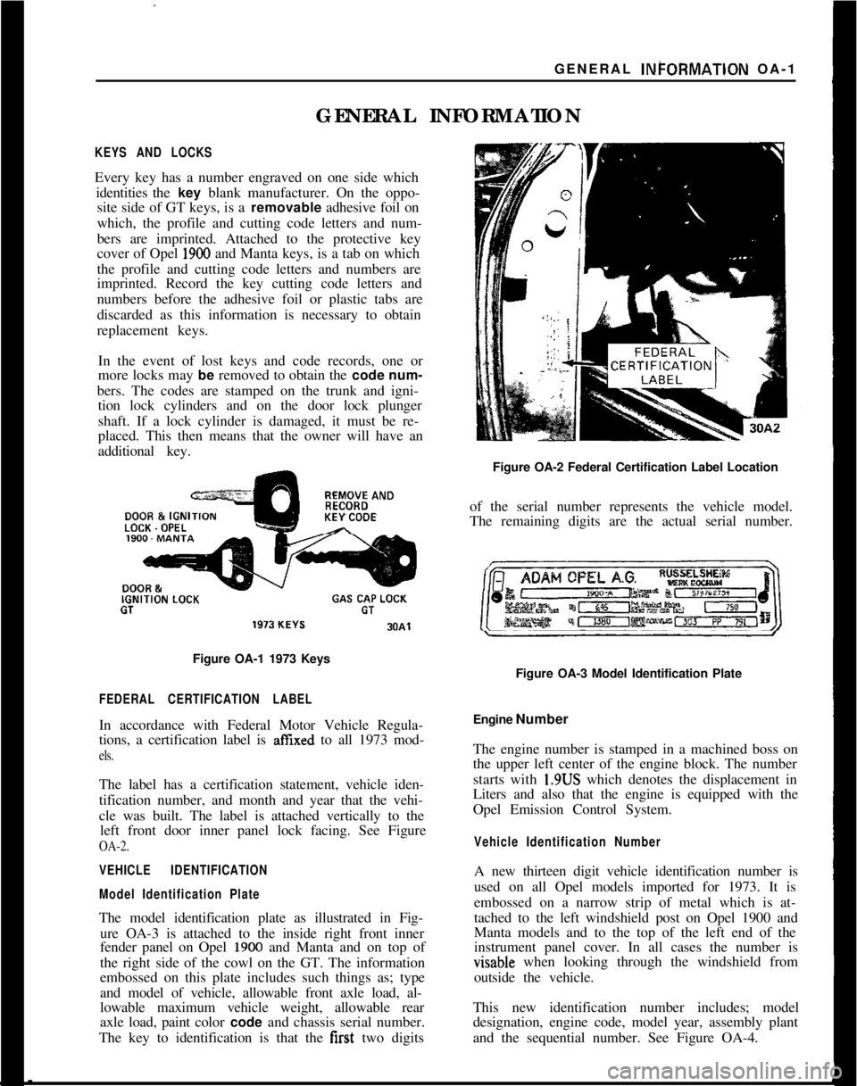
Figure OA-1 1973 Keys
FEDERAL CERTIFICATION LABELIn accordance with Federal Motor Vehicle Regula-
tions, a certification label is
affIxed to all 1973 mod-
els.The label has a certification statement, vehicle iden-
tification number, and month and year that the vehi-
cle was built. The label is attached vertically to the
left front door inner panel lock facing. See Figure
OA-2.
VEHICLE IDENTIFICATION
Model Identification PlateThe model identification plate as illustrated in Fig-
ure OA-3 is attached to the inside right front inner
fender panel on Opel
1900 and Manta and on top of
the right side of the cowl on the GT. The information
embossed on this plate includes such things as; type
and model of vehicle, allowable front axle load, al-
lowable maximum vehicle weight, allowable rear
axle load, paint color code and chassis serial number.
The key to identification is that the first two digitsFigure OA-2 Federal Certification Label Location
of the serial number represents the vehicle model.
The remaining digits are the actual serial number.
Figure OA-3 Model Identification Plate
Engine Number
The engine number is stamped in a machined boss on
the upper left center of the engine block. The number
starts with 1.9US which denotes the displacement in
Liters and also that the engine is equipped with the
Opel Emission Control System.
Vehicle Identification NumberA new thirteen digit vehicle identification number is
used on all Opel models imported for 1973. It is
embossed on a narrow strip of metal which is at-
tached to the left windshield post on Opel 1900 and
Manta models and to the top of the left end of the
instrument panel cover. In all cases the number isvisable when looking through the windshield from
outside the vehicle.
This new identification number includes; model
designation, engine code, model year, assembly plant
and the sequential number. See Figure OA-4.
Page 18 of 625

LUBRICATION AND MAINTENANCE OC-9
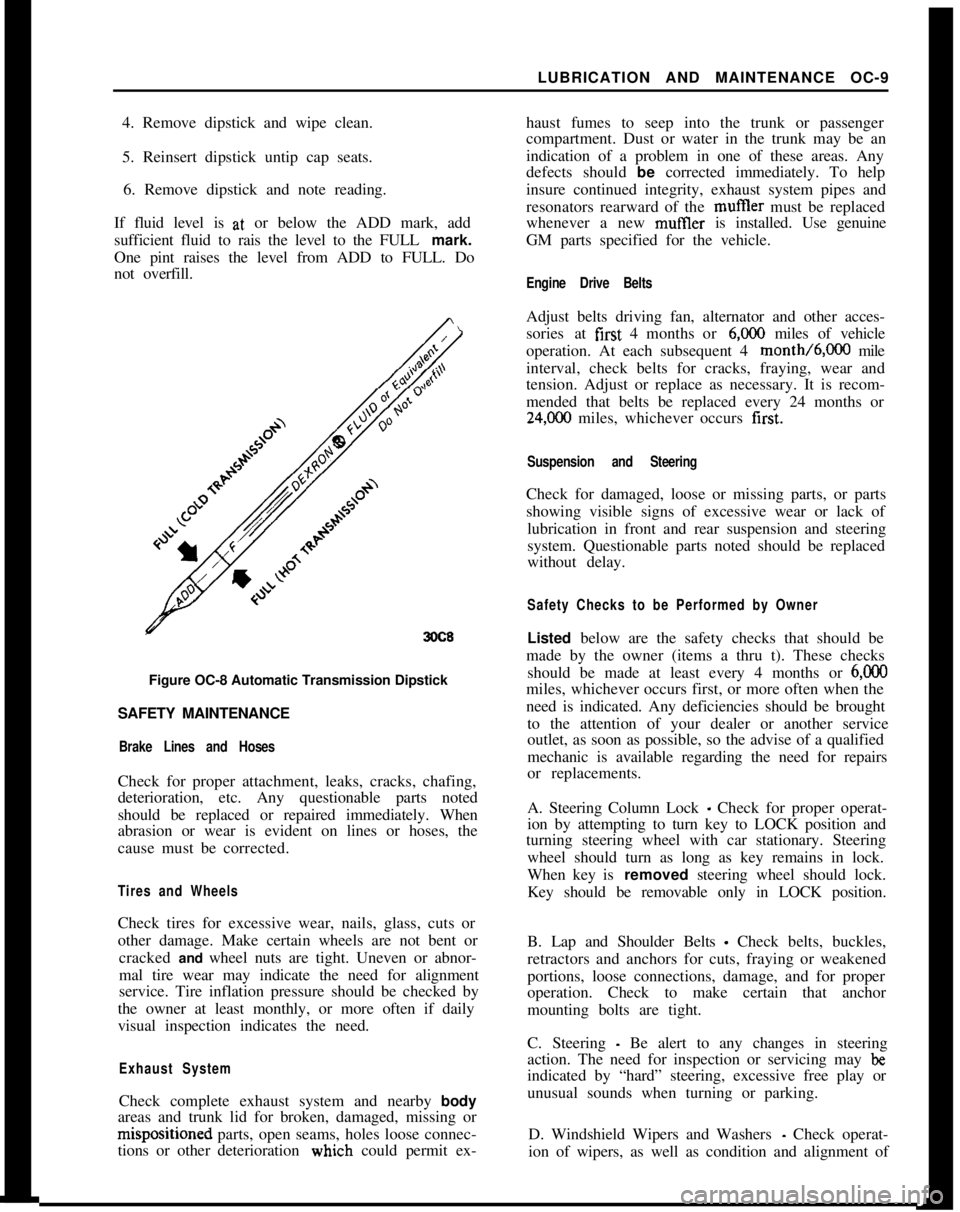
4. Remove dipstick and wipe clean.
5. Reinsert dipstick untip cap seats.
6. Remove dipstick and note reading.
If fluid level is at, or below the ADD mark, add
sufficient fluid to rais the level to the FULL mark.
One pint raises the level from ADD to FULL. Do
not overfill.
3OC8Figure OC-8 Automatic Transmission Dipstick
SAFETY MAINTENANCE
Brake Lines and HosesCheck for proper attachment, leaks, cracks, chafing,
deterioration, etc. Any questionable parts noted
should be replaced or repaired immediately. When
abrasion or wear is evident on lines or hoses, the
cause must be corrected.
Tires and WheelsCheck tires for excessive wear, nails, glass, cuts or
other damage. Make certain wheels are not bent or
cracked and wheel nuts are tight. Uneven or abnor-
mal tire wear may indicate the need for alignment
service. Tire inflation pressure should be checked by
the owner at least monthly, or more often if daily
visual inspection indicates the need.
Exhaust SystemCheck complete exhaust system and nearby body
areas and trunk lid for broken, damaged, missing orm&positioned parts, open seams, holes loose connec-
tions or other deterioration wiuch could permit ex-haust fumes to seep into the trunk or passenger
compartment. Dust or water in the trunk may be an
indication of a problem in one of these areas. Any
defects should be corrected immediately. To help
insure continued integrity, exhaust system pipes and
resonators rearward of the muftler must be replaced
whenever a new mufIler is installed. Use genuine
GM parts specified for the vehicle.
Engine Drive BeltsAdjust belts driving fan, alternator and other acces-
sories at first 4 months or
6,ooO miles of vehicle
operation. At each subsequent 4 month/6,000 mile
interval, check belts for cracks, fraying, wear and
tension. Adjust or replace as necessary. It is recom-
mended that belts be replaced every 24 months or
24,C00 miles, whichever occurs first.
Suspension and SteeringCheck for damaged, loose or missing parts, or parts
showing visible signs of excessive wear or lack of
lubrication in front and rear suspension and steering
system. Questionable parts noted should be replaced
without delay.
Safety Checks to be Performed by OwnerListed below are the safety checks that should be
made by the owner (items a thru t). These checks
should be made at least every 4 months or
6,ooOmiles, whichever occurs first, or more often when the
need is indicated. Any deficiencies should be brought
to the attention of your dealer or another service
outlet, as soon as possible, so the advise of a qualified
mechanic is available regarding the need for repairs
or replacements.
A. Steering Column Lock
_ Check for proper operat-
ion by attempting to turn key to LOCK position and
turning steering wheel with car stationary. Steering
wheel should turn as long as key remains in lock.
When key is removed steering wheel should lock.
Key should be removable only in LOCK position.
B. Lap and Shoulder Belts
- Check belts, buckles,
retractors and anchors for cuts, fraying or weakened
portions, loose connections, damage, and for proper
operation. Check to make certain that anchor
mounting bolts are tight.
C. Steering
- Be alert to any changes in steering
action. The need for inspection or servicing may
beindicated by “hard” steering, excessive free play or
unusual sounds when turning or parking.
D. Windshield Wipers and Washers
- Check operat-
ion of wipers, as well as condition and alignment of
Page 77 of 625

:lG- 56 1973 OPEL SERVICE MANUAL
I
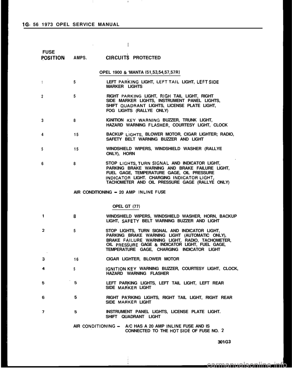
FUSEqOSlTlON
1
2
3
4
5
6AMPS.
5
5
8
15
15
8ClRClJlT$ PROTECTED
OPEL 1900
& ‘MANTA (51,53,54,57,57R)
LEFT PARkING LIGHT,
LEFTTAIL LIGHT, LEFTSIDE
MARKER LIGHTS
RIGHT PApKING LIGHT, RIGH TAIL LIGHT, RIGHT
SIDE MARKER LIGHTS, INSTRUMENT PANEL LIGHTS,
SHIFT GUADRANT LIGHTS, LICENSE PLATE LIGHT,
FOG LIGHTS (RALLYE ONLY)
IGNITION IKEY
WARNIN BUZZER, TRUNK LIGHT,
HAZARD WARNING FLA,SHER, COURTESY LIGHT, CLOCK
BACKUP L’IGHTS, BLOWER MOTOR, CIGAR LIGHTER; RADIO,
SAFETY BELT WARNING BUZZER AND LIGHT
WINDSHIELD WIPERS, WINDSHIELD WASHER (RALLYE
ONLY), HORN
STOP LIGtiTS,TURN
SlGsNAL AND INDICATOR LIGHT,
PARKING BRAKE WARNING AND BRAKE FAILURE LIGHT,
FUEL GAGE, TEMPERATURE GAGE, OIL PRESSUREINDICATGR LIGHT. CHARGING INDICATOR~LIGHT,
TACHOMETER AND OIL PRESSURE GAGE (RALLYE ONLY)
AIR CONDITIONING
- 20 AMP INLINE F:USE
8
5
16
5OPEL GT
(77)WINDSHIELD WIPERS, WINDSHIELD WASHER, HORN, BACKUP
LIGHT, SP;FETY BELT WARNING BUZZER AND LIGHT
STOP LIGHTS, TURN SIGNAL AND INDICATOR LIGHT,
PARKING BRAKE WARNING LIGHT (AUTOMATIC ONLY),
BRAKE FAILURE WARNING LIGHT, RADIO, TACHOMETER,
OIL PRESiURE GAGE
& INDICATOR LIGHT, FUEL GAGE,
TEMPERATURE GAGE, CHARGING INDICATOR LIGHT
CIGAR LIGHTER, BLOWER MOTORIGNITION~KEY WARNING BUZZER, COURTESY LIGHT, CLOCK,
HAZARD WARNING FLASHER
LEFT PARKING LIGHTS, LEFT TAIL LIGHT, LEFT REAR
SIDE MAdKER LIGHT
RIGHT PA’RKING LIGHTS, RIGHT TAIL LIGHT, RIGHT REAR
SIDE MAdKER LIGHT
INSTRUMENT PANEL LIGHTS, LICENSE PLATE LIGHT.
SHIFT QUADRANT LIGHT
AIR CON,DlTlONlNG
-A/C HAS A 20 AMP INLINE FUSE AND IS
CONNECTED TO THE HOTSIDE OF FUSE NO. 23OlG3
Page 105 of 625

r
2UREDp
IM
BRNIWHI
BUZZER
3 CLOSED POSlTlONl
/-
14 RED - TO STEERING
COLUMN CONN.
20 RED
12 RED FROM BATTERY--18 GRAY--12 RED
-I
J
DOME LIGHT
&SWITCH1
1
.,_ &,,,.~~
STEER I NG
COLUMN
CONNECTORTRUNK LIGHT?&SWITCH
IGNITION
SWITCH‘\BUZZER SWITCH(HELD CLOSED WITH
KEY IN “OFF” & “LOCK”POSITION1
3OlJll
Page 148 of 625

ROOF AND SUN ROOFZF-25ConditionCallseCorrectionSun roof lifts up on one
side only.Lifter wedge welded to under-
Remove sun roof panel and bend
side of sun roof panel doeslifter wedge so that it squarely hits
not run up ramp welded inramp. The only adjustment for
center of sun roof track.the ramp is the angle of the
rear portion. This should be
adjusted so that the wedge smoothly
rides up the ramp.
Transporter cable or drive
pinion damaged.If the transporter cable is worn
or damaged, replace both
cables. If drive pinion worn or
damaged, replace drive pinion and
also both transporter cables.
Sun roof scrapes on car roof
when closing sun roof.Lifters do not lie flat.Close sun roof, slide sun roof
frame to the rear and open and close
sun roof slightly noting operation
of lifters. Rework if necessary,plastjc lifter cushion with tile
to permit lifter to lie flat.
Sparingly lubricate lifter guide.
Sun roof frame becomes
detached.Attaching clips have lost
elasticity.Install new clips
Water enters car interior.
Water drain hoses blocked.
Bent water drain hoses
Rear water drain hoses have
been pulled out of rubber
grommets.
Velvet strips on front and
rear of sun roof do not seal
properly.Clean hoses with compressed air
or a flexible steel cable.
NOTE: To clear rear water
drain hoses, the sun roof panel
and frame must be removed.
Blowing out of rear drain hoses
from trunk compartment hose end
is not recommended due to
possibility of soiling car
interior.
Attempt to straighten drain
hoses by working a suitable
tube or cable through hose.
Replace hose if above corrective
action is not satisfactory.
Apply a small amount of rubber
cement to rear water drain
hoses and reinsert into rubber
grommet located in luggage
compartment floor panel.
Check sun roof for correct
height adjustment. If height
adjustment is correct, but a
tight seal does not exist,
relocate velvet strip upward
for better seal, or replace
velvet strip.
Page 158 of 625

SEATS, INTERIOR TRIM AND HEADLININGZG-35
2. Push off side panel trim pad. Trim pad is held in
position by a retaining button.
REMOVAL AND INSTALLATIONOF HEADLINING
Removal
1. Disconnect battery.
2. Lift out rear seat cushion (sedans only).
3. From trunk area, loosen tabs holding cardboard
against rear seat cross brace and lift out cardboard
(sedans only).
4. Pry up two tabs holding lower portion of rear seat
back in position, swing back of seat forward and lift
out (sedans only).
5. From trunk area pry out parcel shelf plastic retain-
ers and lift out parcel shelf (sedans only).
6. Remove rear-view mirror, sun visors, interior
lamp, assist straps and coat hooks. Remove front and
rear windows on all but Wagon Models. On Wagons,
remove the front window and the quarter windows.
7. Work door opening pinchweld finishing strip
away from pinchweld as far as necessary to expose
edge of headlining.
8. Start at: left or right windshield pillar and pry
headlining loose.
9. Roll back headlining to expose metal tabs securing
headlining listing wire to roof and unhook headhn-
ing front listing wire from metal tabs using a blunt
edge tool.
10. Pull loose the edges of headlining cemented to
door openings, rear quarter window openings, rear
quarter pillar and from under rear window rubber
channel. On rear quarter pillars, slightly bend down
cardboard of rear quarter trim pad to facilitate re-
moval. During removal, special care should be taken
not to tear headlining at seams.
11. After edges of headlining have been pulled loose,
tilt remaining listing wires with headlining forward
or rearward and pull listing wires free from side roof
rails. Lift out headlining and listing wires.
Installation1. Check secureness of noise insulation pad on inside
of roof panel and recement as necessary using asphalt
cement. If headlining is to be replaced, insert listing
wires into headlining according to their markings.
Progressing from the front listing wire to the rear
wire, the left ends of the wires are color coded as
follows:1st listing wire
- No marking, wire is thinner than
other wires
2nd listing wire
- Red
3rd listing wire
- Blue
4th listing wire
_ Green
5th listing wire
- Brown
6th listing wire
- White
2. Install 1st listing wire ends into retainer slots in-
side roof rails and hook listing wire into six metal
tabs above windshield. Lightly bend tabs with a ham-
mer as shown in Figure
2G-8.
HEAOLlN’lNdA-----
26-8Figure
2G-8 Headlining With 1st Listing Wire Hooked
Onto Metal Tabs
LISTINGWIRE
SECTIOND-D
4 26-9Figure 2G-9 2nd and 5th Listing Wire Attachment
Page 160 of 625

SEATS, INTERIOR TRIM AND HEADLINING20.378. If wagon, install front window and quarter win-
dows. It other than wagon, install front and rear
windows.9. Install coat hooks, assist straps, interior lamp, sun
visors, and rear view mirror.
10. Install parcel shelf and plastic retainers (sedans
only).
11. Install rear seat back into position and bend over
tabs holding lower portion of seat back (sedans only).
12. In trunk area instail cardboard against rear seat,
cross brace, and bend over tabs (sedans only).
13. Install rear seat cushion (sedans only).
14. Connect battery.REMOVAL AND INSTALLATION OF REAR SIDE
PANEL TRIM PAD
1, Unscrew shield on lock pillar. See Figure 2G- 11.
2. Pull off sealing strip on lock pillar and rear quarter
window. See Figure 2G- 12.
3. Remove ash tray.
4. Remove rear seat and push retaining button out of
trim pad. See Figure
2G-13.5. Pull out trim pad towards the front.
6. Prior to installation, press together sealing strip
ends to obtain a tight seat.
Page 165 of 625

FLVTRlJNK PLAT
DRAW BAR16x1-1/2 -DRAW‘ BAR EXTENSION-%GSAFETY CHAIN PLATE6INSTALLATION INSTRUCTIONS
1971
- 72 - 73 OPEL 1900 SERIES S/W
GROUP NO. 7.068
REMOVE LICENSE PLATE
STEP 1. ASSEMBLE HITCH AS ILLUSTRATED. HOLD
HITCH IS POSITION WITH FLOOR PLATE RESTING
AGAINST THE CROSS FRAME IN FRONT OF GAS TANK.
CENTER DRAW BAR SUPPORT ON THE REAR BODY
PANEL, RAISE UNTIL LEVEL.
STEP 2.MARK AND DRILL TWO
7116” HOLES IN REAR
BODY PANEL AND ATTACH AS SHOWN.
STEP 3.DRILL TWO
112” HOLES IN CROSS FRAME IN
FRONT OF THE GAS TANK AND CONTINUE DRILLING UP
THROUGH THE INNER FLOOR. NOTE: HOLD DRILL
VERTICAL WHILE DRILLING THROUGH THE INNER FLOOR.
ENLARGE BOTTOM HOLE SLIGHTLY TO ACCEPT SPACER.
STEP 4. ATTACH TRUNK PLATE AS ILLUSTRATED. PLACE
THE FLOOR PLATES ON THE 2
l/2” CARRIAGE BOLTS
AND INSERTS THROUGH THE OPENINGS
iN THE BACK OF
THE TRUNK WELL.INSERT SPACERS AS SHOWN AND
COMPLETE INSTALLATION.
REPLACE LICENSE PLATE.
TIGHTEN ALL
112” NUTS TO A MAXIMUM TORQUE OF
60 FOOT LBS. AND 7/16” NUTS TO A MAXIMUM OF
45 FOOT LBS.
INSTALL BALL USING A MAXIMUM TORQUE OF 150
FOOT LBS.
MAXIMUM GROSS WEIGHT 100 LBS
MAXIMUM TONGUE WEIGHT 100 LBS.
MOST STATES PROHIBIT OBSTRUCTION OF LICENSE
PLATES, BALL SHOULD BE REMOVED WHEN NOT IN
USE IF IT OBSTRUCTS A CLEAR VIEW.
ZH-9Figure
ZH-9 Opel 1900 Wagon Trailer Hitch Installation