warning light OPEL GT-R 1973 Service Manual
[x] Cancel search | Manufacturer: OPEL, Model Year: 1973, Model line: GT-R, Model: OPEL GT-R 1973Pages: 625, PDF Size: 17.22 MB
Page 19 of 625
CC-10 1973 OPEL SERVICE MANUAL
wiper blades. Check amount and direction of fluid
sprayed by washers during use.,
E. Defrosters - Check performance by moving con-
trols to “DEF” and noting
am$nmt of air directed
against the windshield.
I
F. Wheel Alignment and
Balabce - In addition to
abnormal tire wear, the need fbr wheel alignment
service may be indicated by a pull to the right or
!eftwhen driving on a straight and level road. The need
for wheel balancing is usually
iddicated by a vibra-
tion of the steering wheel or
se;+ tihile driving at
normal highway speeds.I
IG. Brakes
- Be alert to illumiriation of the brake
warning light or changes in braking action,
SUCK as
repeated pulling to one side, unusual sounds when
braking or increased brake pedal travel. Any of thesecould indicate the need for
brakk system inspection
and/or service.
H. Parking Brake and Transmission “PARK”
Mechanism
- Check parking brake holding ability by
parking on a fairly steep hill and restraining the vehi-
cle with the parking brake only.
eon cars with auto-
matic transmissions, check the holding ability of the
“PARK” mechanism by releasing all brakes after
the transmission selector lever hak been placed in the“P” position.
I. Glass
- Check for broken, scrritched, dirty or da-
maged glass on vehicle that
coulld obscure vision’or
become an injury hazard.
J. Lights and Buzzers
- Check all instrument panel
illuminating and warning lights,’ seat belt reminder
light and buzzer, ignition key
b&er, interior lights,
license plate lights, side marker! lights, headlamps,
parking lamps, tail lamps, brake lights, turn signals,
backup lamps, and hazard warding flashers. Have
someone observe operation of
&ach exterior light
while you activate the controls: The operation of
instrument panel warning lights is covered in the
“Starting and Operating“ section of your
Own&%
Manual.K. Transmission Shift Indicator
‘- Check to be sure
automatic transmission shift
indiCator accurately i”-
dicates the shift position selected.
I
CAUTION: Before making thk check below,I
be sure to have a clear dist&e ahead and:
behind the car, set the parking brake and
firmly apply the foot brake.
Do not depress
accelerator pedal. Be prepared to
turn off ’
ignition switch
immediat+y if engine
should start.L. Starter Safety Switch (Automatic Transmissibn
Cars)
- Check starter safety switch by placing the
transmission in each of the driving gears while
at-tempting to start the engine. The starter should oper-ate only in the Park (“P”) or Neutral (“N”)
positions.
M. Horn
- Blow the horn occasionally to be sure thatit works. (Ignition switch must be in the “ON” posi-
tion.)
N. Seat Back Latches
- Check to see that seat back
latches are holding by pulling forward on the top of
each folding seat back.
0. Rearview Mirrors and Sun Visors
- Check that
friction joints are properly adjusted so mirrors and
sun visors stay in the selected position.
P. Door Latches
- Check for positive closing, latch-
ing and locking.
Q. Hood Latches - Check to make sure hood closesfirmly by pressing on the hood at the latching point
after each closing. Check also for broken, damaged
or missing parts which might prevent secure latch-
ing.R. Fluid Leaks
- Check for fuel, water, oil or other
fluid leaks by observing the ground beneath the vehi-cle after it has been parked for a while. If gasoline
fumes or fluid are noticed at any time, the cause
should be determined and corrected without delay
because of the possibility of fire.
S. Exhaust System
- Be alert to any change in the
sound of the exhaust system or a smell of fumes
which may indicate a leak.
Head Restraints
- Check that no head restraint
components are missing, damaged or loose. (Does
not apply to GT Models).
Disc BrakesCheck brake pads and condition of rotors while
wheels are removed during tire rotation. (Note belowregarding more frequent checks also applies to disc
brakes.)
Parking and Drum BrakesCheck drum
brake linings and other internal brake
components at each wheel (drums, wheel cylinders,
etc.). Parking brake adjustment also should be
checked whenever drum brake linings are checked.
NOTE: More frequent checks should be
made if driving conditions a.nd habits result
in frequent brake application. When brakes
require relining, it is recommended thatyou use those genuine General Motors
parts specified for your car,and Delco fluid
as required.
Page 26 of 625
BATTERY AND CABLES - ALL MODELSlA- 5
and terminal connections should not exceed 2/10
volt.
5. Connedt voltmeter positive lead to ground on en-
gine.
At&h prod to voltmeter negative lead and
apply prod to center of battery negative post. Volt-
age drop across the battery ground cable and termi-
nal conne$tions should not exceed 2/10 volt at
200amps.
6. A reading in excess of 2/10 volt when testing
either battery cable indicates excessive resistance in
cable or cpnnections. Clean and tighten cable or con-
nections. Clean and tighten cable terminals
(sub-para. c, below) and recheck for voltage drop. If volt-
age drop Still exceeds 2/10 volt, replace cable with a
genuine Buick-Opel cable to insure ample capacity.
Undercharge Failure of BatteryThe most frequent trouble experienced with storage
batteries is failure to maintain a state of charge suffi-
cient to crank the engine and also furnish current to
the ignitibn system, lights and accessories. Failure to
maintain a proper state of charge may be due to one
or more of the following conditions:
1.
Opertiting Conditions. When determining cause
of premature failure of a battery, consideration must
be given /to the conditions under which the car is
operated.,
In very low temperatures the capacity of a storage
battery
ii considerably reduced and the energy re-
quired f& cranking the. engine is considerably in-
creased. :
Frequent starting, particularly in cold weather,
ac-compani
place in the limited running time. This condition is
aggravated by night driving when lights are turned
on, or by operation of an air conditioner in heavy
traffic.
When thk car is operated under these conditions,adjusting,the voltage regulator to the high limit may
allow enough increase to keep the battery at a safe
state of charge. If the high limit setting does not
maintain a safe state of charge, an occasional booster
charge should be given to the battery.
2. Low charging Rate. In case of premature battery
failure, tbe charging rate of alternator should always
be checked and adjusted if below specifications.
3.
Zntemd Condition The internal condition of the
battery niay be such that it cannot hold a chargesatisfactoiily. Check electrolyte level and test the
battery using the 421 Battery Test.
Overcharge Failure of BatteryA common cause of battery failure is overcharging,
that is, continued input of excessive charging current
after the battery has reached a fully charged condi-
tion.
One evidence that battery is being overcharged is the
need for frequent addition of water to the battery in
order to maintain the electrolyte level above the tops
of the battery separators, since overcharging causes
rapid water loss. When this becomes evident, the
charging rate of alternator should be immediately
checked, as well as the voltage regulator, and ad-
justed to avoid internal damage to battery.
ADJUSTMENTS AND MINOR SERVICEPERIODIC BATTERY INSPECTION AND SERVICE
The battery requires very little attention, but peri-
odic inspection is essential to secure the maximum
efficiency and life. The following services are essen-
tial to maintain the battery at maximum efficiency.
WARNING: Never expose battery to open flame or
electric spark
- battery action generates hydrogen gas
which is flammable and explosive. Do not allow bat-
tery fluid to contact skin, eyes, fabrics or painted
surfaces
- fluidis a sulfuric acid solution which could
cause serious personal injury or property damage.
Wear eye protection when working with battery.
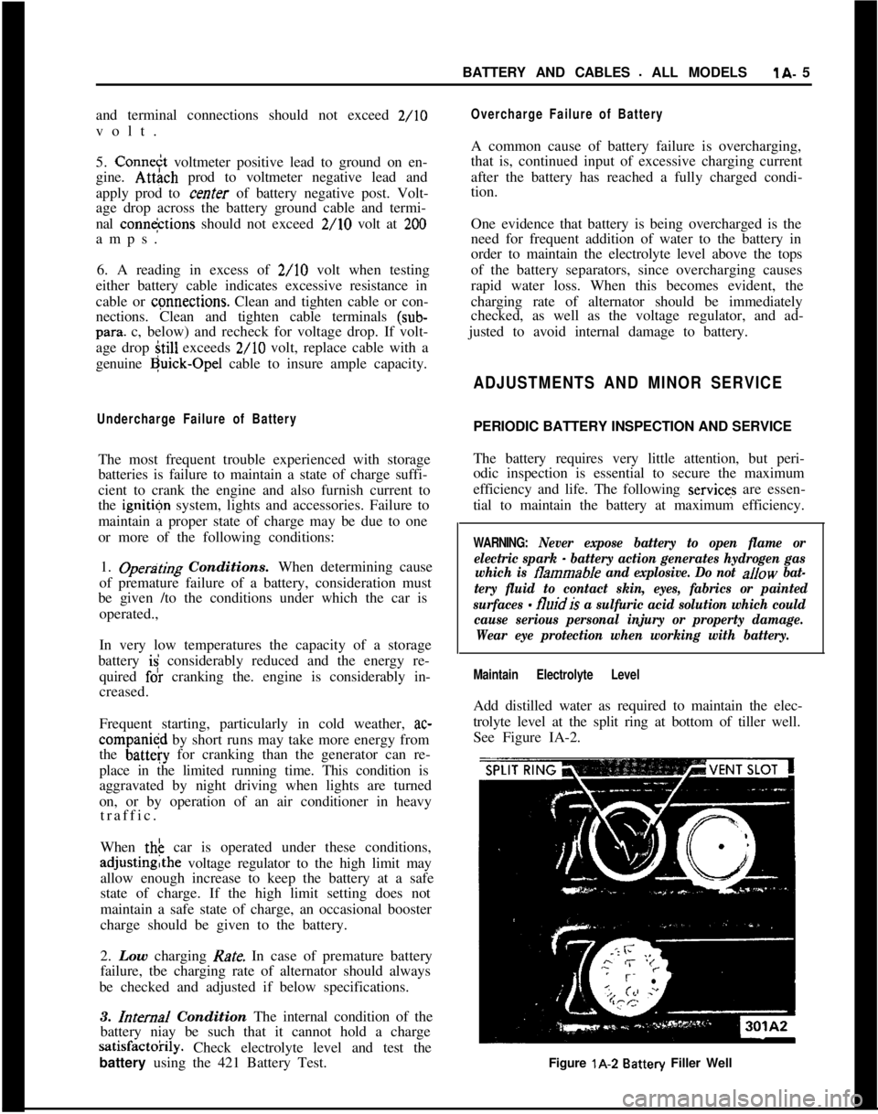
Maintain Electrolyte LevelAdd distilled water as required to maintain the elec-
trolyte level at the split ring at bottom of tiller well.
See Figure IA-2.
Figure lA-2
Battery Filler Well
Page 75 of 625

lG- 54 1973 OPEL SERVICE’ MANtiAL/SIGNAL SYSTEMSCdNTENTS
9Subject
DESCRIPTION AND OPERAT!ON:
Directional Signal Lever
. . . . . . . . . . . . . . . . . . . . . . . . . . . . . . . . . . . . . . . . . . . . . . . . . .
Horn. . . . . . . . . . . . . . . . . . . . . . . . . . . . . . . . . . . . . . . . . . . . . . . . . . . . . . . . . . . . . . . . . . . . . . . . . . . . . . . . . . . . . . . .HazardWarning
Flasher. . . . . . . . . . . . . . . . . . . . . . . . . . . . . . . . . . . . . . . . . . . . . . . .BrakeSystemWarningLight
. . . . . . . . . . . . . . . . . . . . . . . . . . . . . . . . . . . . . . . .DIAGNOSIS:
SignalSystem,.......................
i . . . . . . . . . . . . . . . . . . . . . . . . . . . . . . . . . . . . . . . . . . . . .MAINTENANCE AND ADJUS,TMENTS:
MAJOR REPAIR:
Directional Signal Switch
:. . . . . . . . . . . . . . . . . . . . . . . . . . . . . . . . . . . . . . . . . . . . .
HornRemoval. . . . . . . . . . . . . . . . . . . . . . . . . . . . . . . . . . . . . . . . . . . . . . . . . . . . . . . . . . . . . . . . . . . . . .Removing Horn Contact
. . . . :.............................................
SPECIFICATIONS:
FuseChart. . . . . . I . . . . . . . . . . . . . . . . . . . . . . . . . . . . . . . . . . . . . . . . . . . . . . . . . . . . . . . . . . . . . . . . . . . . .Page No.
1 G-54
1 G-54
1 G-55
lG-55 _1 G-55
1 G-55
16-551 G-55
1 G-56
DESCRIPTION AND OPERATION
DIRECTIONAL SIGNAL LEVERThe direction signal switch lever is a multi- purpose
lever controlling direction signals, passing signal,
and high and low beams. See Figure
lG-1.301Gl
Figure lG-1 Directional Signal Position for Headlamp
OperationThe direction signal lever is provided with a
two-step mechanism for operation of headlight high and
low beams, and passing signal (not in New Jersey).
With headlights off, moving the lever repeatedly to-
wards steering wheel flashes headlights as a passing
signal. With headlights on, moving the lever repeat-
edly towards steering wheel up to first stop also
flashes passing signal regardless whether or not the
direcl:ion signals are switched on. When the lever is
moved up to the second stop, the headlights are
changed from high to low beam
dr vice versa. On all
Rallye cars, when switching from low to high beam
position, with the fog lamp instrument panel switch
“ON” and ignition switch in “RUN” position, the
fog lights are automatically
switChed off. Direction
signals work in the normal manner; pushing the lever
up for right turn signal and pulling the lever down
for left turn signal.
The horn button is located in the center part of the
steering wheel. The horn is actuated by pushing
down on the ends of both spokes on Opel 1900 andManta’s or on the center horn button on the Rallye.
The button is provided with a spring-loaded plunger.See Figure
lG-2.
Page 76 of 625
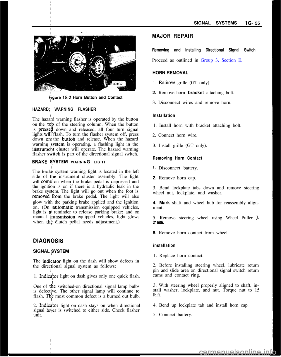
Tigure lG-2 Horn Button and Contact
HAZARD; WARNING FLASHER
The hazard warning flasher is operated by the button
on the
toi, of the steering column. When the button
is
press&@ down and released, all four turn signal
lights
WIU flash. To turn the flasher system off, press
down
oni the button and release. When the hazard
warning
hystem is operating, a flashing light in the
iristrumeht cluster will operate. The hazard warning
flasher
&itch is part of the directional signal switch.
BRAKE $YSTEM WARNING LIGHT
The brak; system warning light is located in the left
side of
tpe instrument cluster assembly. The light
will
come on when the brake pedal is depressed and
the ignition is on if there is a hydraulic leak in the
brake system. The light will go out when the foot is
removed!from the brake pedal. The light will also
glow with the parking brake applied and the ignition
on. (On
Iautomatic transmission equipped vehicles,
light is
a! reminder to release parking brake; and on
manual
fransmission equipped vehicles, light glows
when
the clutch pedal needs adjustment,)
I
DlAGNfXlS
SIGNAL SYSTEM
The indiLator light on the dash will show defects in
the directional signal system as follows:
1.
Indic
tie switched-on directional signal lamp bulbs
is defective. The other signal lamp will continue to
flash.
Thi most common defect is a burned out bulb.
2.
Indicdtor light on dash stays on when directional
signal
leier is switched to either side. Check flasher
unit. I
SIGNAL SYSTEMSlG- 55
MAJOR REPAIR
Removing and Installing Directional Signal Switch
Proceed as outlined in Group 3, Section E.
HORN REMOVAL
1. Remove grille (GT only).
2. Remove horn bracket attaching bolt.
3. Disconnect wires and remove horn.
Installation
1. Install horn with bracket attaching bolt.
2. Connect horn wire.
3. Install grille (GT only).
Removing Horn Contact
1. Disconnect battery.
2. Remove horn cap.
3. Bend lockplate tabs down and remove steering
wheel nut, lockplate, and washer.
4. Mark shaft and wheel hub for reassembly align-
ment.
5. Remove steering wheel using Wheel Puller
J-
21686.
6. Remove horn contact from wheel.
installation
1. Replace horn contact.
2. Before installing steering wheel, lubricate return
pin and slide area on directional signal switch return
cams and contact ring.
3. With steering wheel properly aligned to shaft, in-
stall washer, lockplate, and nut. Torque nut to 15
lb.ft.
4. Bend up lockplate tab and install horn cap.
5. Connect battery.
Page 77 of 625
:lG- 56 1973 OPEL SERVICE MANUAL
I
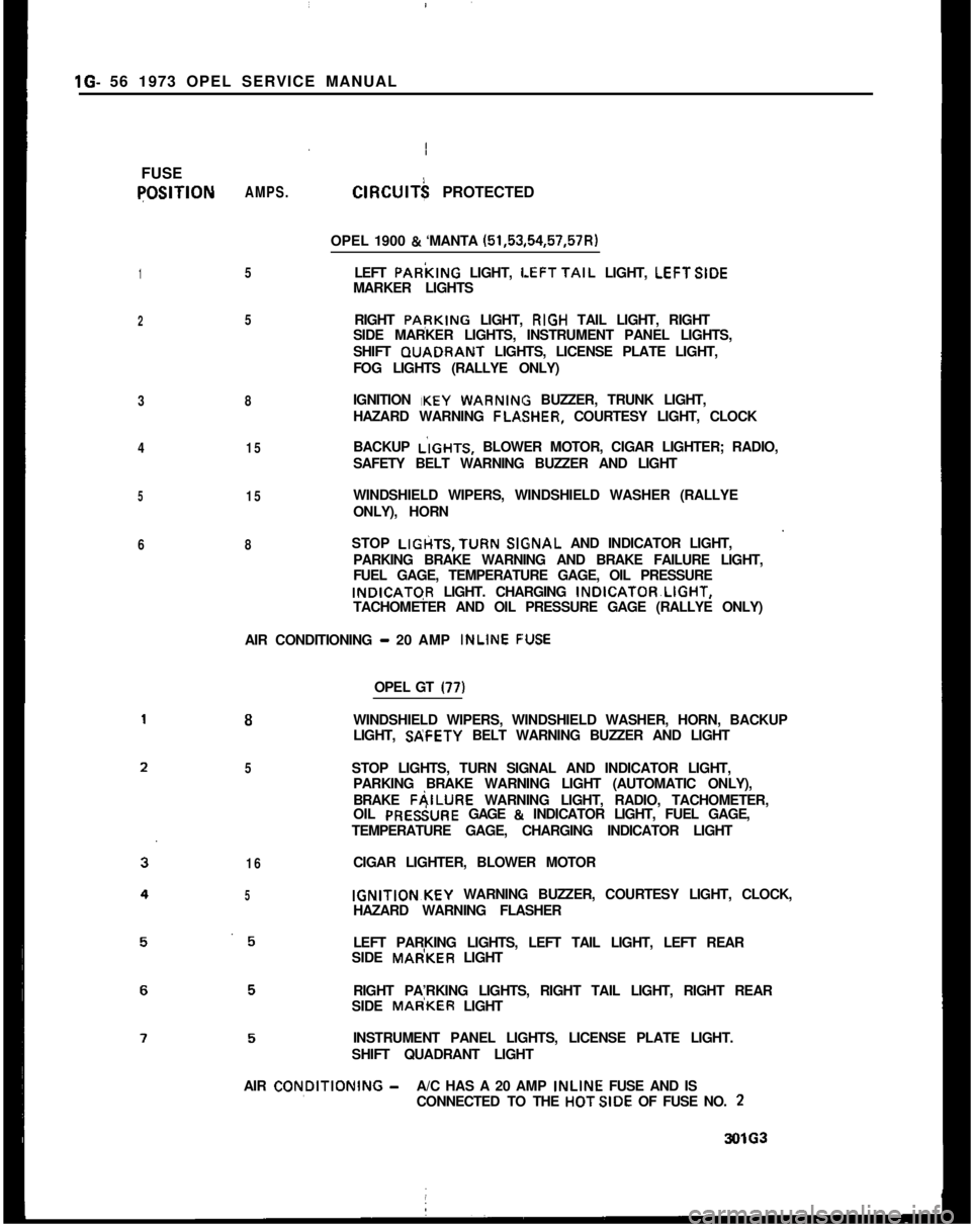
FUSEqOSlTlON
1
2
3
4
5
6AMPS.
5
5
8
15
15
8ClRClJlT$ PROTECTED
OPEL 1900
& ‘MANTA (51,53,54,57,57R)
LEFT PARkING LIGHT,
LEFTTAIL LIGHT, LEFTSIDE
MARKER LIGHTS
RIGHT PApKING LIGHT, RIGH TAIL LIGHT, RIGHT
SIDE MARKER LIGHTS, INSTRUMENT PANEL LIGHTS,
SHIFT GUADRANT LIGHTS, LICENSE PLATE LIGHT,
FOG LIGHTS (RALLYE ONLY)
IGNITION IKEY
WARNIN BUZZER, TRUNK LIGHT,
HAZARD WARNING FLA,SHER, COURTESY LIGHT, CLOCK
BACKUP L’IGHTS, BLOWER MOTOR, CIGAR LIGHTER; RADIO,
SAFETY BELT WARNING BUZZER AND LIGHT
WINDSHIELD WIPERS, WINDSHIELD WASHER (RALLYE
ONLY), HORN
STOP LIGtiTS,TURN
SlGsNAL AND INDICATOR LIGHT,
PARKING BRAKE WARNING AND BRAKE FAILURE LIGHT,
FUEL GAGE, TEMPERATURE GAGE, OIL PRESSUREINDICATGR LIGHT. CHARGING INDICATOR~LIGHT,
TACHOMETER AND OIL PRESSURE GAGE (RALLYE ONLY)
AIR CONDITIONING
- 20 AMP INLINE F:USE
8
5
16
5OPEL GT
(77)WINDSHIELD WIPERS, WINDSHIELD WASHER, HORN, BACKUP
LIGHT, SP;FETY BELT WARNING BUZZER AND LIGHT
STOP LIGHTS, TURN SIGNAL AND INDICATOR LIGHT,
PARKING BRAKE WARNING LIGHT (AUTOMATIC ONLY),
BRAKE FAILURE WARNING LIGHT, RADIO, TACHOMETER,
OIL PRESiURE GAGE
& INDICATOR LIGHT, FUEL GAGE,
TEMPERATURE GAGE, CHARGING INDICATOR LIGHT
CIGAR LIGHTER, BLOWER MOTORIGNITION~KEY WARNING BUZZER, COURTESY LIGHT, CLOCK,
HAZARD WARNING FLASHER
LEFT PARKING LIGHTS, LEFT TAIL LIGHT, LEFT REAR
SIDE MAdKER LIGHT
RIGHT PA’RKING LIGHTS, RIGHT TAIL LIGHT, RIGHT REAR
SIDE MAdKER LIGHT
INSTRUMENT PANEL LIGHTS, LICENSE PLATE LIGHT.
SHIFT QUADRANT LIGHT
AIR CON,DlTlONlNG
-A/C HAS A 20 AMP INLINE FUSE AND IS
CONNECTED TO THE HOTSIDE OF FUSE NO. 23OlG3
Page 79 of 625
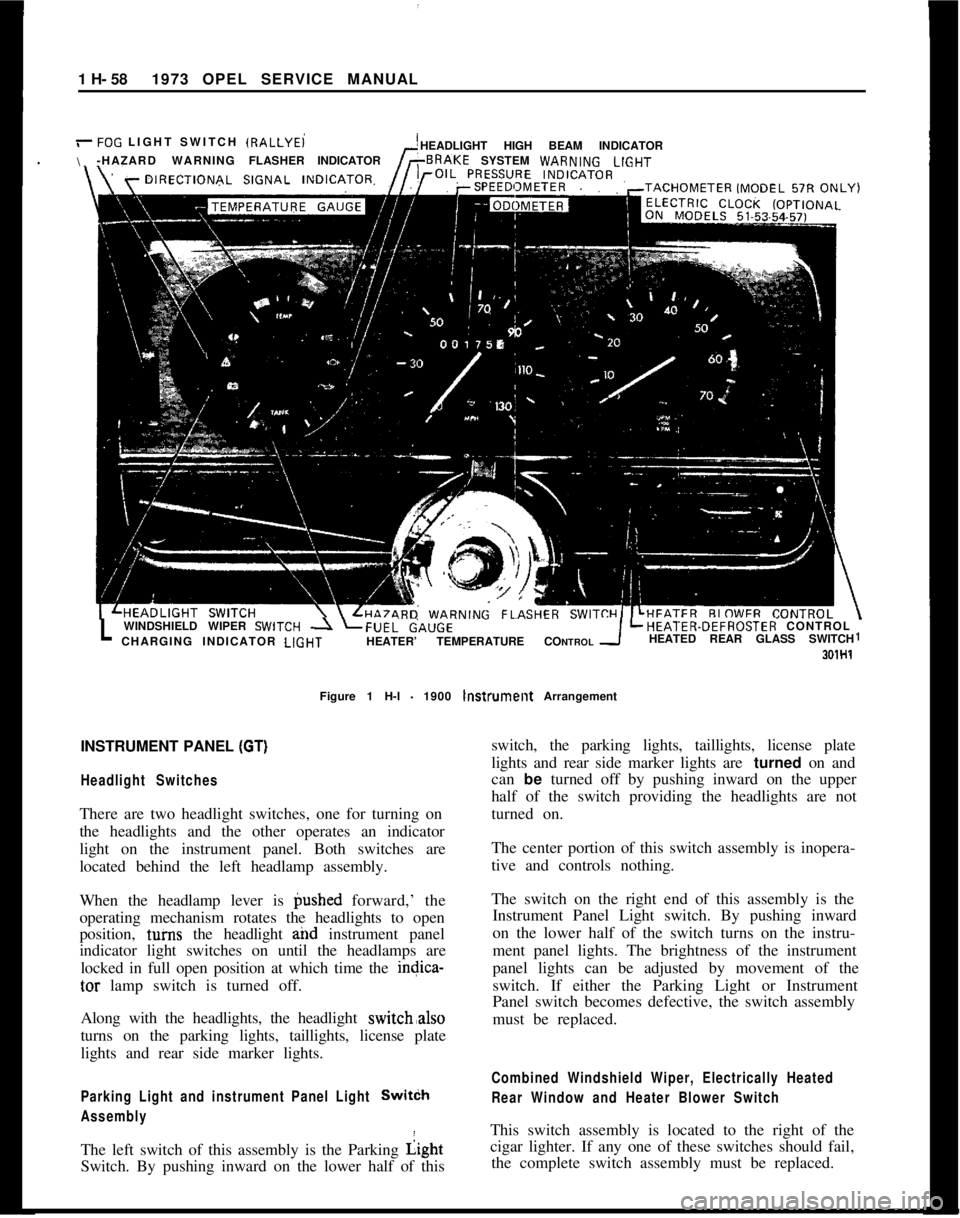
1 H- 581973 OPEL SERVICE MANUAL
/-FOG LIGHT SWITCH IRALLYEi
\HEADLIGHT HIGH BEAM INDICATOR
-HAZARD WARNINGFLASHERINDICATORSYSTEM WARN,NGLlGHT
LWINDSHIELD WIPER SWlTCH -1 LFUEL&,UGELHEATER-DEFROSTER CONTROL
CHARGING INDICATOR LlGHTHEATER’ TEMPERATURE CONTROLHEATED REAR GLASS SWITCH1
301H1Figure 1 H-l
- 1900 lnstrumellt Arrangement
INSTRUMENT PANEL
(GT)I
Headlight SwitchesThere are two headlight switches, one for turning on
the headlights and the other operates an indicator
light on the instrument panel. Both switches are
located behind the left headlamp assembly.
When the headlamp lever is @shed forward,’ the
operating mechanism rotates the headlights to open
position, tuins the headlight and instrument panel
indicator light switches on until the headlamps are
locked in full open position at which time the indica-
tar lamp switch is turned off.
Along with the headlights, the headlight switch,also
turns on the parking lights, taillights, license plate
lights and rear side marker lights.
Parking Light and instrument Panel Light SwitCh
AssemblyThe left switch of this assembly is the Parking Light
Switch. By pushing inward on the lower half of thisswitch, the parking lights, taillights, license plate
lights and rear side marker lights are turned on and
can be turned off by pushing inward on the upper
half of the switch providing the headlights are not
turned on.
The center portion of this switch assembly is inopera-
tive and controls nothing.
The switch on the right end of this assembly is the
Instrument Panel Light switch. By pushing inward
on the lower half of the switch turns on the instru-
ment panel lights. The brightness of the instrument
panel lights can be adjusted by movement of the
switch. If either the Parking Light or Instrument
Panel switch becomes defective, the switch assembly
must be replaced.
Combined Windshield Wiper, Electrically Heated
Rear Window and Heater Blower SwitchThis switch assembly is located to the right of the
cigar lighter. If any one of these switches should fail,
the complete switch assembly must be replaced.
Page 80 of 625

/
I
IINSTRUMENT PANELlH- 59
Figure 1 H-2
- GT Instrument and Switch Arrangement
The Wihdshield Wipers have two-speed operation.
By pushing the lower half of the switch inward to the
first stop, the wipers will operate at half speed and
by deprbssing to the second stop will provide full
speed oieration. When the switch is returned to the
off posit/on, the wiper blades automatically return to
their park position.
I
The El
this optlpn. The engine must be running before
suffi-cient current can be generated to energize this circuit
even th6ugh the switch is depressed to the “ON”
position! When the window is being heated, a warm-
ing light’on the instrument panel will glow. This light
is locate? below the left ventilation inlet.
The
Heiter Blower Switch is a three position switch.
By depressing the lower half of the switch to the first
stop,
th& blower will operate at low speed. Whendepressdd to the second stop, the blower will operate
at high ipeed.
Four Way Hezrerd Warning Flasher SwitchThe
hazard warning flasher switch is located below
the heater controls in the center console. By
depress-ing the lower half of the switch, all four turn- signal
lamps flash at the same time. Although this system
makes use of the regulat turn signal system, it has a
separate feed wire to the switch which allows for its
operation even with the ignition switch and doors
locked. No vehicle should be driven with this system
in operation because of its universal meaning “This
Vehicle Is Not Moving”. To turn the system off,
simply depress the upper half of the switch.
MAJOR REPAIR
Removal of Instrument Cluster Housing Assembly.Opel 1900 Manta
Before starting any instrument panel repair, always
disconnect battery ground cable first.
I
Page 93 of 625
1 J- 72 1973 OPEL SERVICE MANUAL
I
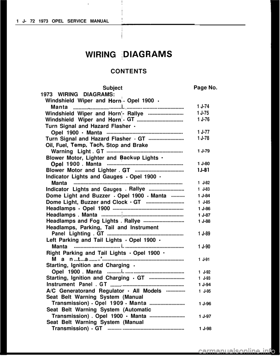
WIRING IDIAGRAMS
CONTENTS
Subject
1973 WIRING DIAGRAMS: Windshield Wiper and
Horn:- Opel 1900 -
Manta....................................I.............. ..............................
Windshield Wiper and Horn’- Rallye ..........................
Windshield Wiper
andHorn!-GT
..................................
Turn Signal and Hazard Flasher
-
Opel 1900 - Manta !
........................................................
Turn Signal and Hazard Flasher
- GT ..........................
Oil, Fuel,
Temp.: Tach, Stop and Brake
Warning Light
.GT........................................................
Blower Motor, Lighter and
Rackup Lights -
Qpel 1900.Manta ........................................................
Blower Motor and Lighter
.,GT....................................
Indicator Lights and Gauges
- Opel 1900 -
Manta ........................................................................\
........
Indicator Lights
andGauges.Rallye ..........................
Dome Light and Buzzer
- Opel 1900 - Manta..........
Dome Light, Buzzer and Clock - GT ............................
Headlamps
- Opel 1900 ’
....................................................
Headlamps
.Mantaj............................................................
Headlamps and Fog Lights
.Rallye ..............................
Headlamps, Parking, Tail and Instrument
PanelLighting.GT ........................................................
Left Parking and Tail Lights
- Opel 1900 -
Manta ..................................i.............................................
Right Parking and Tail Lights
- Opel 1900 -
Manta................. ..*............................................................
Starting, Ignition and Charging
-
Opel 1900.Manta..........i.............................................
Starting, Ignition and Charging
- GT ..........................
Instrument
Panel.GT ......................................................
A/C Generatorand Regulator
- All Models..............
Seat Belt Warning System (Manual Transmission)
-Opel1909-Manta ..........................
Seat Belt Warning System (Automatic Transmission)
.Opel 1900 - Manta..........................
Seat Belt Warning System (Manual Transmission)
- GT........................................................ Page No.
1 J-74
1 J-75
1 J-76
1 J-77
1 J-78
1 J-79
1 J-80
lJ-81
1 J-82
1 J-83
1 J-84
1 J-85
1 J-86
1 J-87
1 J-88
1 J-89
1 J-90
1 J-91
1 J-92
1 J-93
1 J-94
1 J-95
1 J-96
1 J-97
1 J-98
Page 100 of 625

I
WIRING DIAGRAMS15.79
IIFigure lJ-6
Oil. Fuel. Temp. Tach, Stop and Brake Warning Light. GT
I
Page 273 of 625

5B- 141973 OPEL SERVICE MANUALConditionPossible CauseCorrection2. Partial system failure.2. Check front and rear brake system
and repair, if necessary. Also, check
brake warning light, if a failed
system is found and light did not
function.
3. Excessively worn shoe
and lining.3. Check and replace in axle sets.
4. Piston in caliper stuck
or sluggish.4. Remove caliper and rebuild.
5. Fading brakes due to
incorrect lining.
6. Vacuum leak.5. Remove and replace with original
equipment lining.
6. Check for ruptured hose or loose
attachment.
Excessive Pedal Travel1. Partial brake system
failure.1. Check both front and rear system
for a failure and repair. Also, check
warning light
- it should have indi-
cated a failure.
2. Insufficient fluid in
master cylinder.
3. Poor rear brake
adjustment.2. Fill reservoirs with approved
brake fluid. Check for leaks.
3. Adjust rear brake per
specifications.
4. Air trapped in system.4. Bleed system.
5. Bent shoe and lining.5. Replace axle set of shoe and
lining.
Dragging Brakes (A very
light drag is present in
all disc brakes
immediately after pedal
is released.)1. Master cylinder pistons
not returning correctly.1. With reservoir cover off, check
for fluid spurt at bypass holes as
pedal is depressed. Adjust push rod,
if necessary, or rebuild master
cylinder.
2. Restricted brake tubes2. Check for soft hoses or damaged
or hoses.tubes and replace with new hoses and
new double-walled steel brake tubing.
3. Incorrect parking brake
adjustment on rear brakes.3. Check and readjust to correct
specifications.
Grabbing or Uneven Braking
Action (All conditions
listed under “Pulls”
.)4. Check valve installed in
outlet to front disc brakes.
1. Malfunction of power
brake unit.4. Check master cylinder outlet and
remove check valve if present.
1. Check operation and repair, if
necessary.