oil pump OPEL MANTA 1973 Owner's Guide
[x] Cancel search | Manufacturer: OPEL, Model Year: 1973, Model line: MANTA, Model: OPEL MANTA 1973Pages: 625, PDF Size: 17.22 MB
Page 410 of 625
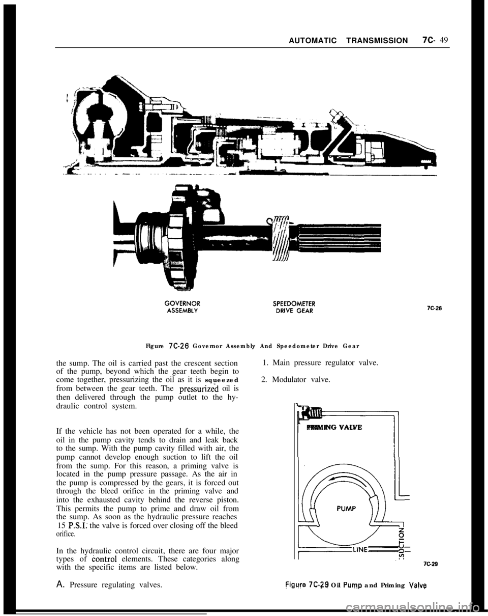
AUTOMATIC TRANSMISSION7c- 49Figure 7C-26 Governor Assembly And Speedometer Drive Gearthe sump. The oil is carried past the crescent section
of the pump, beyond which the gear teeth begin to
come together, pressurizing the oil as it is squeezed
from between the gear teeth. The pressurizeh oil is
then delivered through the pump outlet to the hy-
draulic control system.1. Main pressure regulator valve.
2. Modulator valve.
mPRIMING VALVE
If the vehicle has not been operated for a while, the
oil in the pump cavity tends to drain and leak back
to the sump. With the pump cavity filled with air, the
pump cannot develop enough suction to lift the oil
from the sump. For this reason, a priming valve is
located in the pump pressure passage. As the air in
the pump is compressed by the gears, it is forced out
through the bleed orifice in the priming valve and
into the exhausted cavity behind the reverse piston.
This permits the pump to prime and draw oil from
the sump. As soon as the hydraulic pressure reaches
15
PSI: the valve is forced over closing off the bleed
orifice.PRIMING VALVE
In the hydraulic control circuit, there are four major
types of iontrol elements. These categories along
with the specific items are listed below.
A. Pressure regulating valves.
Fieure 7C-7.9 Oil Puvp and Priming Valve
Page 411 of 625
712.501973 OPEL SERVICE MANUAL
3. Detent pressure regulator valve.
4. 1 - 2 Accumulator valve.
5. Governor.
B. Selector valves (manually and hydraulically con-
trolled).
I. Manual valve.
2. Detent valve.
3. 1
- 2 Shift valve.
4. 2
- 3 Shift valve.
5. 3
- 2 Downshift control valve.
6. Manual low and reverse control valve.
7. Boost control valve.
C. Timing Valves.
1. Low speed downshift timing valve.
2. High speed downshift timing valve.
3. Second clutch orifice valve.
D. Accumulators.
1. 1
- 2 Accumulator.
2. Low servo piston.
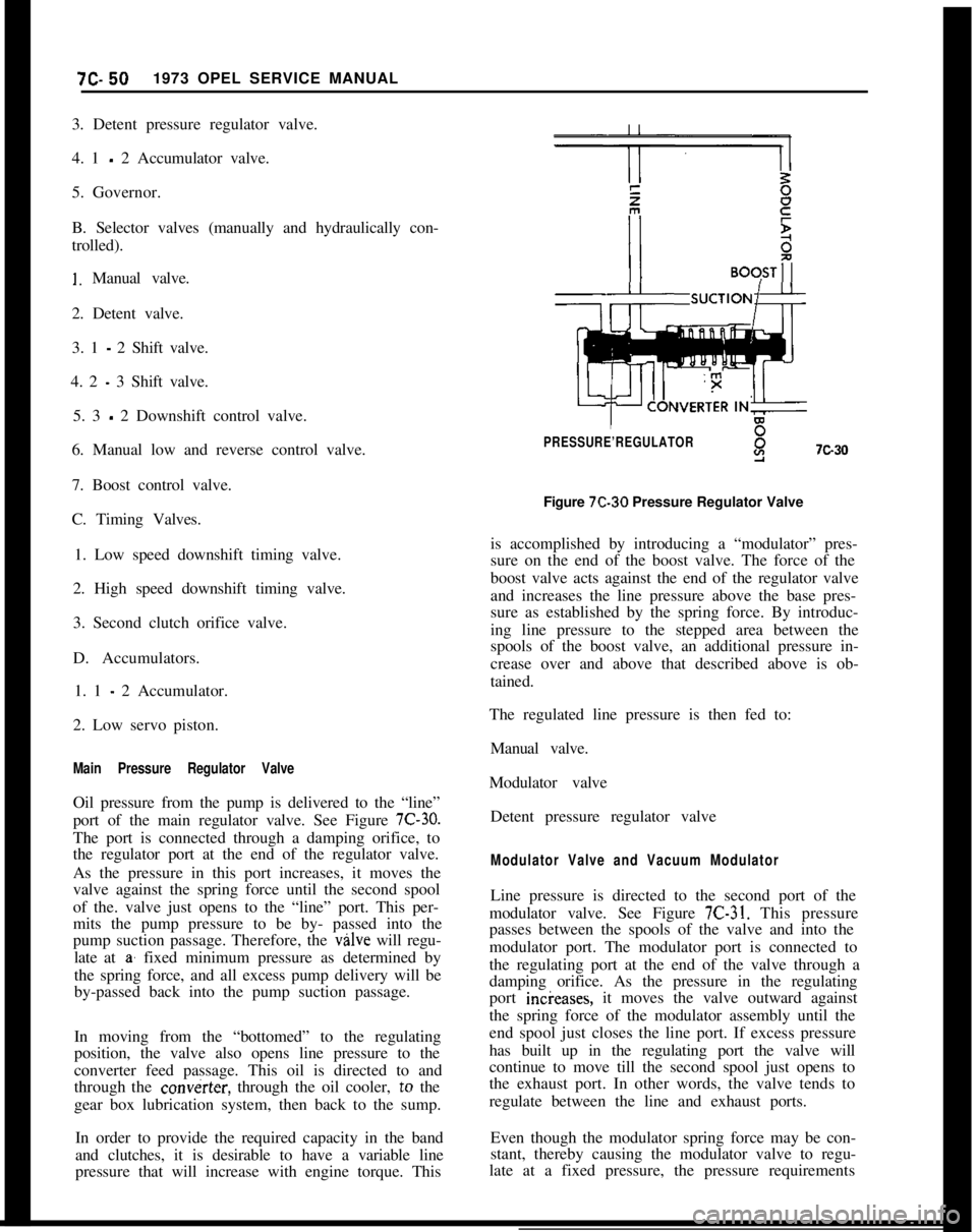
Main Pressure Regulator ValveOil pressure from the pump is delivered to the “line”
port of the main regulator valve. See Figure
7C-30.The port is connected through a damping orifice, to
the regulator port at the end of the regulator valve.
As the pressure in this port increases, it moves the
valve against the spring force until the second spool
of the. valve just opens to the “line” port. This per-
mits the pump pressure to be by- passed into the
pump suction passage. Therefore, the valve will regu-
late at
a’ fixed minimum pressure as determined by
the spring force, and all excess pump delivery will be
by-passed back into the pump suction passage.
In moving from the “bottomed” to the regulating
position, the valve also opens line pressure to the
converter feed passage. This oil is directed to and
through the
cow&x, through the oil cooler, to the
gear box lubrication system, then back to the sump.
In order to provide the required capacity in the band
and clutches, it is desirable to have a variable line
pressure that will increase with engine torque. This
PRESSURE’REGULATORY7c30Figure 7C-30 Pressure Regulator Valve
is accomplished by introducing a “modulator” pres-
sure on the end of the boost valve. The force of the
boost valve acts against the end of the regulator valve
and increases the line pressure above the base pres-
sure as established by the spring force. By introduc-
ing line pressure to the stepped area between the
spools of the boost valve, an additional pressure in-
crease over and above that described above is ob-
tained.
The regulated line pressure is then fed to:
Manual valve.
Modulator valve
Detent pressure regulator valve
Modulator Valve and Vacuum ModulatorLine pressure is directed to the second port of the
modulator valve. See Figure
7C-31. This pressure
passes between the spools of the valve and into the
modulator port. The modulator port is connected to
the regulating port at the end of the valve through a
damping orifice. As the pressure in the regulating
port incieases, it moves the valve outward against
the spring force of the modulator assembly until the
end spool just closes the line port. If excess pressure
has built up in the regulating port the valve will
continue to move till the second spool just opens to
the exhaust port. In other words, the valve tends to
regulate between the line and exhaust ports.
Even though the modulator spring force may be con-
stant, thereby causing the modulator valve to regu-
late at a fixed pressure, the pressure requirements
Page 426 of 625
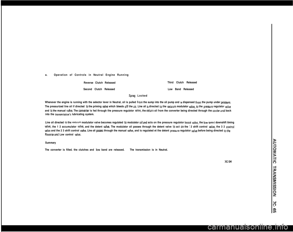
a.Operation of Controls in Neutral Engine Running
Reverse Clutch ReleasedThird Clutch Released
Second Clutch ReleasedSprag LockedLow Band Released
Whenever the engine is running with the selector lever in Neutral, oil is pulled from the sump into the oil pump and is dispensed from the pump under preure.
The pressurized line oil if directed
to the priming valve which bleeds off the air. Line oil is directed to the vacuum modulator YBIYB, to the prexwre regulator valveand
to the manual veIve. The converter is fed through the pressure regulator MIYB. the return oil from the converter being directed through the coalerand back
into the transmisGon’s lubricating system.
Line oil directed
to the vacuum modulator valve becomes regulated to modulator oiland acts on the pressure regulator boosI YBCB. the IDW speed downshift timing
valve. the 1 2 accumulator MIYB. and the detent valve. The modulator oil passes through the detent valve to act 00 the I 2 shift control give. the 3 2 control
valve and the 2 3 shift control valve. Line oil pasres through the manual v&e. and is regulated et the detent preaure regulator valve before being directed to the
Reverseand Low control delve.Summary
The converter is filled. the clutches and
IDW band are released.The transmission is in Neutral.
Page 443 of 625
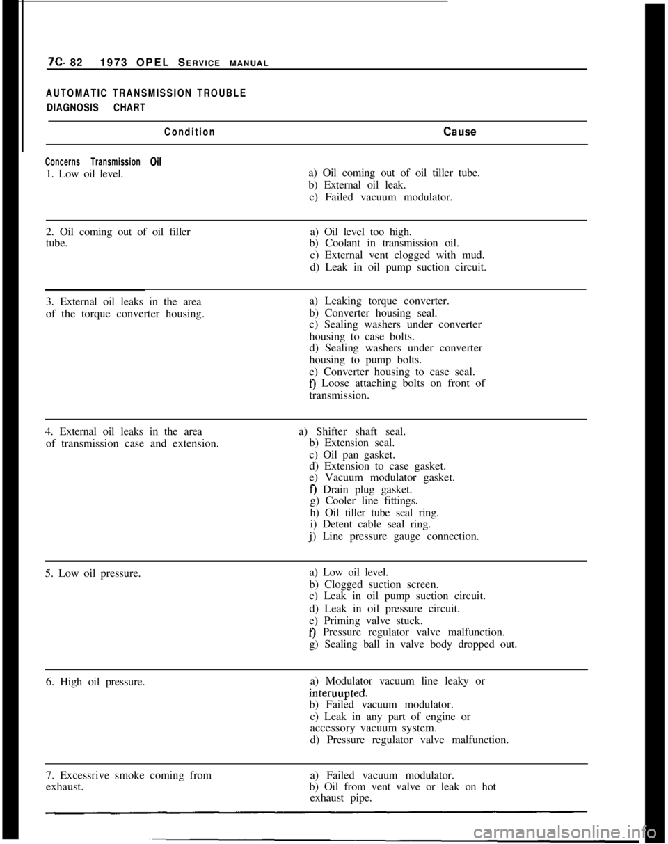
7C- 821973 OPEL SERVICE MANUALAUTOMATIC TRANSMISSION TROUBLE
DIAGNOSIS CHART
Condition
CEllE.e
Concerns Transmission Oil1. Low oil level.a) Oil coming out of oil tiller tube.
b) External oil leak.
c) Failed vacuum modulator.
2. Oil coming out of oil filler
tube.a) Oil level too high.
b) Coolant in transmission oil.
c) External vent clogged with mud.
d) Leak in oil pump suction circuit.
3. External oil leaks in the area
of the torque converter housing.a) Leaking torque converter.
b) Converter housing seal.
c) Sealing washers under converter
housing to case bolts.
d) Sealing washers under converter
housing to pump bolts.
e) Converter housing to case seal.
fj Loose attaching bolts on front of
transmission.
4. External oil leaks in the area
of transmission case and extension.a) Shifter shaft seal.
b) Extension seal.
c) Oil pan gasket.
d) Extension to case gasket.
e) Vacuum modulator gasket.
f) Drain plug gasket.
g) Cooler line fittings.
h) Oil tiller tube seal ring.
i) Detent cable seal ring.
j) Line pressure gauge connection.
5. Low oil pressure.a) Low oil level.
b) Clogged suction screen.
c) Leak in oil pump suction circuit.
d) Leak in oil pressure circuit.
e) Priming valve stuck.
t) Pressure regulator valve malfunction.
g) Sealing ball in valve body dropped out.
6. High oil pressure.a) Modulator vacuum line leaky orinteruupted.
b) Failed vacuum modulator.
c) Leak in any part of engine or
accessory vacuum system.
d) Pressure regulator valve malfunction.
7. Excessrive smoke coming from
exhaust.a) Failed vacuum modulator.
b) Oil from vent valve or leak on hot
exhaust pipe.
Page 444 of 625

AUTOMATIC TRANSMISSION 7C- 83
ConditionCause
Starting
1. No starting in any driverange.a) Low oil level.
b) Clogged suction screen.
c) Manual valve linkage or inner trans-
mission selector lever disconnected.
d) Input shaft broken.e) Pressure regulator valve stuck in open
position. -0 Failed oil pump.
2. No starting in any drive range
for a time. Driving possible only
after repeatedly moving selector
lever to and fro.Manual valve position does not coincide
with valve body channels:
a) Selector lever shaft retaining
pin dropped out.
b) Connecting rod to manual valve
shifting.
c) Selector lever shaft nut loose.
3. No starting after shifting
lever from “P” to “D”, “S”, or “L”
(inadequate engine acceleration).a) Parking
paw1 does not disengage.
4. Sudden starting only after
increase of engine RPM.a) Band servo piston jamming.
b) Low oil level.
c) Oil pump defective.
d) Oil screen missing.
e) Sealing ball in valve body dropped out
5. Heavy jerking when starting.a) Low oil pressure.
b) Wrong modulator valve.
c) Pressure regulator valve stuck.
d) Sealing ball in valve body dropped out.
6. No starting in “D” or “S”
range, but in “L” and “R” range.a) Input sprag installed backwards.
b) Input sprag failure.
7. No starting in “D” or “S” and
“L” (proper driving in “R”; see
also point 9).a) Band worn, does not grip.
b) Band servo piston jamming.
c) Excessive leak in band servo.
d) Parking
paw1 does not disengage.
Page 445 of 625
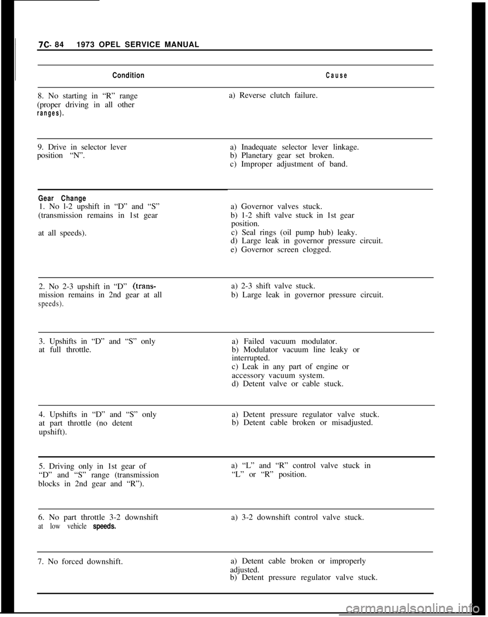
7C. 841973 OPEL SERVICE MANUALConditionCause8. No starting in “R” range
(proper driving in all other
ranges).a) Reverse clutch failure.
9. Drive in selector lever
position “N”.a) Inadequate selector lever linkage.
b) Planetary gear set broken.
c) Improper adjustment of band.
Gear Change1. No l-2 upshift in “D” and “S”
(transmission remains in 1st gear
at all speeds).a) Governor valves stuck.
b) 1-2 shift valve stuck in 1st gear
position.
c) Seal rings (oil pump hub) leaky.
d) Large leak in governor pressure circuit.
e) Governor screen clogged.
2. No 2-3 upshift in “D” (trans-
mission remains in 2nd gear at all
speeds).a) 2-3 shift valve stuck.
b) Large leak in governor pressure circuit.
3. Upshifts in “D” and “S” only
at full throttle.a) Failed vacuum modulator.
b) Modulator vacuum line leaky or
interrupted.
c) Leak in any part of engine or
accessory vacuum system.
d) Detent valve or cable stuck.
4. Upshifts in “D” and “S” only
at part throttle (no detent
upshift).a) Detent pressure regulator valve stuck.
b) Detent cable broken or misadjusted.
5. Driving only in 1st gear of
“D” and “S” range (transmission
blocks in 2nd gear and “R”).a) “L” and “R” control valve stuck in
“L” or “R” position.
6. No part throttle 3-2 downshift
at low vehicle speeds.a) 3-2 downshift control valve stuck.
7. No forced downshift.a) Detent cable broken or improperly
adjusted.
b) Detent pressure regulator valve stuck.
Page 446 of 625
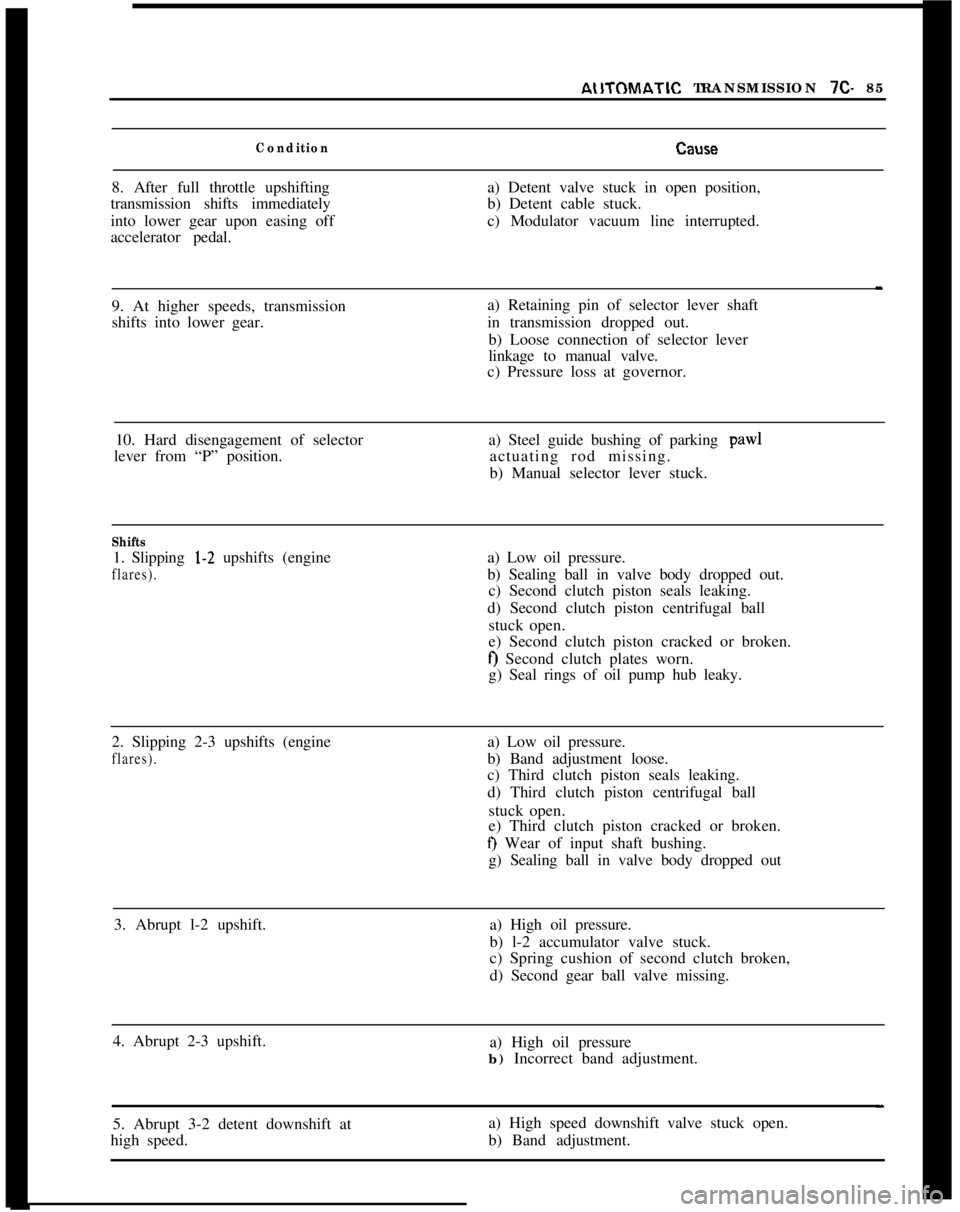
AlITOMATIC TRANSMISSION 7C- 85
ConditionCtSlSl?8. After full throttle upshifting
transmission shifts immediately
into lower gear upon easing off
accelerator pedal.a) Detent valve stuck in open position,
b) Detent cable stuck.
c) Modulator vacuum line interrupted.
9. At higher speeds, transmission
shifts into lower gear.a) Retaining pin of selector lever shaft
in transmission dropped out.
b) Loose connection of selector lever
linkage to manual valve.
c) Pressure loss at governor.
10. Hard disengagement of selector
lever from “P” position.a) Steel guide bushing of parking
paw1actuating rod missing.
b) Manual selector lever stuck.
Shifts1. Slipping l-2 upshifts (engine
flares).a) Low oil pressure.
b) Sealing ball in valve body dropped out.
c) Second clutch piston seals leaking.
d) Second clutch piston centrifugal ball
stuck open.
e) Second clutch piston cracked or broken.
f) Second clutch plates worn.
g) Seal rings of oil pump hub leaky.
2. Slipping 2-3 upshifts (engine
flares).a) Low oil pressure.
b) Band adjustment loose.
c) Third clutch piston seals leaking.
d) Third clutch piston centrifugal ball
stuck open.
e) Third clutch piston cracked or broken.
f) Wear of input shaft bushing.
g) Sealing ball in valve body dropped out
3. Abrupt l-2 upshift.a) High oil pressure.
b) l-2 accumulator valve stuck.
c) Spring cushion of second clutch broken,
d) Second gear ball valve missing.
4. Abrupt 2-3 upshift.
a) High oil pressure
b) Incorrect band adjustment.
5. Abrupt 3-2 detent downshift at
high speed.a) High speed downshift valve stuck open.
b) Band adjustment.
Page 447 of 625
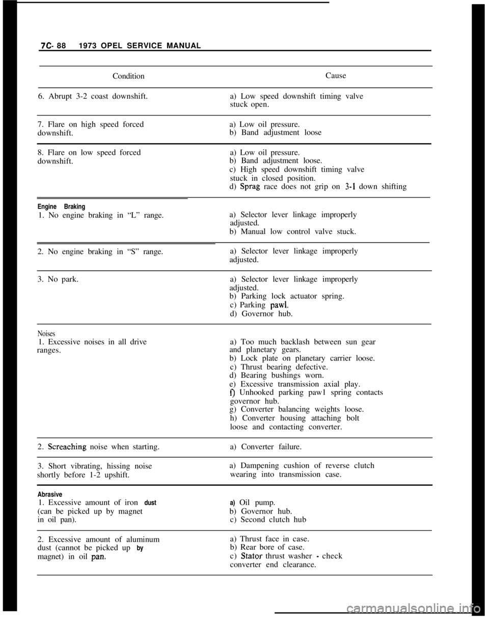
7C- 881973 OPEL SERVICE MANUAL
Condition
6. Abrupt 3-2 coast downshift.Cause
a) Low speed downshift timing valve
stuck open.
7. Flare on high speed forceda) Low oil pressure.
downshift.b) Band adjustment loose
8. Flare on low speed forced
downshift.a) Low oil pressure.
b) Band adjustment loose.
c) High speed downshift timing valve
stuck in closed position.
d) Sprag race does not grip on 3-1 down shifting
Engine Braking
1. No engine braking in “L” range.a) Selector lever linkage improperly
adjusted.
b) Manual low control valve stuck.
2. No engine braking in “S” range.a) Selector lever linkage improperly
adjusted.
3. No park.a) Selector lever linkage improperly
adjusted.
b) Parking lock actuator spring.
c) Parking pawl.
d) Governor hub.
Noises1. Excessive noises in all drive
ranges.a) Too much backlash between sun gear
and planetary gears.
b) Lock plate on planetary carrier loose.
c) Thrust bearing defective.
d) Bearing bushings worn.
e) Excessive transmission axial play.
f) Unhooked parking paw1 spring contacts
governor hub.
g) Converter balancing weights loose.
h) Converter housing attaching bolt
loose and contacting converter.
2. Screaching noise when starting.
3. Short vibrating, hissing noise
shortly before 1-2 upshift.a) Converter failure.
a) Dampening cushion of reverse clutch
wearing into transmission case.
Abrasive
1. Excessive amount of iron dust
(can be picked up by magnet
in oil pan).a) Oil pump.
b) Governor hub.
c) Second clutch hub
2. Excessive amount of aluminum
dust (cannot be picked up by
magnet) in oil pan.a) Thrust face in case.
b) Rear bore of case.
c) Stator thrust washer
- check
converter end clearance.
Page 449 of 625

7C- 881973 OPEL SERVICE MANUALCONVERTER
OUT\
/
2ND CLUTCHa!EI1
CONVERTER iOUT
x
PRIMING VALVE
BORE
\
REVERSE
CLUTCH
:. -q
MODULATOR -
EXHAUST
REVERSE CLUTCH
INTERMEDIATE
2ND CLUTCH
3RD CLUTCHBOOST
7674Figure 7C-74 Oil Pump Passages
Page 464 of 625
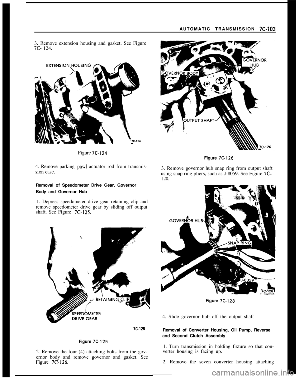
AUTOMATIC TRANSMISSION 712-1033. Remove extension housing and gasket. See Figure7C- 124.
Figure 7C-124
4. Remove parking
paw1 actuator rod from transmis-
sion case.
Removal of Speedometer Drive Gear, Governor
Body and Governor Hub
1. Depress speedometer drive gear retaining clip and
remove speedometer drive gear by sliding off output
shaft. See Figure
7C-125.
7c-125Figure 7C-125
2. Remove the four (4) attaching bolts from the gov-
ernor body and remove governor and gasket. See
Figure
7C-126.Figure 7C-126
3. Remove governor hub snap ring from output shaft
using snap ring pliers, such as J-8059. See Figure 7C-
128.Figure 7C-128
4. Slide governor hub off the output shaft
Removal of Converter Housing, Oil Pump, Reverse
and Second Clutch Assembly
1. Turn transmission in holding fixture so that con-
verter housing is facing up.
2. Remove the seven converter housing attaching