ad blue OPEL MANTA 1973 Service Manual
[x] Cancel search | Manufacturer: OPEL, Model Year: 1973, Model line: MANTA, Model: OPEL MANTA 1973Pages: 625, PDF Size: 17.22 MB
Page 12 of 625
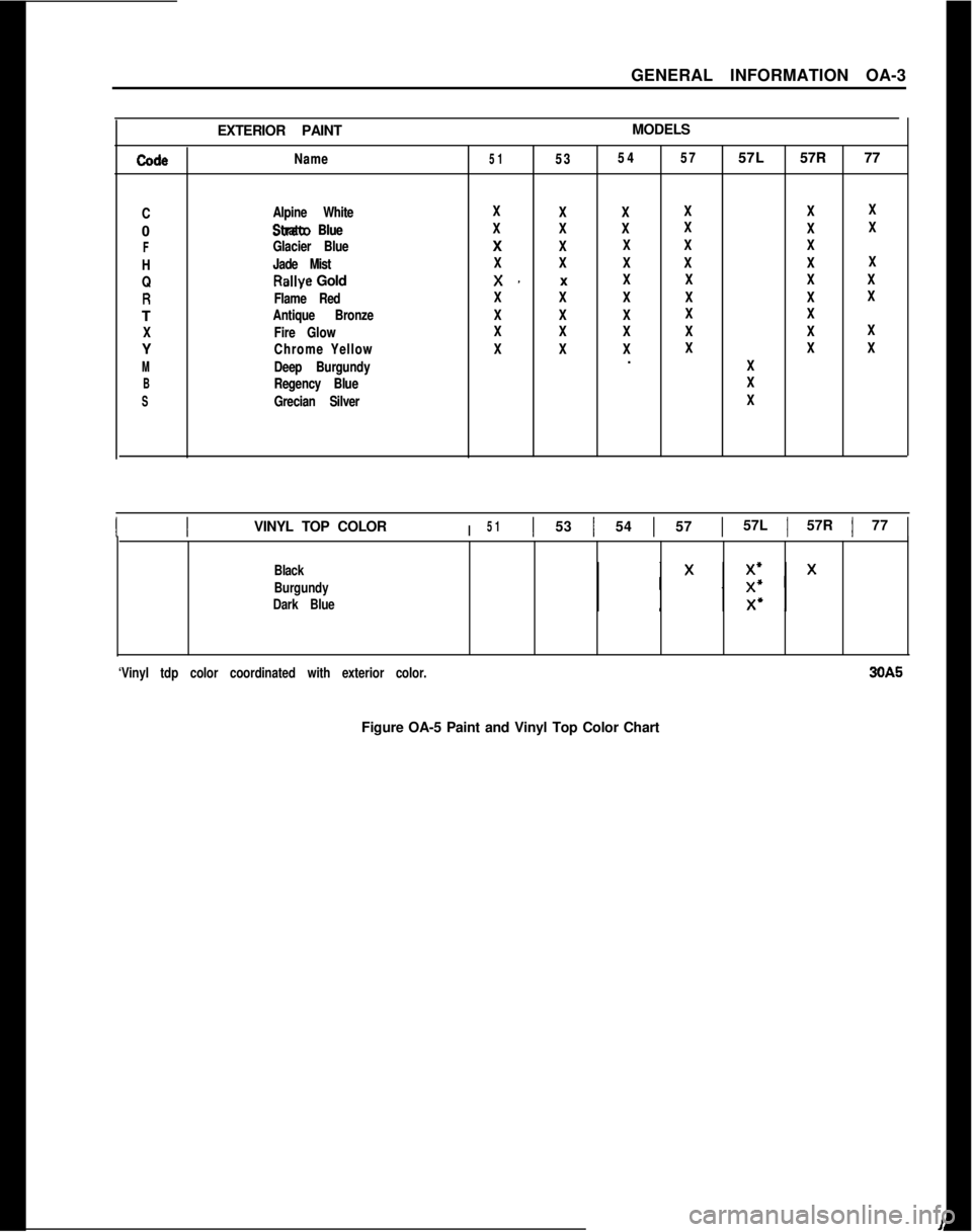
GENERAL INFORMATION OA-3
EXTERIOR PAINTMODELScodacodaName Name51 5153 5354 5457 5757L 57L57R 77 57R 77
C CAlpine White Alpine White0 0
strata Blue Strato Blue
F FGlacier Blue Glacier Blue
H HJade Mist Jade Mist
Q Q
Rallye GoldRallye Gold
RRFlame Red Flame RedT T
Antique Bronze Antique Bronze
X XFire Glow Fire GlowY Y
Chrome Yellow Chrome Yellow
M MDeep Burgundy Deep Burgundy
B BRegency Blue Regency Blue
S SGrecian Silver Grecian SilverX X
X XX XX XX XX X
X XX XX XX X
X XX XX X
X XX XX XX X
X XX XX XX XX XX X
x. xx. xX XX XX XX X
X XX XX XX XX XX X
X XX XX XX XX X
X XX XX XX XX XX X
X XX XX XX XX XX X. .
X X
X X
X X
I IVINYL TOP COLORI511 53 1 54 1 571 57L 1 57R 1 77 1
Black
Burgundy
Dark Blue
‘Vinyl tdp color coordinated with exterior color.30A5
Figure OA-5 Paint and Vinyl Top Color Chart
Page 29 of 625
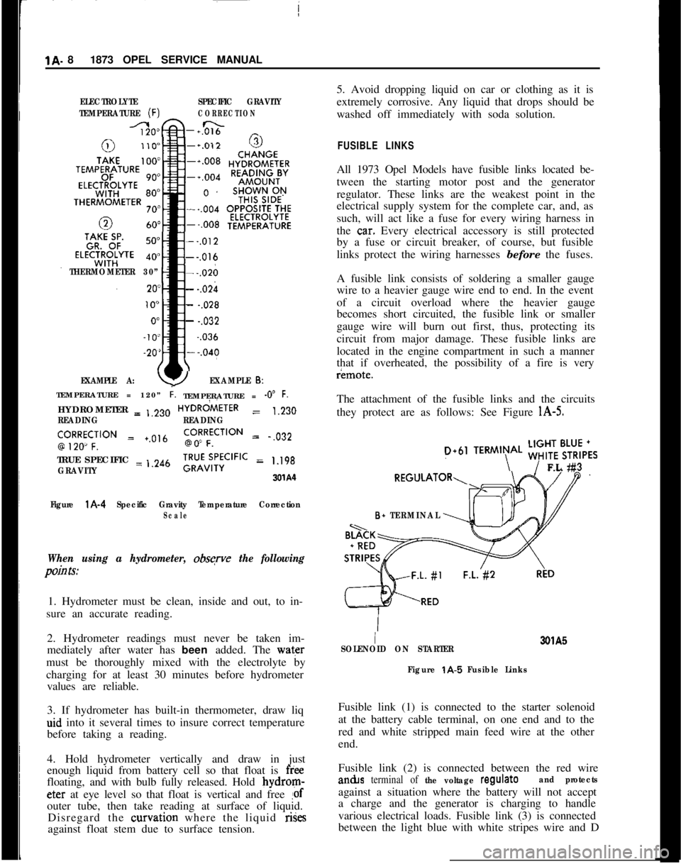
1A. 81873 OPEL SERVICE MANUALELECTROLYTESPECIFIC GRAVITY
TEMPERATURE
(F)CORRECTION
-+0&&n _
THERMOMETER 30”
EXAMPLE A:
--,012---,016---,026
- -.02h
- -.028
- -.032~
-.036
YEXAMPLE 6:TEMPERATURE = 120”
i.TEMPERATURE = -0” F.HYDROMETER = ,,230HYDRdiETER
= 1.230
READINGREADING
‘,9R2Ro~CF;‘“” = +.0,6go!RFfCilON = .,032
TRUE SPECIFIC = ,.246
GRAVITY;RU”v;,‘;CIFIC = 1.198
3xA‘l
Figure
l A-4 Specific Gravity Temperature CorrectionScale
When using a hydrometer, obsqve the following
pain Is:1. Hydrometer must be clean, inside and out, to in-
sure an accurate reading.
2. Hydrometer readings must never be taken im-
mediately after water has been added. The water
must be thoroughly mixed with the electrolyte by
charging for at least 30 minutes before hydrometer
values are reliable.
3. If hydrometer has built-in thermometer, draw liq
aid into it several times to insure correct temperature
before taking a reading.
4. Hold hydrometer vertically and draw in just
enough liquid from battery cell so that float is
freefloating, and with bulb fully released. Hold bydrom-eter at eye level so that float is vertical and free
!ofouter tube, then take reading at surface of liquid.
Disregard the curvation where the liquid rises
against float stem due to surface tension.5. Avoid dropping liquid on car or clothing as it is
extremely corrosive. Any liquid that drops should be
washed off immediately with soda solution.
FUSIBLE LINKSAll 1973 Opel Models have fusible links located be-
tween the starting motor post and the generator
regulator. These links are the weakest point in the
electrical supply system for the complete car, and, as
such, will act like a fuse for every wiring harness in
the
ca.r. Every electrical accessory is still protected
by a fuse or circuit breaker, of course, but fusible
links protect the wiring harnesses before the fuses.
A fusible link consists of soldering a smaller gauge
wire to a heavier gauge wire end to end. In the event
of a circuit overload where the heavier gauge
becomes short circuited, the fusible link or smaller
gauge wire will burn out first, thus, protecting its
circuit from major damage. These fusible links are
located in the engine compartment in such a manner
that if overheated, the possibility of a fire is veryr¬e.
The attachment of the fusible links and the circuits
they protect are as follows: See Figure
l A-5.
D+61TERMIN\AL ;;!$6,,FL #3
B+ TERMINAL
I3QlA5
SOLENOID ON STARTER
Figure
t A-5 Fusible LinksFusible link (1) is connected to the starter solenoid
at the battery cable terminal, on one end and to the
red and white stripped main feed wire at the other
end.
Fusible link (2) is connected between the red wirean&s
terminal of the voltage regulateand protectsagainst a situation where the battery will not accept
a charge and the generator is charging to handle
various electrical loads. Fusible link (3) is connected
between the light blue with white stripes wire and D
Page 87 of 625
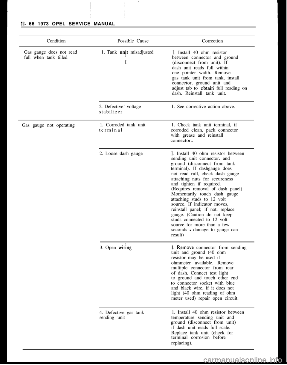
ll- 66 1973 OPEL SERVICE MANUALi
ConditionPossible CauseCorrection
Gas gauge does not read
full when tank tilled1. Tank unit misadjusted1. Install 40 ohm resistor
between connector and ground
I
(disconnect from unit). If
dash unit reads full within
one pointer width. Remove
/
Igas tank unit from tank, install
connector, ground unit and
adjust tab to obtairi full reading on
dash. Reinstall tank unit.
2. Defective’ voltage
stabilizer1. See corrective action above.
Gas gauge not operating1. Corroded tank unit
terminal I1. Check tank unit terminal, if
corroded clean, pack connector
with grease and reinstall
connector..
2. Loose dash gauge
!
1. Install 40 ohm resistor between
sending unit connector. and
ground (disconnect from tank
terminal). If dashgauge does
not read rull, check dash gauge
attaching nuts for secureness
and tighten if required.
(Requires removal of dash panel)
Momentarily touch dash gauge
attaching studs to 12 volt
source. If indicator moves,
reinstall panel; if not, replace
gauge. (Caution do not keep
studs connected to 12 volt
source for more than a few
seconds
- damage to gauge can
result)
3. Open
w&g1. Remove connector from sending
unit and ground (40 ohm
resistor may be used if
ohmmeter available. Remove
multiple connector from rear
of dash. Connect test light
to ground and touch other end
to connector socket with blue
and black wire, if it does not
light (40 ohm reading of ohm
meter used) repair open circuit.
4. Defective gas tank
sending unit1. Install 40 ohm resistor between
temperature sending unit and
ground (disconnect from unit)
if dash unit reads full scale.
Replace tank unit (check for
terminal corrosion before
replacing).
Page 88 of 625
I
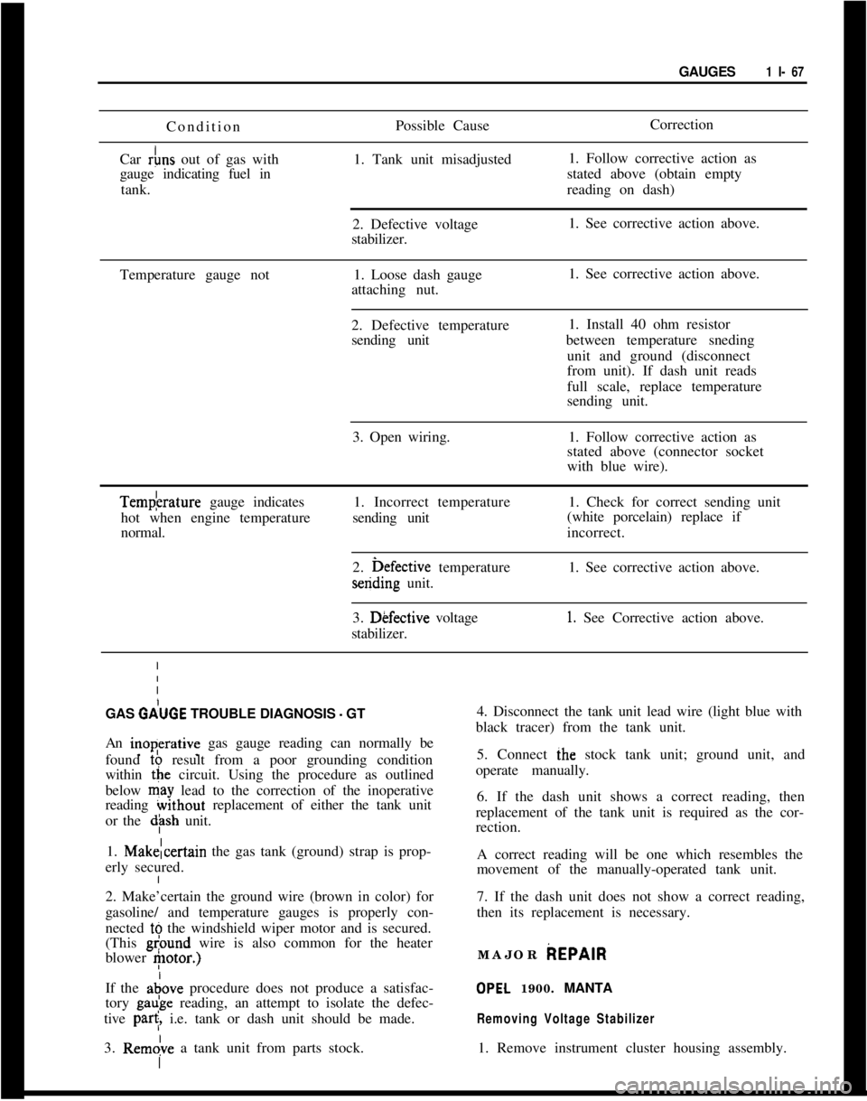
GAUGES1 I- 67I
I Condition
Car
&s out of gas with
gauge indicating fuel in
tank. 1
I
I
I
I
IPossible Cause
1. Tank unit misadjusted
2. Defective voltage
stabilizer.Correction
1. Follow corrective action as
stated above (obtain empty
reading on dash)
1. See corrective action above.
Temperature gauge not1. Loose dash gauge1. See corrective action above.
Iattaching nut.
I
I
I2. Defective temperature1. Install 40 ohm resistor
Isending unitbetween temperature sneding
Iunit and ground (disconnect
I
from unit). If dash unit reads
I
full scale, replace temperature
Isending unit.
I
I
I3. Open wiring.1. Follow corrective action as
Istated above (connector socket
Iwith blue wire).Tempkrature gauge indicates
hot when engine temperature1. Incorrect temperature1. Check for correct sending unit
sending unit
normal.(white porcelain) replace if
incorrect.
2. i>efective temperaturesending unit.1. See corrective action above.
3. Dkfective voltage
stabilizer.
1. See Corrective action above.
GAS
GdUGE TROUBLE DIAGNOSIS - GT4. Disconnect the tank unit lead wire (light blue with
black tracer) from the tank unit.
An inoperative gas gauge reading can normally be
found to result from a poor grounding condition
within the circuit. Using the procedure as outlined
below may lead to the correction of the inoperative
reading without replacement of either the tank unit
or the
dph unit.5. Connect ihe stock tank unit; ground unit, and
operate manually.
6. If the dash unit shows a correct reading, then
replacement of the tank unit is required as the cor-
rection.
1. Makelcertain the gas tank (ground) strap is prop-
erly secured.A correct reading will be one which resembles the
movement of the manually-operated tank unit.
2. Make’certain the ground wire (brown in color) for
gasoline/ and temperature gauges is properly con-
nected tb the windshield wiper motor and is secured.
(This
gl?ound wire is also common for the heater
blower
etor.)7. If the dash unit does not show a correct reading,
then its replacement is necessary.
If the adove procedure does not produce a satisfac-
tory gaube reading, an attempt to isolate the defec-
tive
par<, i.e. tank or dash unit should be made.
3. Rem&e a tank unit from parts stock.MAJOR
AEPAIR
OPEL 1900. MANTA
Removing Voltage Stabilizer1. Remove instrument cluster housing assembly.
Page 158 of 625
SEATS, INTERIOR TRIM AND HEADLININGZG-35
2. Push off side panel trim pad. Trim pad is held in
position by a retaining button.
REMOVAL AND INSTALLATIONOF HEADLINING
Removal
1. Disconnect battery.
2. Lift out rear seat cushion (sedans only).
3. From trunk area, loosen tabs holding cardboard
against rear seat cross brace and lift out cardboard
(sedans only).
4. Pry up two tabs holding lower portion of rear seat
back in position, swing back of seat forward and lift
out (sedans only).
5. From trunk area pry out parcel shelf plastic retain-
ers and lift out parcel shelf (sedans only).
6. Remove rear-view mirror, sun visors, interior
lamp, assist straps and coat hooks. Remove front and
rear windows on all but Wagon Models. On Wagons,
remove the front window and the quarter windows.
7. Work door opening pinchweld finishing strip
away from pinchweld as far as necessary to expose
edge of headlining.
8. Start at: left or right windshield pillar and pry
headlining loose.
9. Roll back headlining to expose metal tabs securing
headlining listing wire to roof and unhook headhn-
ing front listing wire from metal tabs using a blunt
edge tool.
10. Pull loose the edges of headlining cemented to
door openings, rear quarter window openings, rear
quarter pillar and from under rear window rubber
channel. On rear quarter pillars, slightly bend down
cardboard of rear quarter trim pad to facilitate re-
moval. During removal, special care should be taken
not to tear headlining at seams.
11. After edges of headlining have been pulled loose,
tilt remaining listing wires with headlining forward
or rearward and pull listing wires free from side roof
rails. Lift out headlining and listing wires.
Installation1. Check secureness of noise insulation pad on inside
of roof panel and recement as necessary using asphalt
cement. If headlining is to be replaced, insert listing
wires into headlining according to their markings.
Progressing from the front listing wire to the rear
wire, the left ends of the wires are color coded as
follows:1st listing wire
- No marking, wire is thinner than
other wires
2nd listing wire
- Red
3rd listing wire
- Blue
4th listing wire
_ Green
5th listing wire
- Brown
6th listing wire
- White
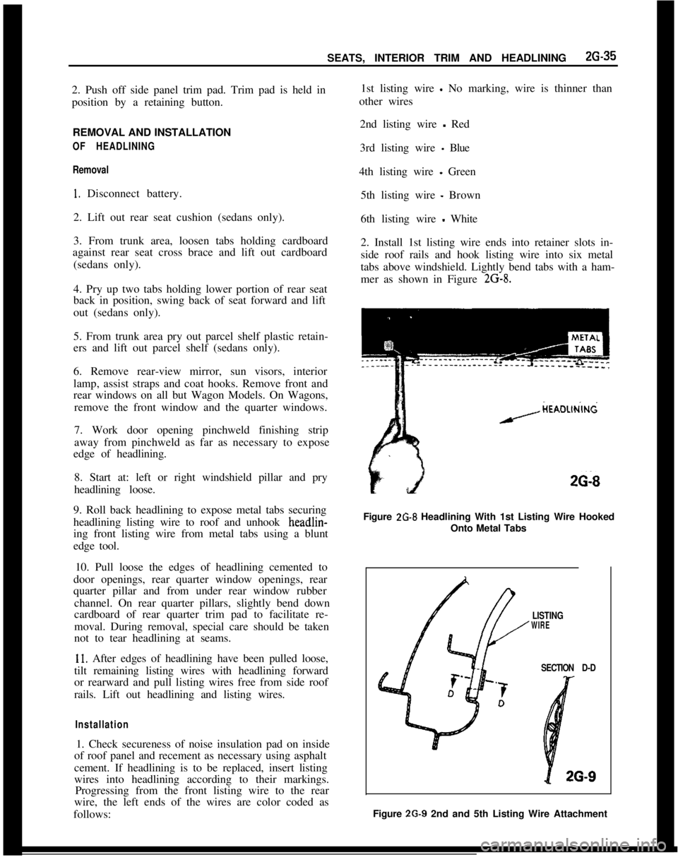
2. Install 1st listing wire ends into retainer slots in-
side roof rails and hook listing wire into six metal
tabs above windshield. Lightly bend tabs with a ham-
mer as shown in Figure
2G-8.
HEAOLlN’lNdA-----
26-8Figure
2G-8 Headlining With 1st Listing Wire Hooked
Onto Metal Tabs
LISTINGWIRE
SECTIOND-D
4 26-9Figure 2G-9 2nd and 5th Listing Wire Attachment
Page 365 of 625
7A- 41973 dPEL SERVICE MANUALConditionPossible CauseCorrectionHeat-blued driven plate
and pressure plate
assembly.
1. Improper pedal1. Replace only driven plate, and
adjustment.adjust clutch pedal and cable.
Grab and chatter with
oil present on clutch
assembly.1. Oil leak.1. Correct oil leakage, clean
pressure plate in solvent, replace
driven plate and adjust pedal lash.
MAINTENANCE AND ADJUSTMENTS
CLUTCH LASH ADJUSTMENT
GTPedal lash, free pedal travel must be adjusted occa-
sionally to compensate for normal wear of the clutch
facings. As the driven plate wears thinner, pedal lash
decreases. Adjust clutch pedal free travel only with
ball stud located on right side of clutch housing if
cable length is not to be changed. To adjust pedal
lash proceed as follows:
1. Loosen lock nut on ball stud end located to the
right of the transmission on the clutch housing. Posi-
tion ball stud so that the outer end protrudes 3/4
inches out of housing and finger tighten lock nut. See
Figures
7A-1 and 7A-6.
2. Adjust ball stud, pivoting clutch release fork, to
obtain 3/4 to
l-1/4 inches pedal lash, free pedal. See
Figure 7A-6.
Opel 1900 and MantaThe clutch actuation works without clutch pedal free
travel. A readjustment of the clutch is only required
if the indicator lamp at the instrument panel lights
up.In synchronism with the gradual wear of the clutch
linings the clutch pedal travels from its basic adjust-
ment position upwards,
ie., towards driver. If the
clutch lining wear has reached such an extent that
the clutch pedal rests against switch, the indicator
lamp at the instrument panel lights up.
This is an indication that the clutch pedal position
has to be corrected to ensure proper clutch operat-
ion.
To
&~sure proper clutch operation, observe the fol-
lowing adjustment instructions.. For all adjustment
dimensions, refer to Figure 7A-7.
1. If the parking brake is provided with an indicator
lamp, the parking brake has to be disengaged, other-wise the same indicator lamp as for the clutch lights
UP.2. Carry out adjustment only with ball stud on clutch
housing whereby the distance (Item 20, Figure 7A-7)
between clutch housing contacting surface and
clutch release lever has to be adjusted in the rear to
4
l/4 inches.
Clutch Control Cable Adjustment(Only on
Installation of a New Clutch Disc or
Bowden
Control Wire)
GT1. Adjust ball stud so that outer end protrudes ap-
proximately 3/4 inches out of clutch housing.
2. Adjust distance between release lever and clutch
housing face at eye for control cable to approxi-
mately 4
l/4 inches. See Figure 7A-6. Hold cable in
this position and place E-ring two grooves ahead of
washer on rubber grommet. Clutch pedal free travel
is now between 3/4 and 1
l/4 inches and clutch
release bearing has proper clearance from pressure
plate.
Opel 1900 and Manta1. Adjust ball stud on clutch housing to basic dimen-
sion of approximately 3/4 inch. With lower end ofbowden control wire unhooked, push clutch release
lever towards the front so that the clutch release
bearing rests against clutch spring. Now, adjust ball
stud so that the dimension (Item 20, Figure
7A-7)between clutch housing contacting surface and
clutch release lever amounts in the rear to 4
l/4
inches.2. Pull reattached bowden control wire out of dash
panel so that clutch pedal rests against switch (in-
dicator lamp lights up).
3. In this position, install lockwasher at upper con-
trol wire attachment three grooves towards the front,
thereby completing control wire adjustment.
Page 490 of 625
AUTOMATIC TRANSMISSION 7C-129
4. Install reverse clutch cushion plate (wave washer)2. Insert guide pin into oil pump for alignment of
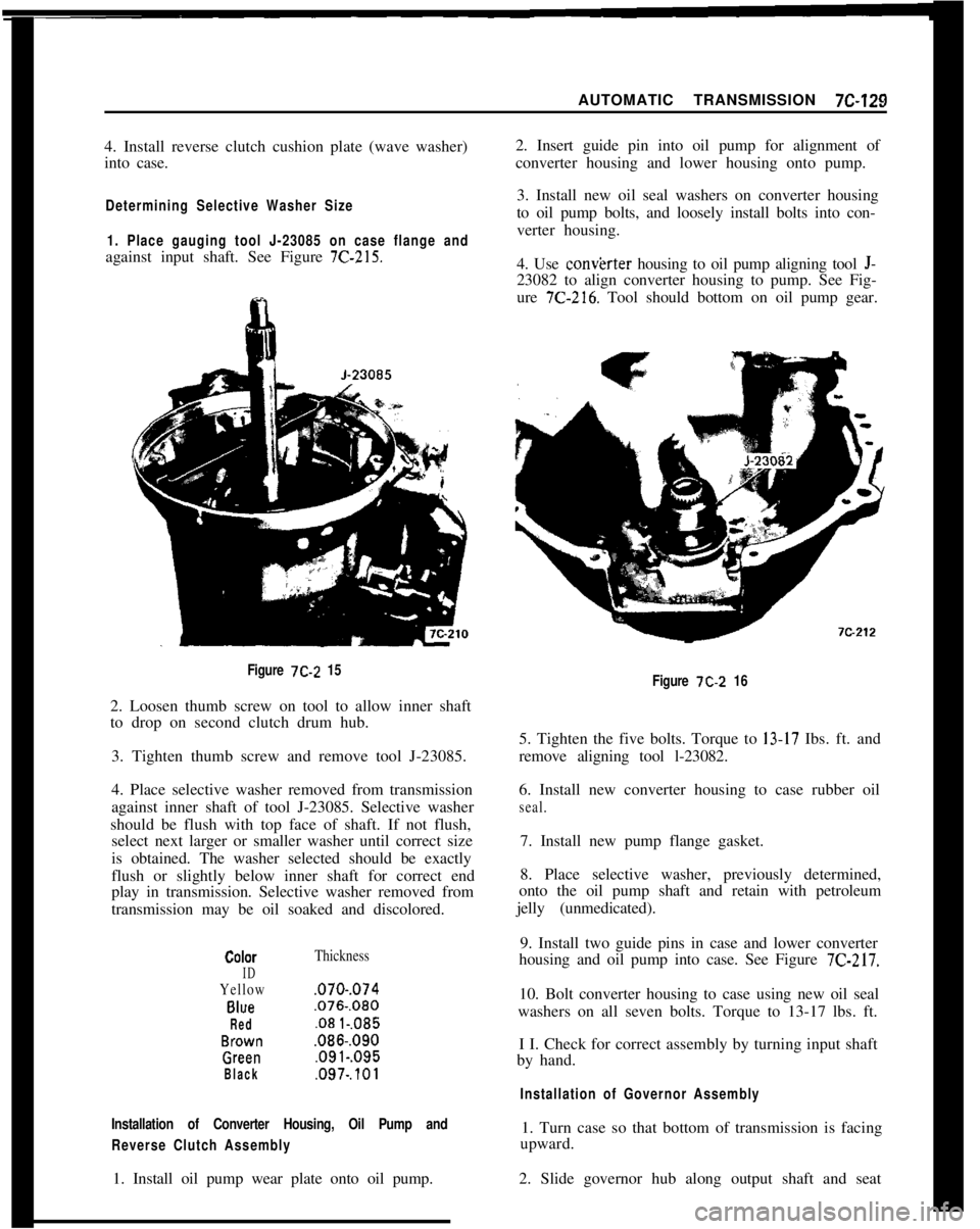
into case.converter housing and lower housing onto pump.Determining Selective Washer Size
1. Place gauging tool J-23085 on case flange andagainst input shaft. See Figure
7C-215.3. Install new oil seal washers on converter housing
to oil pump bolts, and loosely install bolts into con-
verter housing.
4. Use convkrter housing to oil pump aligning tool J-23082 to align converter housing to pump. See Fig-
ure
7C-216. Tool should bottom on oil pump gear.
Figure 7C-2 152. Loosen thumb screw on tool to allow inner shaft
to drop on second clutch drum hub.
3. Tighten thumb screw and remove tool J-23085.
4. Place selective washer removed from transmission
against inner shaft of tool J-23085. Selective washer
should be flush with top face of shaft. If not flush,
select next larger or smaller washer until correct size
is obtained. The washer selected should be exactly
flush or slightly below inner shaft for correct end
play in transmission. Selective washer removed from
transmission may be oil soaked and discolored.
CObX
ID
Yellow
Blue
Red
BVSNIl
GPX3”
Black
Thickness,070.,074,076.,080
.08 l-.085,086.,090,091.,095
,097.,101
Installation of Converter Housing, Oil Pump and
Reverse Clutch Assembly1. Turn case so that bottom of transmission is facing
upward.
1. Install oil pump wear plate onto oil pump.2. Slide governor hub along output shaft and seat
Figure 7C-2 165. Tighten the five bolts. Torque to
13-17 Ibs. ft. and
remove aligning tool l-23082.
6. Install new converter housing to case rubber oil
seal.7. Install new pump flange gasket.
8. Place selective washer, previously determined,
onto the oil pump shaft and retain with petroleum
jelly (unmedicated).
9. Install two guide pins in case and lower converter
housing and oil pump into case. See Figure
7C-217.10. Bolt converter housing to case using new oil seal
washers on all seven bolts. Torque to 13-17 lbs. ft.
I I. Check for correct assembly by turning input shaft
by hand.
Installation of Governor Assembly
Page 512 of 625
HEATER SYSTEM. GT9A- 3
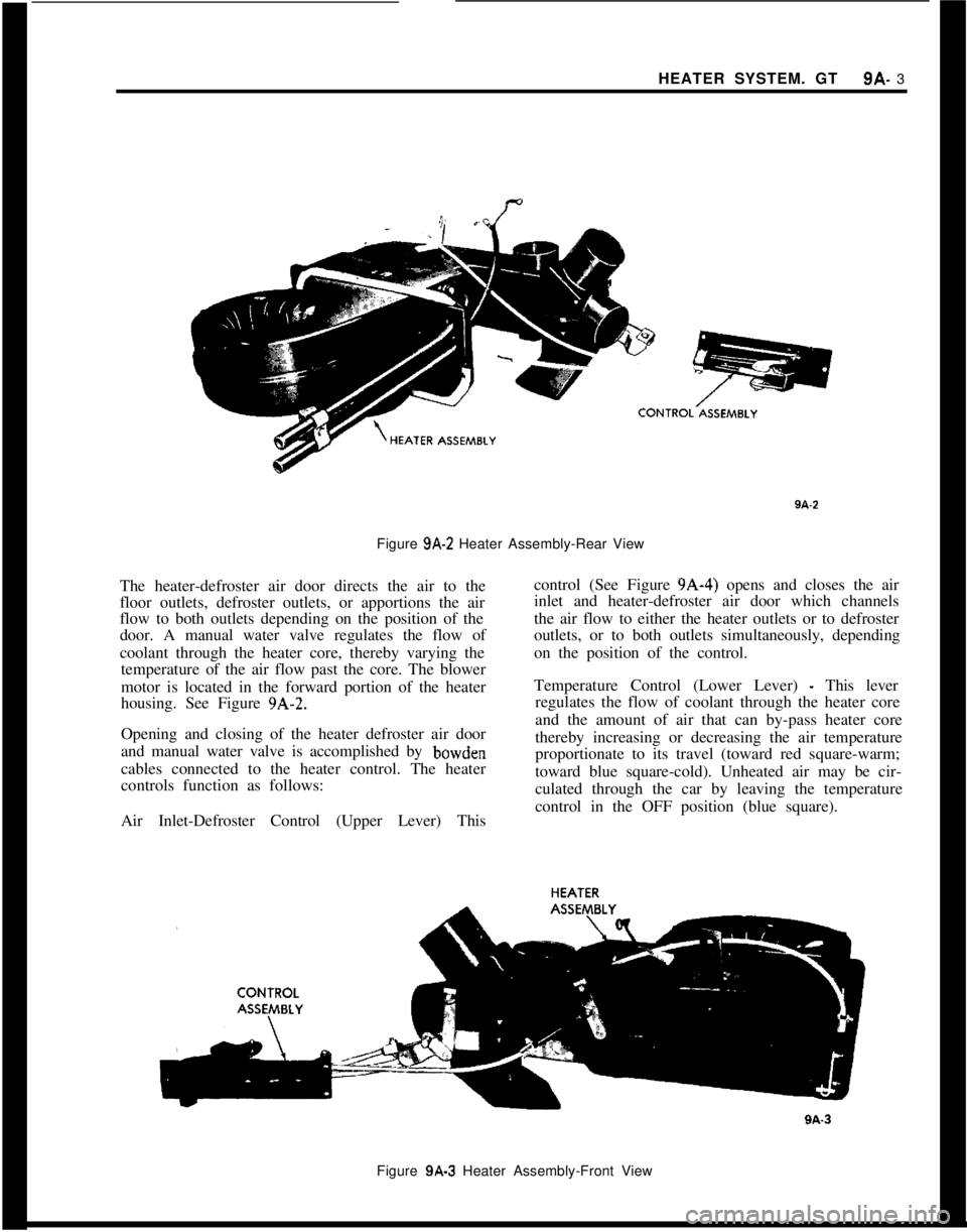
Figure 9A-‘2 Heater Assembly-Rear View
The heater-defroster air door directs the air to the
floor outlets, defroster outlets, or apportions the air
flow to both outlets depending on the position of the
door. A manual water valve regulates the flow of
coolant through the heater core, thereby varying the
temperature of the air flow past the core. The blower
motor is located in the forward portion of the heater
housing. See Figure 9A-2.
Opening and closing of the heater defroster air door
and manual water valve is accomplished by bowden
cables connected to the heater control. The heater
controls function as follows:
Air Inlet-Defroster Control (Upper Lever) Thiscontrol (See Figure 9A-4) opens and closes the air
inlet and heater-defroster air door which channels
the air flow to either the heater outlets or to defroster
outlets, or to both outlets simultaneously, depending
on the position of the control.
Temperature Control (Lower Lever)
- This lever
regulates the flow of coolant through the heater core
and the amount of air that can by-pass heater core
thereby increasing or decreasing the air temperature
proportionate to its travel (toward red square-warm;
toward blue square-cold). Unheated air may be cir-
culated through the car by leaving the temperature
control in the OFF position (blue square).
Figure 9A-3 Heater Assembly-Front View
Page 548 of 625
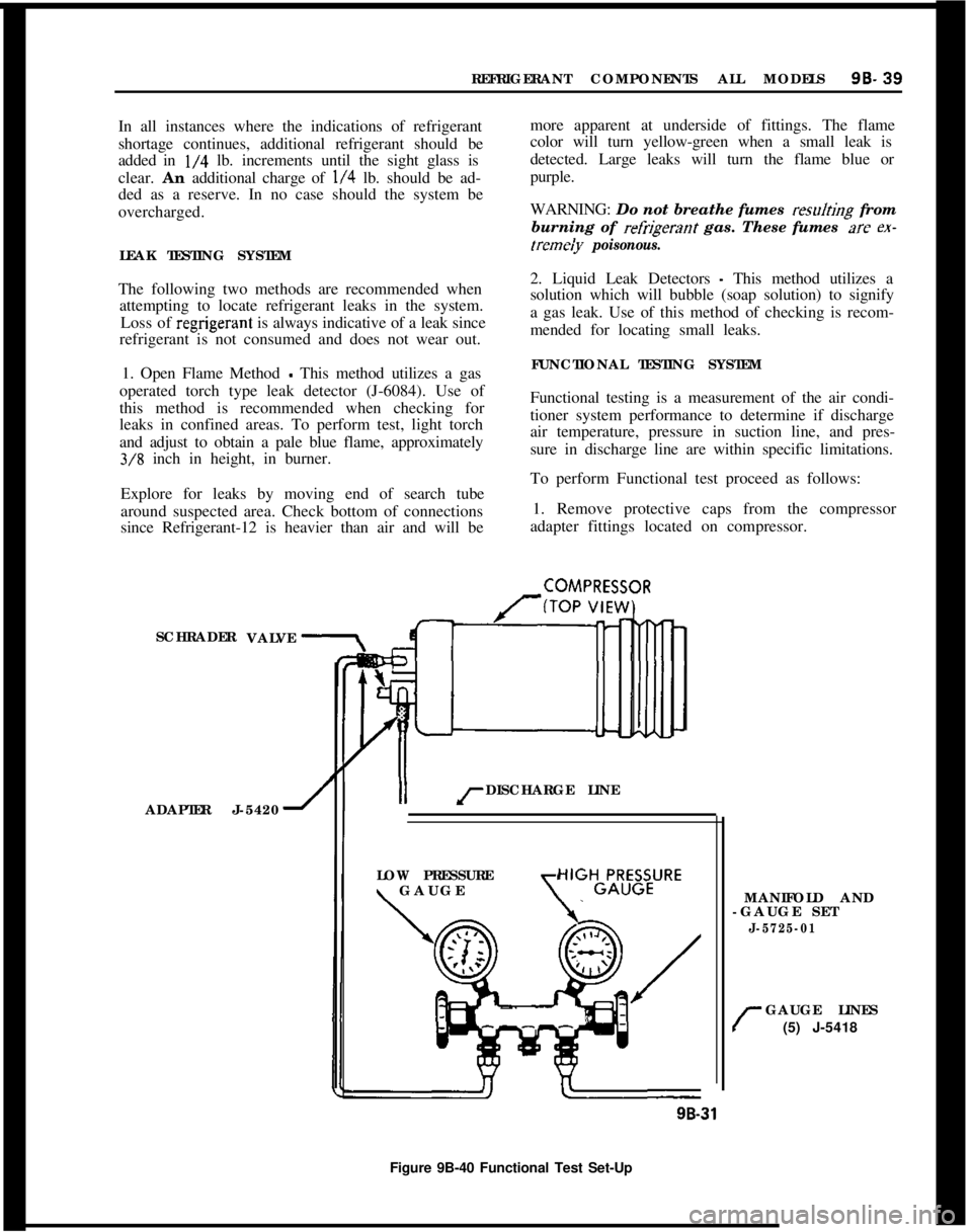
REFRIGERANT COMPONENTS ALL MODELS96-39
In all instances where the indications of refrigerant
shortage continues, additional refrigerant should be
added in
l/4 lb. increments until the sight glass is
clear.
An additional charge of l/4 lb. should be ad-
ded as a reserve. In no case should the system be
overcharged.
LEAK TESTING SYSTEM
The following two methods are recommended when attempting to locate refrigerant leaks in the system.
Loss of
regrigerant is always indicative of a leak since
refrigerant is not consumed and does not wear out.
1. Open Flame Method
- This method utilizes a gas
operated torch type leak detector (J-6084). Use of
this method is recommended when checking for
leaks in confined areas. To perform test, light torch
and adjust to obtain a pale blue flame, approximately
3/8 inch in height, in burner.
Explore for leaks by moving end of search tube
around suspected area. Check bottom of connections
since Refrigerant-12 is heavier than air and will be more apparent at underside of fittings. The flame
color will turn yellow-green when a small leak is
detected. Large leaks will turn the flame blue or
purple.
WARNING:
Do not breathe fumes resdting from
burning of
refrigerant gas. These fumes az ex-
tremeiy poisonous.
2. Liquid Leak Detectors - This method utilizes a
solution which will bubble (soap solution) to signify
a gas leak. Use of this method of checking is recom-
mended for locating small leaks.
FUNCTIONAL TESTING SYSTEM
Functional testing is a measurement of the air condi-
tioner system performance to determine if discharge
air temperature, pressure in suction line, and pres-
sure in discharge line are within specific limitations.
To perform Functional test proceed as follows:
1. Remove protective caps from the compressor
adapter fittings located on compressor.
SCHRADER
ADAPTER J-5420
1II rDISCHARGE LINE
COMPRESSOR
VALVE
LOW PRESSURE
\ GAUGE\
HIGHGLR;B;URE
MANIFOLD AND
-GAUGE SET
J-5725-01
r
GAUGE LINES
(5) J-5418
9B-31
Figure 9B-40 Functional Test Set-Up
Page 597 of 625
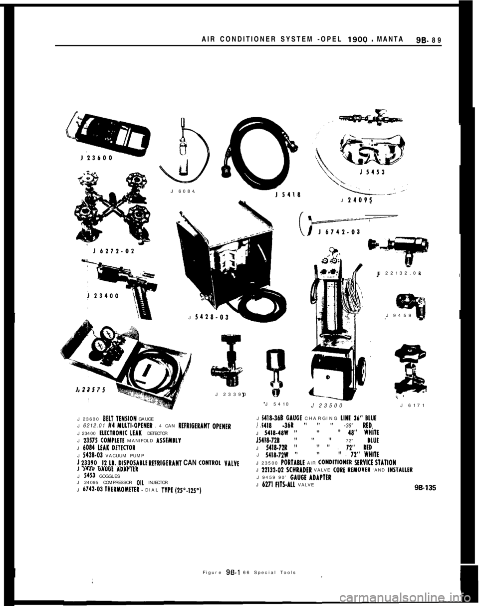
AIR CONDITIONER SYSTEM -OPEL 1900 - MANTASB- 89
cJ 6084
J
14OVSJ
5428.03
,J 23390
J 23600 BELT IENSION GAUGE
J 6212.01 #4 MlJLTI.OPtNtR . 4 CAN RtFRIGtRANT OPENER
J 23400
tlKlRONIC LEAK DETECTOR
J 23575 COMPLHE MANIFOLD ASSfYBLY
J 6034 LEAK WtClORJ 5418-03 VACUUM PUMP
! ?!!~O~!~~~..~I~poIIRL~ REFRIGERANT CAN CONIROL VALVEI WI" 6A"Gt ADAPTEK
J 5453 GOGGLES
J 24095 COMPRESSOR OIL INJECTOR
J 6742.03 IHtRMOMETER
- DIAL TYPE (2S”.lZ5~)J 22132.02
I
J 9459
1J 5410
J 23500J 6171
141%360 GAUGt CHARGING LINE 36” BLUEi418 -36R ” ” ” -36” RED, J!I I, .J 5418.48W ””” 48” WHIIEJ5418.728
” ” ” 72” BLUI
J 5418.72s ”” I’ . 11” RtD
J 5418.7ZW ””” . 72” WWllt
J 23500 PORlARLt AIR ~ONDIlIONtR SERVlCt STAllON
J 22132.D2 SCWRADER VALVE
J 6271 FIlS.ALL VALVE98136I
IFigure 96-l 66 Special Tools