OPEL VECTRA 1988 Service Repair Manual
Manufacturer: OPEL, Model Year: 1988, Model line: VECTRA, Model: OPEL VECTRA 1988Pages: 525, PDF Size: 58.26 MB
Page 211 of 525
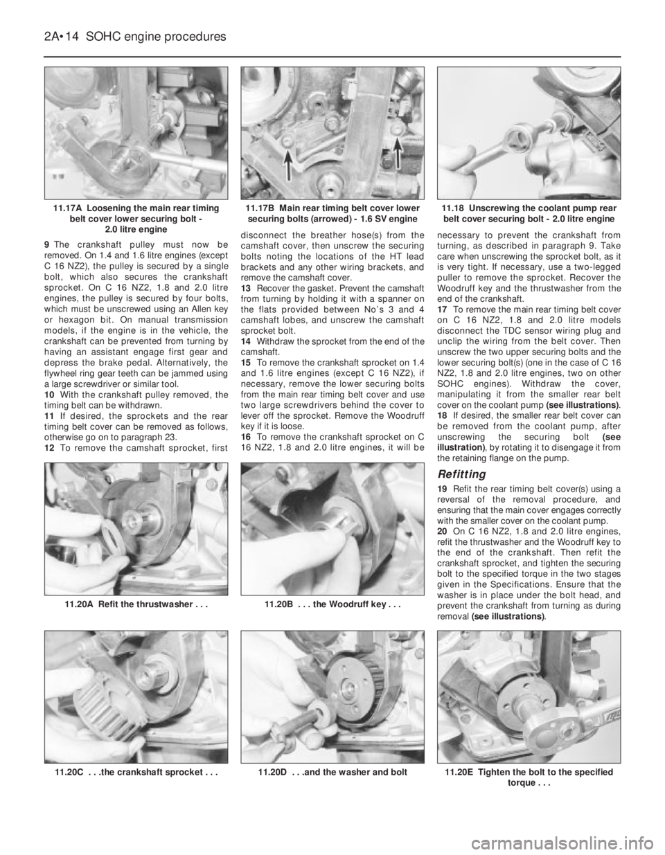
9The crankshaft pulley must now be
removed. On 1.4 and 1.6 litre engines (except
C 16 NZ2), the pulley is secured by a single
bolt, which also secures the crankshaft
sprocket. On C 16 NZ2, 1.8 and 2.0 litre
engines, the pulley is secured by four bolts,
which must be unscrewed using an Allen key
or hexagon bit. On manual transmission
models, if the engine is in the vehicle, the
crankshaft can be prevented from turning by
having an assistant engage first gear and
depress the brake pedal. Alternatively, the
flywheel ring gear teeth can be jammed using
a large screwdriver or similar tool.
10With the crankshaft pulley removed, the
timing belt can be withdrawn.
11If desired, the sprockets and the rear
timing belt cover can be removed as follows,
otherwise go on to paragraph 23.
12To remove the camshaft sprocket, firstdisconnect the breather hose(s) from the
camshaft cover, then unscrew the securing
bolts noting the locations of the HT lead
brackets and any other wiring brackets, and
remove the camshaft cover.
13Recover the gasket. Prevent the camshaft
from turning by holding it with a spanner on
the flats provided between No’s 3 and 4
camshaft lobes, and unscrew the camshaft
sprocket bolt.
14Withdraw the sprocket from the end of the
camshaft.
15To remove the crankshaft sprocket on 1.4
and 1.6 litre engines (except C 16 NZ2), if
necessary, remove the lower securing bolts
from the main rear timing belt cover and use
two large screwdrivers behind the cover to
lever off the sprocket. Remove the Woodruff
key if it is loose.
16To remove the crankshaft sprocket on C
16 NZ2, 1.8 and 2.0 litre engines, it will benecessary to prevent the crankshaft from
turning, as described in paragraph 9. Take
care when unscrewing the sprocket bolt, as it
is very tight. If necessary, use a two-legged
puller to remove the sprocket. Recover the
Woodruff key and the thrustwasher from the
end of the crankshaft.
17To remove the main rear timing belt cover
on C 16 NZ2, 1.8 and 2.0 litre models
disconnect the TDC sensor wiring plug and
unclip the wiring from the belt cover. Then
unscrew the two upper securing bolts and the
lower securing bolt(s) (one in the case of C 16
NZ2, 1.8 and 2.0 litre engines, two on other
SOHC engines). Withdraw the cover,
manipulating it from the smaller rear belt
cover on the coolant pump (see illustrations).
18If desired, the smaller rear belt cover can
be removed from the coolant pump, after
unscrewing the securing bolt (see
illustration), by rotating it to disengage it from
the retaining flange on the pump.
Refitting
19Refit the rear timing belt cover(s) using a
reversal of the removal procedure, and
ensuring that the main cover engages correctly
with the smaller cover on the coolant pump.
20On C 16 NZ2, 1.8 and 2.0 litre engines,
refit the thrustwasher and the Woodruff key to
the end of the crankshaft. Then refit the
crankshaft sprocket, and tighten the securing
bolt to the specified torque in the two stages
given in the Specifications. Ensure that the
washer is in place under the bolt head, and
prevent the crankshaft from turning as during
removal (see illustrations).
2A•14SOHC engine procedures
11.17A Loosening the main rear timing
belt cover lower securing bolt -
2.0 litre engine11.18 Unscrewing the coolant pump rear
belt cover securing bolt - 2.0 litre engine
11.20E Tighten the bolt to the specified
torque . . .11.20D . . .and the washer and bolt11.20C . . .the crankshaft sprocket . . .
11.20B . . . the Woodruff key . . .11.20A Refit the thrustwasher . . .
11.17B Main rear timing belt cover lower
securing bolts (arrowed) - 1.6 SV engine
Page 212 of 525
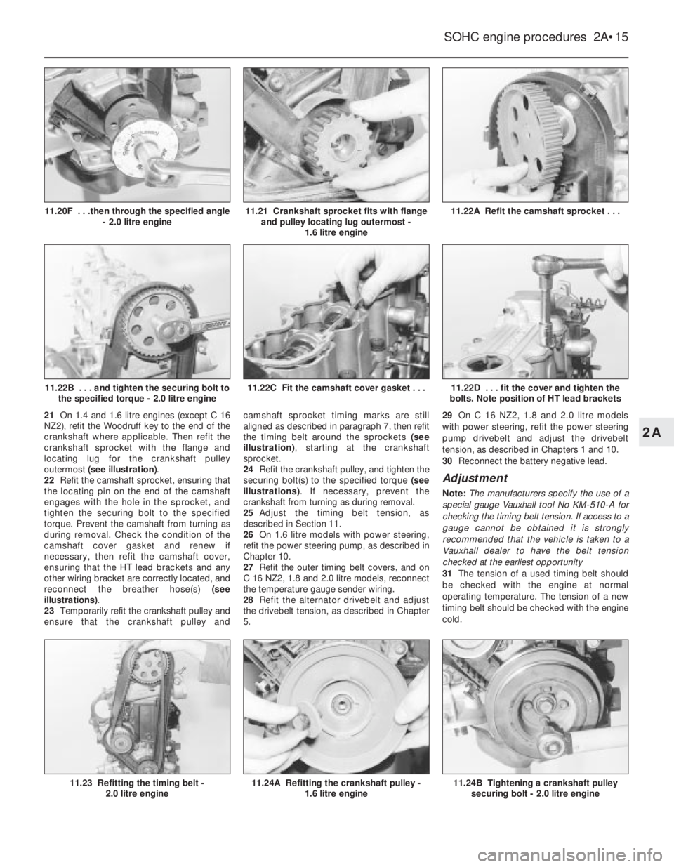
21On 1.4 and 1.6 litre engines (except C 16
NZ2), refit the Woodruff key to the end of the
crankshaft where applicable. Then refit the
crankshaft sprocket with the flange and
locating lug for the crankshaft pulley
outermost (see illustration).
22Refit the camshaft sprocket, ensuring that
the locating pin on the end of the camshaft
engages with the hole in the sprocket, and
tighten the securing bolt to the specified
torque. Prevent the camshaft from turning as
during removal. Check the condition of the
camshaft cover gasket and renew if
necessary, then refit the camshaft cover,
ensuring that the HT lead brackets and any
other wiring bracket are correctly located, and
reconnect the breather hose(s) (see
illustrations).
23Temporarily refit the crankshaft pulley and
ensure that the crankshaft pulley andcamshaft sprocket timing marks are still
aligned as described in paragraph 7, then refit
the timing belt around the sprockets (see
illustration), starting at the crankshaft
sprocket.
24Refit the crankshaft pulley, and tighten the
securing bolt(s) to the specified torque (see
illustrations). If necessary, prevent the
crankshaft from turning as during removal.
25Adjust the timing belt tension, as
described in Section 11.
26On 1.6 litre models with power steering,
refit the power steering pump, as described in
Chapter 10.
27Refit the outer timing belt covers, and on
C 16 NZ2, 1.8 and 2.0 litre models, reconnect
the temperature gauge sender wiring.
28Refit the alternator drivebelt and adjust
the drivebelt tension, as described in Chapter
5.29On C 16 NZ2, 1.8 and 2.0 litre models
with power steering, refit the power steering
pump drivebelt and adjust the drivebelt
tension, as described in Chapters 1 and 10.
30Reconnect the battery negative lead.
Adjustment
Note: The manufacturers specify the use of a
special gauge Vauxhall tool No KM-510-A for
checking the timing belt tension. If access to a
gauge cannot be obtained it is strongly
recommended that the vehicle is taken to a
Vauxhall dealer to have the belt tension
checked at the earliest opportunity
31The tension of a used timing belt should
be checked with the engine at normal
operating temperature. The tension of a new
timing belt should be checked with the engine
cold.
SOHC engine procedures 2A•15
11.22A Refit the camshaft sprocket . . .
11.24B Tightening a crankshaft pulley
securing bolt - 2.0 litre engine11.24A Refitting the crankshaft pulley -
1.6 litre engine11.23 Refitting the timing belt -
2.0 litre engine
11.22D . . . fit the cover and tighten the
bolts. Note position of HT lead brackets11.22C Fit the camshaft cover gasket . . .11.22B . . . and tighten the securing bolt to
the specified torque - 2.0 litre engine
11.21 Crankshaft sprocket fits with flange
and pulley locating lug outermost -
1.6 litre engine11.20F . . .then through the specified angle
- 2.0 litre engine
2A
Page 213 of 525
32Release the securing clips and remove the
main outer timing belt cover, then unclip the
smaller outer timing belt cover from the
coolant pump.
33Turn the crankshaft through at least
quarter of a turn clockwise using a socket or
spanner on the crankshaft sprocket bolt.
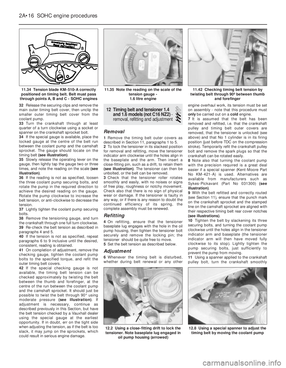
34If the special gauge is available, place the
locked gauge at the centre of the belt run
between the coolant pump and the camshaft
sprocket. The gauge should locate on the
timing belt (see illustration).
35Slowly release the operating lever on the
gauge, then lightly tap the gauge two or three
times, and note the reading on the scale (see
illustration).
36If the reading is not as specified, loosen
the three coolant pump securing bolts, and
rotate the pump in the required direction to
achieve the desired reading on the gauge.
Rotate the pump clockwise to increase the
belt tension, or anti-clockwise to decrease the
tension.
37Lightly tighten the coolant pump securing
bolts.
38Remove the tensioning gauge, and turn
the crankshaft through one full turn clockwise.
39Re-check the belt tension as described in
paragraphs 4 and 5.
40If the tension is not as specified, repeat
paragraphs 6 to 9 inclusive until the desired,
consistent, reading is obtained.
41On completion of adjustment, remove the
checking gauge, tighten the coolant pump
bolts to the specified torque, and refit the
outer timing belt covers.
42If the special checking gauge is not
available, the timing belt tension can be
checked approximately by twisting the belt
between the thumb and forefinger, at the
centre of the run between the coolant pump
and the camshaft sprocket. It should just be
possible to twist the belt through 90°using
moderate pressure (see illustration). If
adjustment is necessary, continue as
described previously in this Section, but have
the belt tension checked by a Vauxhall dealer
using the special gauge at the earliest
opportunity. If in doubt, err on the tight side
when adjusting the tension, as if the belt is too
slack, it may jump on the sprockets, which
could result in serious engine damage.12Timing belt and tensioner 1.4
and 1.6 models (not C16 NZ2) -
removal, refitting and adjustment
3
Removal
1Remove the timing belt outer covers as
described in Section 11, paragraphs 1 to 5.
2To lock the tensioner in its slackest position
for removal and refitting, move the tensioner
indicator arm clockwise until the holes align in
the baseplate and the arm. Then insert a
close-fitting pin, such as a drift, to retain them
(see illustration). The tensioner can then be
unbolted, or the belt can be removed.
3Check that the tensioner roller rotates
smoothly and easily, with no noises or signs
of free play, roughness or notchy movement.
Check also that there is no sign of physical
wear or damage. If the tensioner is faulty in
any way, or if there is any reason to doubt the
continued efficiency of its spring, the
complete assembly must be renewed.
Refitting
4On refitting, ensure that the tensioner
baseplate lug engages with the hole in the oil
pump housing, then tighten the tensioner bolt
securely and remove the locking pin; the
tensioner should be quite free to move.
5Set the belt tension as described below.
Adjustment
6Whenever the timing belt is disturbed,
whether during belt renewal or any otherengine overhaul work, its tension must be set
on assembly - note that this procedure must
only be carried out on a cold engine.
7It is assumed that the belt has been
removed and refitted, i.e. that the crankshaft
pulley and timing belt outer covers are
removed, that the tensioner is unlocked (see
above) and that No 1 cylinder is in its firing
position (just before TDC on the compression
stroke). Temporarily refit the crankshaft pulley
bolt and remove the spark plugs so that the
crankshaft can be rotated easily.
8Note also that turning the coolant pump
with the precision required is a great deal
easier if a special spanner (Kent-Moore Part
No KM-421-A) is used. Alternatives are
available from manufacturers such as
Sykes-Pickavant (Part No 031300) (see
illustration).
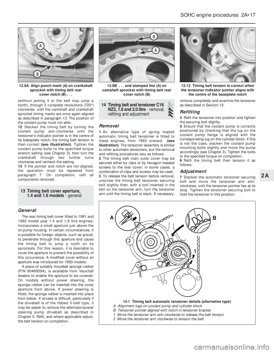
9With the belt refitted and correctly routed
(see Section 11), ensure that the punch mark
on the crankshaft sprocket and the stamped
line on the camshaft sprocket are aligned with
their respective timing belt rear cover notches
(see illustrations).
10Tighten the belt by slackening its three
securing bolts, and turning the coolant pump
clockwise until the holes align in the tensioner
indicator arm and baseplate (the tensioner
indicator arm will then have moved fully
clockwise to its stop). Lightly tighten the
pump securing bolts, just sufficiently to
prevent the pump from moving.
11Using a spanner applied to the crankshaft
pulley bolt, turn the crankshaft smoothly
2A•16SOHC engine procedures
11.34 Tension blade KM-510-A correctly
positioned on timing belt. Belt must pass
through points A, B and C - SOHC engines11.42 Checking timing belt tension by
twisting belt through 90º between thumb
and forefinger
12.8 Using a special spanner to adjust the
timing belt by moving the coolant pump12.2 Using a close-fitting drift to lock the
tensioner. Note baseplate lug engaged in
oil pump housing (arrowed)
11.35 Note the reading on the scale of the
tension gauge -
1.6 litre engine
Page 214 of 525
(without jerking it or the belt may jump a
tooth), through 2 complete revolutions (720°)
clockwise, until the camshaft and crankshaft
sprocket timing marks are once again aligned
as described in paragraph 13. The position of
the coolant pump must not alter.
12Slacken the timing belt by turning the
coolant pump anti-clockwise until the
tensioner’s indicator pointer is in the centre of
its baseplate notch; the timing belt tension is
then correct (see illustration). Tighten the
coolant pump bolts to the specified torque
wrench setting (see Chapter 3), then turn the
crankshaft through two further turns
clockwise and recheck the setting.
13If the pointer and notch are not aligned,
the operation must be repeated from
paragraph 7. On completion, refit all
components removed.
13Timing belt cover aperture,
1.4 and 1.6 models - general
General
The rear timing belt cover fitted to 1991 and
1992 model year 1.4 and 1.6 litre engines,
incorporates a small aperture just above the
oil pump housing. In certain circumstances, it
is possible for foreign objects, such as gravel,
to penetrate through this aperture and cause
the timing belt to jump a tooth on its
sprockets. For this reason, it is desirable to
cover the aperture to prevent the possibility of
this occurrence. A modified cover without an
aperture was introduced for 1993 models.
A piece of suitably moulded sponge rubber
(P/N 90469594), is available from Vauxhall
dealers to enable the aperture to be covered.
On models without power steering, the
sponge rubber can be inserted into the cover
aperture from above. If power steering is
fitted, the sponge rubber is inserted into place
from below. If access is difficult, particularly if
the drivebelt is of the ribbed V-belt type, it
may be easier to remove the alternator/power
steering pump drivebelt as described in
Chapter 5. Refit, and where applicable adjust,
the belt tension on completion.
14Timing belt and tensioner C16
NZ2, 1.8 and 2.0 litre - removal,
refitting and adjustment
3
Removal
1An alternative type of spring loaded
automatic timing belt tensioner is fitted to
these engines, from 1993 onward (see
illustration). The tensioner assembly is similar
to other automatic tensioners, but the removal
and refitting procedures vary as follows.
2The timing belt main outer cover may be
secured either by clips or by hexagon-headed
screws to the rear cover; in some cases, a
combination of clips and screws may be used.
3To release the belt tension before removal,
unscrew the timing belt tensioner securing
bolt slightly then, with a tool inserted in the
slot on the tensioner arm, turn the tensioner
arm until the timing belt is slack. If necessary,remove completely and examine the tensioner
as described in Section 12.
Refitting
4Refit the tensioner into position and tighten
the securing bolt slightly.
5Ensure that the coolant pump is correctly
positioned by checking that the lug on the
coolant pump flange is aligned with the
corresponding lug on the cylinder block. If this
is not the case, slacken the coolant pump
mounting bolts slightly and move the pump
accordingly (see Chapter 3). Tighten the bolts
to the specified torque on completion.
6Refit the timing belt then tension it as
follows.
Adjustment
7Slacken the automatic tensioner securing
bolt and move the tensioner arm anti-
clockwise, until the tensioner pointer lies at its
stop. Tighten the tensioner securing bolt to
hold the tensioner in this position.
SOHC engine procedures 2A•17
12.12 Timing belt tension is correct when
the tensioner indicator pointer aligns with
the centre of the baseplate notch12.9B . . . and stamped line (A) on
camshaft sprocket with timing belt rear
cover notch (B)12.9A Align punch mark (A) on crankshaft
sprocket with timing belt rear
cover notch (B) . . .
2A
14.1 Timing belt automatic tensioner details (alternative type)
A Alignment lugs on coolant pump and cylinder block
B Tensioner pointer aligned with notch in tensioner bracket
1 Move the tensioner arm anti-clockwise to release the belt tension
2 Move the tensioner arm clockwise to tension the belt
Page 215 of 525
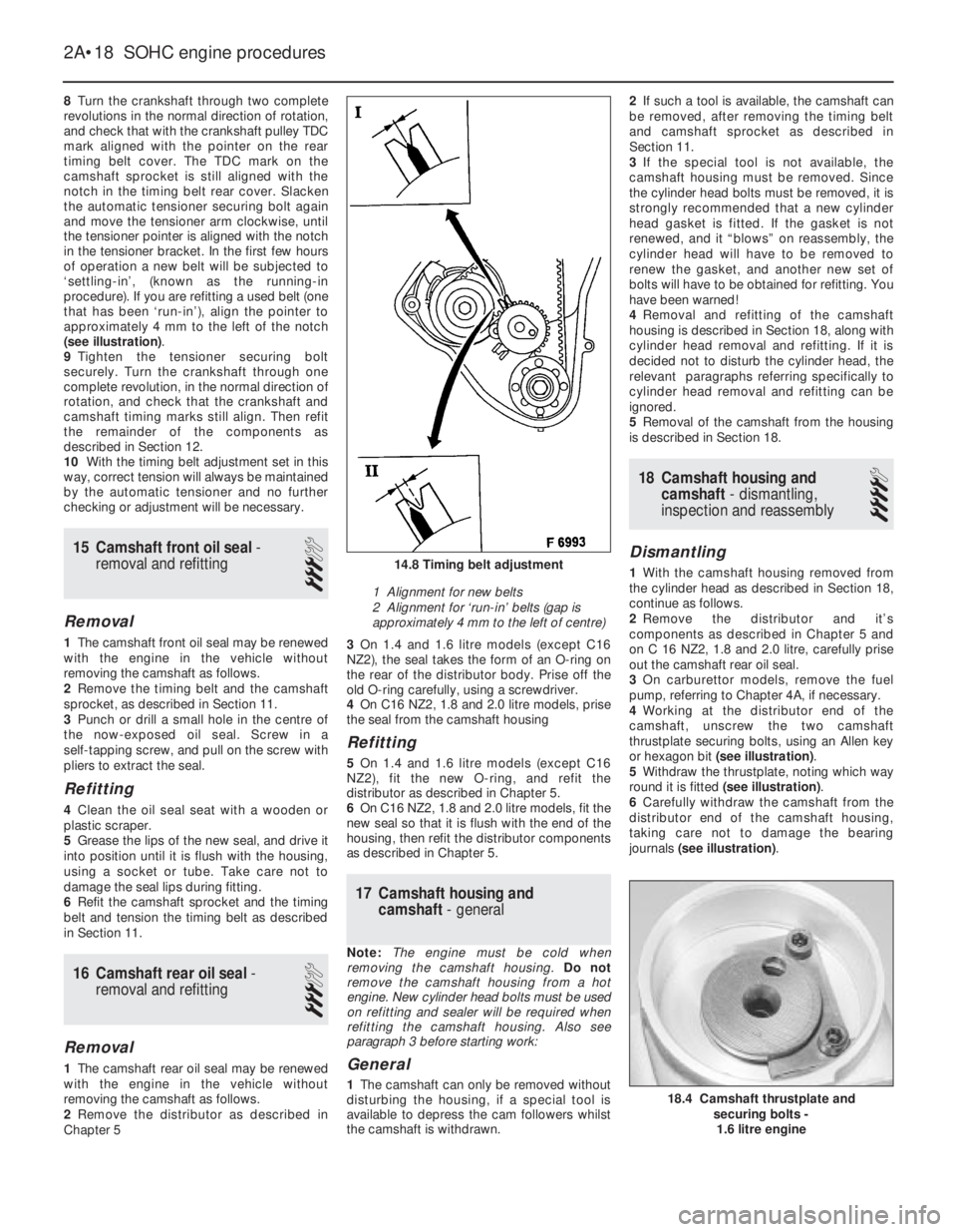
8Turn the crankshaft through two complete
revolutions in the normal direction of rotation,
and check that with the crankshaft pulley TDC
mark aligned with the pointer on the rear
timing belt cover. The TDC mark on the
camshaft sprocket is still aligned with the
notch in the timing belt rear cover. Slacken
the automatic tensioner securing bolt again
and move the tensioner arm clockwise, until
the tensioner pointer is aligned with the notch
in the tensioner bracket. In the first few hours
of operation a new belt will be subjected to
‘settling-in’, (known as the running-in
procedure). If you are refitting a used belt (one
that has been ‘run-in’), align the pointer to
approximately 4 mm to the left of the notch
(see illustration).
9Tighten the tensioner securing bolt
securely. Turn the crankshaft through one
complete revolution, in the normal direction of
rotation, and check that the crankshaft and
camshaft timing marks still align. Then refit
the remainder of the components as
described in Section 12.
10With the timing belt adjustment set in this
way, correct tension will always be maintained
by the automatic tensioner and no further
checking or adjustment will be necessary.
15Camshaft front oil seal -
removal and refitting
3
Removal
1The camshaft front oil seal may be renewed
with the engine in the vehicle without
removing the camshaft as follows.
2Remove the timing belt and the camshaft
sprocket, as described in Section 11.
3Punch or drill a small hole in the centre of
the now-exposed oil seal. Screw in a
self-tapping screw, and pull on the screw with
pliers to extract the seal.
Refitting
4Clean the oil seal seat with a wooden or
plastic scraper.
5Grease the lips of the new seal, and drive it
into position until it is flush with the housing,
using a socket or tube. Take care not to
damage the seal lips during fitting.
6Refit the camshaft sprocket and the timing
belt and tension the timing belt as described
in Section 11.
16Camshaft rear oil seal -
removal and refitting
3
Removal
1The camshaft rear oil seal may be renewed
with the engine in the vehicle without
removing the camshaft as follows.
2Remove the distributor as described in
Chapter 53On 1.4 and 1.6 litre models (except C16
NZ2), the seal takes the form of an O-ring on
the rear of the distributor body. Prise off the
old O-ring carefully, using a screwdriver.
4On C16 NZ2, 1.8 and 2.0 litre models, prise
the seal from the camshaft housing
Refitting
5 On 1.4 and 1.6 litre models (except C16
NZ2), fit the new O-ring, and refit the
distributor as described in Chapter 5.
6On C16 NZ2, 1.8 and 2.0 litre models, fit the
new seal so that it is flush with the end of the
housing, then refit the distributor components
as described in Chapter 5.
17Camshaft housing and
camshaft -general
Note: The engine must be cold when
removing the camshaft housing. Do not
remove the camshaft housing from a hot
engine. New cylinder head bolts must be used
on refitting and sealer will be required when
refitting the camshaft housing. Also see
paragraph 3 before starting work:
General
1The camshaft can only be removed without
disturbing the housing, if a special tool is
available to depress the cam followers whilst
the camshaft is withdrawn.2If such a tool is available, the camshaft can
be removed, after removing the timing belt
and camshaft sprocket as described in
Section 11.
3If the special tool is not available, the
camshaft housing must be removed. Since
the cylinder head bolts must be removed, it is
strongly recommended that a new cylinder
head gasket is fitted. If the gasket is not
renewed, and it “blows” on reassembly, the
cylinder head will have to be removed to
renew the gasket, and another new set of
bolts will have to be obtained for refitting. You
have been warned!
4Removal and refitting of the camshaft
housing is described in Section 18, along with
cylinder head removal and refitting. If it is
decided not to disturb the cylinder head, the
relevant paragraphs referring specifically to
cylinder head removal and refitting can be
ignored.
5Removal of the camshaft from the housing
is described in Section 18.
18Camshaft housing and
camshaft - dismantling,
inspection and reassembly
4
Dismantling
1With the camshaft housing removed from
the cylinder head as described in Section 18,
continue as follows.
2Remove the distributor and it’s
components as described in Chapter 5 and
on C 16 NZ2, 1.8 and 2.0 litre, carefully prise
out the camshaft rear oil seal.
3On carburettor models, remove the fuel
pump, referring to Chapter 4A, if necessary.
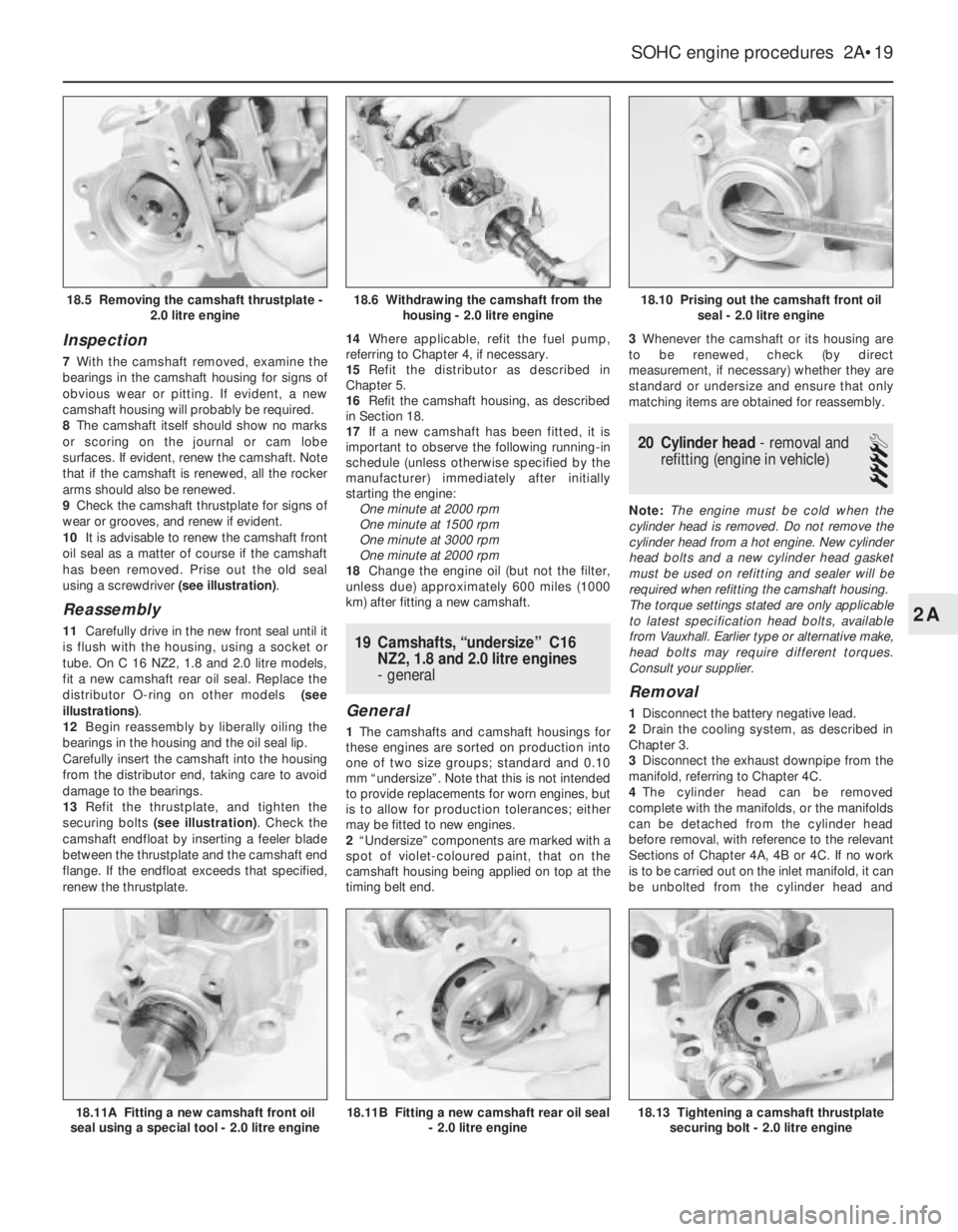
4Working at the distributor end of the
camshaft, unscrew the two camshaft
thrustplate securing bolts, using an Allen key
or hexagon bit (see illustration).
5Withdraw the thrustplate, noting which way
round it is fitted (see illustration).
6Carefully withdraw the camshaft from the
distributor end of the camshaft housing,
taking care not to damage the bearing
journals (see illustration).
2A•18SOHC engine procedures
14.8 Timing belt adjustment
1 Alignment for new belts
2 Alignment for ‘run-in’ belts (gap is
approximately 4 mm to the left of centre)
18.4 Camshaft thrustplate and
securing bolts -
1.6 litre engine
Page 216 of 525
Inspection
7With the camshaft removed, examine the
bearings in the camshaft housing for signs of
obvious wear or pitting. If evident, a new
camshaft housing will probably be required.
8The camshaft itself should show no marks
or scoring on the journal or cam lobe
surfaces. If evident, renew the camshaft. Note
that if the camshaft is renewed, all the rocker
arms should also be renewed.
9Check the camshaft thrustplate for signs of
wear or grooves, and renew if evident.
10It is advisable to renew the camshaft front
oil seal as a matter of course if the camshaft
has been removed. Prise out the old seal
using a screwdriver (see illustration).
Reassembly
11Carefully drive in the new front seal until it
is flush with the housing, using a socket or
tube. On C 16 NZ2, 1.8 and 2.0 litre models,
fit a new camshaft rear oil seal. Replace the
distributor O-ring on other models (see
illustrations).
12Begin reassembly by liberally oiling the
bearings in the housing and the oil seal lip.
Carefully insert the camshaft into the housing
from the distributor end, taking care to avoid
damage to the bearings.
13Refit the thrustplate, and tighten the
securing bolts (see illustration). Check the
camshaft endfloat by inserting a feeler blade
between the thrustplate and the camshaft end
flange. If the endfloat exceeds that specified,
renew the thrustplate.14Where applicable, refit the fuel pump,
referring to Chapter 4, if necessary.
15Refit the distributor as described in
Chapter 5.
16Refit the camshaft housing, as described
in Section 18.
17If a new camshaft has been fitted, it is
important to observe the following running-in
schedule (unless otherwise specified by the
manufacturer) immediately after initially
starting the engine:
One minute at 2000 rpm
One minute at 1500 rpm
One minute at 3000 rpm
One minute at 2000 rpm
18Change the engine oil (but not the filter,
unless due) approximately 600 miles (1000
km) after fitting a new camshaft.19Camshafts, “undersize” C16
NZ2, 1.8 and 2.0 litre engines
- general
General
1The camshafts and camshaft housings for
these engines are sorted on production into
one of two size groups; standard and 0.10
mm “undersize”. Note that this is not intended
to provide replacements for worn engines, but
is to allow for production tolerances; either
may be fitted to new engines.
2“Undersize” components are marked with a
spot of violet-coloured paint, that on the
camshaft housing being applied on top at the
timing belt end.3Whenever the camshaft or its housing are
to be renewed, check (by direct
measurement, if necessary) whether they are
standard or undersize and ensure that only
matching items are obtained for reassembly.
20Cylinder head - removal and
refitting (engine in vehicle)
4
Note: The engine must be cold when the
cylinder head is removed. Do not remove the
cylinder head from a hot engine. New cylinder
head bolts and a new cylinder head gasket
must be used on refitting and sealer will be
required when refitting the camshaft housing.
The torque settings stated are only applicable
to latest specification head bolts, available
from Vauxhall. Earlier type or alternative make,
head bolts may require different torques.
Consult your supplier.
Removal
1Disconnect the battery negative lead.
2Drain the cooling system, as described in
Chapter 3.
3Disconnect the exhaust downpipe from the
manifold, referring to Chapter 4C.
4The cylinder head can be removed
complete with the manifolds, or the manifolds
can be detached from the cylinder head
before removal, with reference to the relevant
Sections of Chapter 4A, 4B or 4C. If no work
is to be carried out on the inlet manifold, it can
be unbolted from the cylinder head and
SOHC engine procedures 2A•19
18.10 Prising out the camshaft front oil
seal - 2.0 litre engine
18.13 Tightening a camshaft thrustplate
securing bolt - 2.0 litre engine18.11B Fitting a new camshaft rear oil seal
- 2.0 litre engine18.11A Fitting a new camshaft front oil
seal using a special tool - 2.0 litre engine
18.6 Withdrawing the camshaft from the
housing - 2.0 litre engine18.5 Removing the camshaft thrustplate -
2.0 litre engine
2A
Page 217 of 525
supported to one side out of the way, thus
avoiding the need to disconnect the relevant
hoses, pipes and wiring.
5If the cylinder head is to be removed
complete with the manifolds, disconnect all
relevant hoses, pipes and wiring from the inlet
manifold and associated components,
referring to Chapter 4A or 4B. On carburettor
models, disconnect the hot air hose from the
shroud on the exhaust manifold. Loosen the
alternator mountings, with reference to
Chapter 5, then unbolt the upper alternator
mounting from the inlet manifold.
6If the inlet manifold is to be left in the engine
compartment, continue as follows, otherwise
go on to paragraph 15.
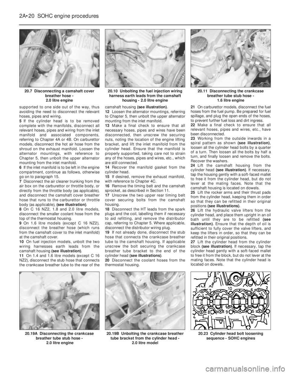
7Disconnect the air cleaner trunking from the
air box on the carburettor or throttle body, or
directly from the throttle body (as applicable),
and disconnect the camshaft cover breather
hose that runs to the carburettor or throttle
body (as applicable), (see illustration).
8On C 16 NZ2, 1.8 and 2.0 litre models,
disconnect the smaller coolant hose from the
top of the thermostat housing.
9On 1.6 litre models (except C 16 NZ2),
disconnect the breather hose (which runs
from the camshaft cover to the inlet manifold)
at the camshaft cover.
10On fuel injection models, unbolt the two
wiring harnesses earth leads from the
camshaft housing (see illustration).
11On 1.4 and 1.6 litre models (except C 16
NZ2), disconnect the stub hose that connects
the crankcase breather tube to the rear of thecamshaft housing (see illustration).
12Loosen the alternator mountings, referring
to Chapter 5, then unbolt the upper alternator
mounting from the inlet manifold.
13Make a final check to ensure that all
necessary hoses, pipes and wires have been
disconnected, then unscrew the securing
nuts, noting the location of the engine lifting
bracket, and lift the inlet manifold from the
cylinder head. Ensure that the manifold is
properly supported, taking care not to strain
any of the hoses, pipes and wires, etc., which
are still connected.
14Recover the manifold gasket from the
cylinder head.
15If desired, remove the exhaust manifold,
with reference to Chapter 4C.
16Remove the timing belt and the camshaft
sprocket, as described in Section 11.
17Unscrew the two upper rear timing belt
cover securing bolts from the camshaft
housing.
18Disconnect the HT leads from the spark
plugs and the coil, labelling them if necessary
to aid refitting, and remove the distributor
cap, referring to Chapter 5. Where applicable,
disconnect the distributor wiring plug.
19If not already done, disconnect the stub
hose that connects the crankcase breather
tube to the camshaft housing. If applicable
unscrew the bolt securing the crankcase
breather tube bracket to the end of the
cylinder head (see illustrations).
20Disconnect the coolant hoses from the
thermostat housing.21On carburettor models, disconnect the fuel
hoses from the fuel pump. Be prepared for fuel
spillage, and plug the open ends of the hoses,
to prevent further fuel loss and dirt ingress.
22Make a final check to ensure that all
relevant hoses, pipes and wires, etc., have
been disconnected.
23Working from the outside inwards in a
spiral pattern as shown (see illustration),
loosen all the cylinder head bolts by a quarter
of a turn. Then loosen all the bolts by half a
turn, and finally loosen and remove the bolts.
Recover the washers.
24Lift the camshaft housing from the
cylinder head (see illustration). If necessary,
tap the housing gently with a soft-faced mallet
to free it from the cylinder head, but do not
lever at the mating faces. Note that the
camshaft housing is located on dowels.
25Lift the rocker arms and their thrust pads
from the cylinder head, keeping them in order
so that they can be refitted in their original
positions (see illustrations).
26Lift the hydraulic valve lifters from the
cylinder head, and place them upright in an oil
bath until they are to be refitted (see
illustration). Ensure that the depth of oil is
sufficient to fully cover the valve lifters, and
keep the lifters in order, so that they can be
refitted in their original positions.
27Lift the cylinder head from the cylinder
block (see illustration). If necessary, tap the
cylinder head gently with a soft-faced mallet
to free it from the block, but do not lever at the
mating faces. Note that the cylinder head is
located on dowels.
2A•20SOHC engine procedures
20.7 Disconnecting a camshaft cover
breather hose -
2.0 litre engine20.11 Disconnecting the crankcase
breather tube stub hose -
1.6 litre engine
20.23 Cylinder head bolt loosening
sequence - SOHC engines20.19B Unbolting the crankcase breather
tube bracket from the cylinder head -
2.0 litre model20.19A Disconnecting the crankcase
breather tube stub hose -
2.0 litre engine
20.10 Unbolting the fuel injection wiring
harness earth leads from the camshaft
housing - 2.0 litre engine
Page 218 of 525
28Recover the cylinder head gasket and
discard it.
Refitting
29Clean the cylinder head and block mating
faces, and the camshaft housing and cylinder
head mating faces by careful scraping. Take
care not to damage the cylinder head and
camshaft housing, which are made of light
alloy and are easily scored. Cover the coolant
passages and other openings with masking
tape or rag to prevent dirt and carbon falling
in. Mop out all the oil from the bolt holes; if oil
is left in the holes, hydraulic pressure could
crack the block when the bolts are refitted.
30If desired, the cylinder head can be
dismantled and inspected as described in
Sections 22 and 23, and the camshaft
housing can be dismantled as described in
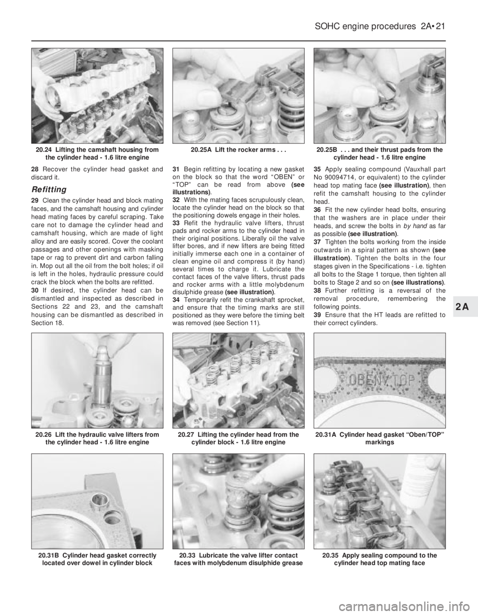
Section 18.31Begin refitting by locating a new gasket
on the block so that the word “OBEN” or
“TOP” can be read from above (see
illustrations).
32With the mating faces scrupulously clean,
locate the cylinder head on the block so that
the positioning dowels engage in their holes.
33Refit the hydraulic valve lifters, thrust
pads and rocker arms to the cylinder head in
their original positions. Liberally oil the valve
lifter bores, and if new lifters are being fitted
initially immerse each one in a container of
clean engine oil and compress it (by hand)
several times to charge it. Lubricate the
contact faces of the valve lifters, thrust pads
and rocker arms with a little molybdenum
disulphide grease (see illustration).
34Temporarily refit the crankshaft sprocket,
and ensure that the timing marks are still
positioned as they were before the timing belt
was removed (see Section 11).35Apply sealing compound (Vauxhall part
No 90094714, or equivalent) to the cylinder
head top mating face (see illustration), then
refit the camshaft housing to the cylinder
head.
36Fit the new cylinder head bolts, ensuring
that the washers are in place under their
heads, and screw the bolts in by hand as far
as possible (see illustration).
37Tighten the bolts working from the inside
outwards in a spiral pattern as shown (see
illustration). Tighten the bolts in the four
stages given in the Specifications -i.e. tighten
all bolts to the Stage 1 torque, then tighten all
bolts to Stage 2 and so on (see illustrations).
38Further refitting is a reversal of the
removal procedure, remembering the
following points.
39Ensure that the HT leads are refitted to
their correct cylinders.
SOHC engine procedures 2A•21
20.25B . . . and their thrust pads from the
cylinder head - 1.6 litre engine
20.35 Apply sealing compound to the
cylinder head top mating face20.33 Lubricate the valve lifter contact
faces with molybdenum disulphide grease20.31B Cylinder head gasket correctly
located over dowel in cylinder block
20.31A Cylinder head gasket “Oben/TOP”
markings20.27 Lifting the cylinder head from the
cylinder block - 1.6 litre engine20.26 Lift the hydraulic valve lifters from
the cylinder head - 1.6 litre engine
20.25A Lift the rocker arms . . .20.24 Lifting the camshaft housing from
the cylinder head - 1.6 litre engine
2A
Page 219 of 525
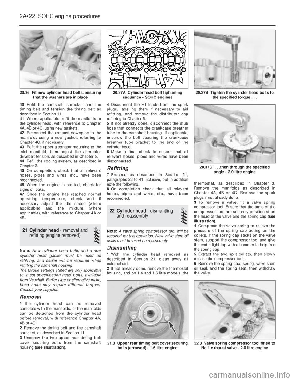
40Refit the camshaft sprocket and the
timing belt and tension the timing belt as
described in Section 11.
41Where applicable, refit the manifolds to
the cylinder head, with reference to Chapter
4A, 4B or 4C, using new gaskets.
42Reconnect the exhaust downpipe to the
manifold, using a new gasket, referring to
Chapter 4C, if necessary.
43Refit the upper alternator mounting to the
inlet manifold, then adjust the alternator
drivebelt tension, as described in Chapter 5.
44Refill the cooling system, as described in
Chapter 3.
45On completion, check that all relevant
hoses, pipes and wires, etc., have been
reconnected.
46When the engine is started, check for
signs of leaks.
47Once the engine has reached normal
operating temperature, check and if
necessary adjust the idle speed (where
applicable) and the mixture (where
applicable), with reference to Chapter 4A or
4B.
21Cylinder head - removal and
refitting (engine removed)
4
Note: New cylinder head bolts and a new
cylinder head gasket must be used on
refitting, and sealer will be required when
refitting the camshaft housing.
The torque settings stated are only applicable
to latest specification head bolts, available
from Vauxhall. Earlier type or alternative make,
head bolts may require different torques.
Consult your supplier.
Removal
1The cylinder head can be removed
complete with the manifolds, or the manifolds
can be detached from the cylinder head
before removal, with reference Chapter 4A,
4B or 4C.
2Remove the timing belt and the camshaft
sprocket, as described in Section 11.
3Unscrew the two upper rear timing belt
cover securing bolts from the camshaft
housing (see illustration).4Disconnect the HT leads from the spark
plugs, labelling them if necessary to aid
refitting, and remove the distributor cap
referring to Chapter 5.
5If not already done, disconnect the stub
hose that connects the crankcase breather
tube to the camshaft housing. If applicable,
unscrew the bolt securing the crankcase
breather tube bracket to the end of the
cylinder head.
6Make a final check to ensure that all
relevant hoses, pipes and wires have been
disconnected.
Refitting
7Proceed as described in Section 21,
paragraphs 23 to 41 inclusive, but in addition
note the following.
8On completion check that all relevant
hoses, pipes and wires, etc., have been
reconnected.
22Cylinder head -dismantling
and reassembly
4
Note: A valve spring compressor tool will be
required for this operation. New valve stem oil
seals must be used on reassembly
Dismantling
1With the cylinder head removed as
described in Section 21, clean away all
external dirt.
2If not already done, remove the thermostat
housing, and on 1.4 and 1.6 litre models, thethermostat, as described in Chapter 3.
Remove the manifolds as described in
Chapter 4A, 4B or 4C. Remove the spark
plugs if not already done.
3To remove a valve, fit a valve spring
compressor tool. Ensure that the arms of the
compressor tool are securely positioned on
the head of the valve and the spring cap (see
illustration).
4Compress the valve spring to relieve the
pressure of the spring cap acting on the
collets. If the spring cap sticks on the valve
stem, support the compressor tool and give
the end a light tap with a hammer to help free
the spring cap.
5Extract the two split collets, then slowly
release the compressor tool.
6Remove the spring cap, spring, valve stem
oil seal, and the spring seat, then withdraw
the valve.
2A•22SOHC engine procedures
20.36 Fit new cylinder head bolts, ensuring
that the washers are in place20.37B Tighten the cylinder head bolts to
the specified torque . . .
22.3 Valve spring compressor tool fitted to
No 1 exhaust valve - 2.0 litre engine21.3 Upper rear timing belt cover securing
bolts (arrowed) - 1.6 litre engine
20.37C . . .then through the specified
angle - 2.0 litre engine
20.37A Cylinder head bolt tightening
sequence - SOHC engines
Page 220 of 525
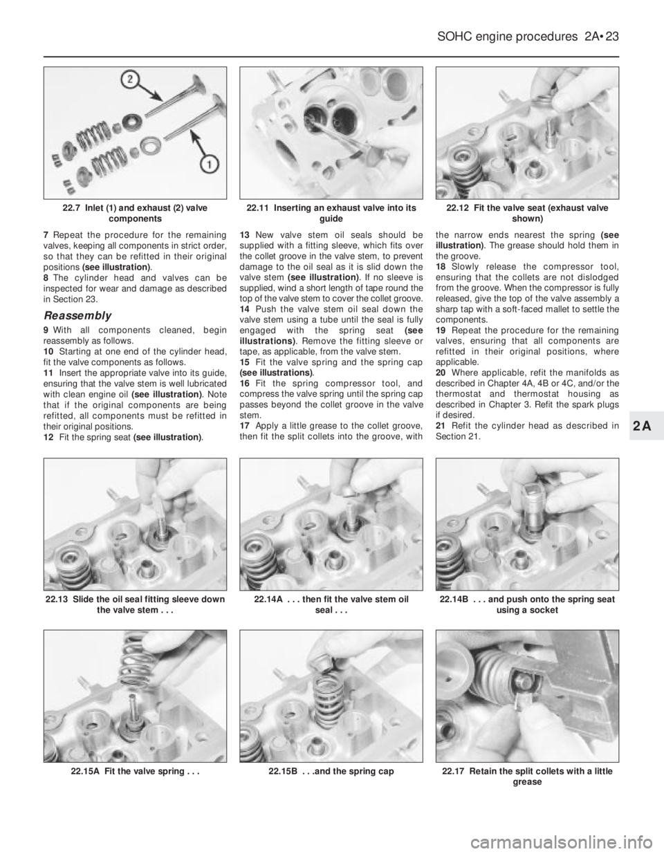
7Repeat the procedure for the remaining
valves, keeping all components in strict order,
so that they can be refitted in their original
positions (see illustration).
8The cylinder head and valves can be
inspected for wear and damage as described
in Section 23.
Reassembly
9With all components cleaned, begin
reassembly as follows.
10Starting at one end of the cylinder head,
fit the valve components as follows.
11Insert the appropriate valve into its guide,
ensuring that the valve stem is well lubricated
with clean engine oil (see illustration). Note
that if the original components are being
refitted, all components must be refitted in
their original positions.
12Fit the spring seat (see illustration).13New valve stem oil seals should be
supplied with a fitting sleeve, which fits over
the collet groove in the valve stem, to prevent
damage to the oil seal as it is slid down the
valve stem (see illustration). If no sleeve is
supplied, wind a short length of tape round the
top of the valve stem to cover the collet groove.
14Push the valve stem oil seal down the
valve stem using a tube until the seal is fully
engaged with the spring seat (see
illustrations). Remove the fitting sleeve or
tape, as applicable, from the valve stem.
15Fit the valve spring and the spring cap
(see illustrations).
16Fit the spring compressor tool, and
compress the valve spring until the spring cap
passes beyond the collet groove in the valve
stem.
17Apply a little grease to the collet groove,
then fit the split collets into the groove, withthe narrow ends nearest the spring (see
illustration). The grease should hold them in
the groove.
18Slowly release the compressor tool,
ensuring that the collets are not dislodged
from the groove. When the compressor is fully
released, give the top of the valve assembly a
sharp tap with a soft-faced mallet to settle the
components.
19Repeat the procedure for the remaining
valves, ensuring that all components are
refitted in their original positions, where
applicable.
20Where applicable, refit the manifolds as
described in Chapter 4A, 4B or 4C, and/or the
thermostat and thermostat housing as
described in Chapter 3. Refit the spark plugs
if desired.
21Refit the cylinder head as described in
Section 21.
SOHC engine procedures 2A•23
22.12 Fit the valve seat (exhaust valve
shown)
22.17 Retain the split collets with a little
grease22.15B . . .and the spring cap22.15A Fit the valve spring . . .
22.14B . . . and push onto the spring seat
using a socket22.14A . . . then fit the valve stem oil
seal . . .22.13 Slide the oil seal fitting sleeve down
the valve stem . . .
22.11 Inserting an exhaust valve into its
guide22.7 Inlet (1) and exhaust (2) valve
components
2A