OPEL VECTRA 1988 Service Repair Manual
Manufacturer: OPEL, Model Year: 1988, Model line: VECTRA, Model: OPEL VECTRA 1988Pages: 525, PDF Size: 58.26 MB
Page 231 of 525
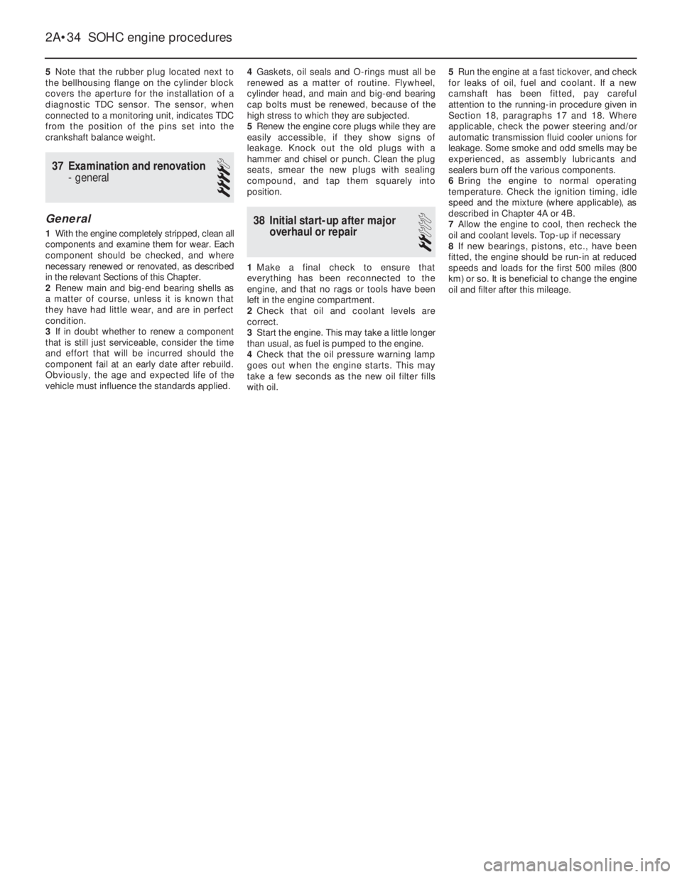
5Note that the rubber plug located next to
the bellhousing flange on the cylinder block
covers the aperture for the installation of a
diagnostic TDC sensor. The sensor, when
connected to a monitoring unit, indicates TDC
from the position of the pins set into the
crankshaft balance weight.
37Examination and renovation
-general
4
General
1With the engine completely stripped, clean all
components and examine them for wear. Each
component should be checked, and where
necessary renewed or renovated, as described
in the relevant Sections of this Chapter.
2Renew main and big-end bearing shells as
a matter of course, unless it is known that
they have had little wear, and are in perfect
condition.
3If in doubt whether to renew a component
that is still just serviceable, consider the time
and effort that will be incurred should the
component fail at an early date after rebuild.
Obviously, the age and expected life of the
vehicle must influence the standards applied.4Gaskets, oil seals and O-rings must all be
renewed as a matter of routine. Flywheel,
cylinder head, and main and big-end bearing
cap bolts must be renewed, because of the
high stress to which they are subjected.
5Renew the engine core plugs while they are
easily accessible, if they show signs of
leakage. Knock out the old plugs with a
hammer and chisel or punch. Clean the plug
seats, smear the new plugs with sealing
compound, and tap them squarely into
position.
38Initial start-up after major
overhaul or repair
2
1Make a final check to ensure that
everything has been reconnected to the
engine, and that no rags or tools have been
left in the engine compartment.
2Check that oil and coolant levels are
correct.
3Start the engine. This may take a little longer
than usual, as fuel is pumped to the engine.
4Check that the oil pressure warning lamp
goes out when the engine starts. This may
take a few seconds as the new oil filter fills
with oil.5Run the engine at a fast tickover, and check
for leaks of oil, fuel and coolant. If a new
camshaft has been fitted, pay careful
attention to the running-in procedure given in
Section 18, paragraphs 17 and 18. Where
applicable, check the power steering and/or
automatic transmission fluid cooler unions for
leakage. Some smoke and odd smells may be
experienced, as assembly lubricants and
sealers burn off the various components.
6Bring the engine to normal operating
temperature. Check the ignition timing, idle
speed and the mixture (where applicable), as
described in Chapter 4A or 4B.
7Allow the engine to cool, then recheck the
oil and coolant levels. Top-up if necessary
8If new bearings, pistons, etc., have been
fitted, the engine should be run-in at reduced
speeds and loads for the first 500 miles (800
km) or so. It is beneficial to change the engine
oil and filter after this mileage.
2A•34SOHC engine procedures
Page 232 of 525
3
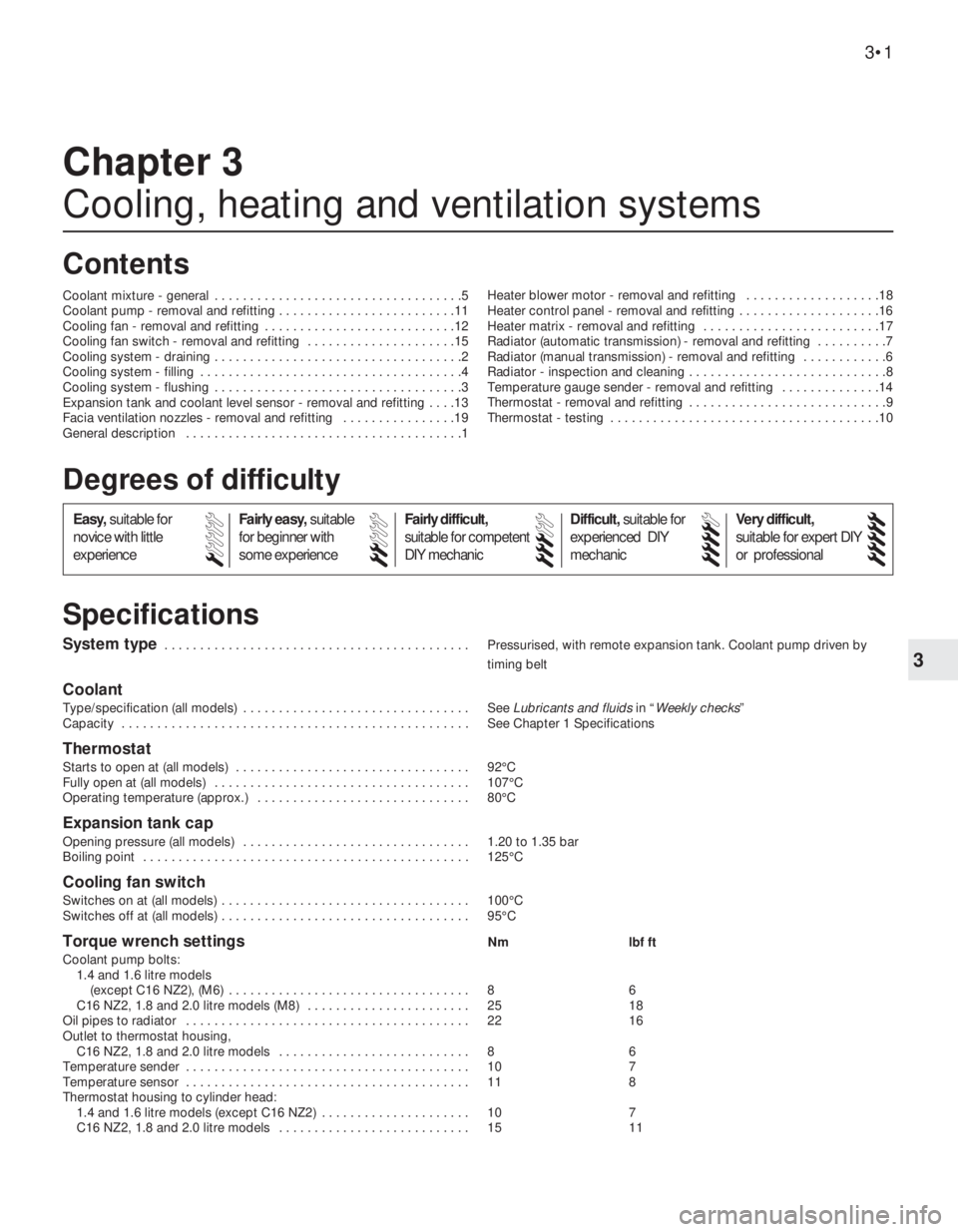
System type . . . . . . . . . . . . . . . . . . . . . . . . . . . . . . . . . . . . . . . . . . . Pressurised, with remote expansion tank. Coolant pump driven by
timing belt
Coolant
Type/specification (all models) . . . . . . . . . . . . . . . . . . . . . . . . . . . . . . . . See Lubricants and fluidsin “Weekly checks”
Capacity . . . . . . . . . . . . . . . . . . . . . . . . . . . . . . . . . . . . . . . . . . . . . . . . . See Chapter 1 Specifications
Thermostat
Starts to open at (all models) . . . . . . . . . . . . . . . . . . . . . . . . . . . . . . . . . 92°C
Fully open at (all models) . . . . . . . . . . . . . . . . . . . . . . . . . . . . . . . . . . . . 107°C
Operating temperature (approx.) . . . . . . . . . . . . . . . . . . . . . . . . . . . . . . 80°C
Expansion tank cap
Opening pressure (all models) . . . . . . . . . . . . . . . . . . . . . . . . . . . . . . . . 1.20 to 1.35 bar
Boiling point . . . . . . . . . . . . . . . . . . . . . . . . . . . . . . . . . . . . . . . . . . . . . . 125°C
Cooling fan switch
Switches on at (all models) . . . . . . . . . . . . . . . . . . . . . . . . . . . . . . . . . . . 100°C
Switches off at (all models) . . . . . . . . . . . . . . . . . . . . . . . . . . . . . . . . . . . 95°C
Torque wrench settingsNm lbf ft
Coolant pump bolts:
1.4 and 1.6 litre models
(except C16 NZ2), (M6) . . . . . . . . . . . . . . . . . . . . . . . . . . . . . . . . . . 8 6
C16 NZ2, 1.8 and 2.0 litre models (M8) . . . . . . . . . . . . . . . . . . . . . . . 25 18
Oil pipes to radiator . . . . . . . . . . . . . . . . . . . . . . . . . . . . . . . . . . . . . . . . 22 16
Outlet to thermostat housing,
C16 NZ2, 1.8 and 2.0 litre models . . . . . . . . . . . . . . . . . . . . . . . . . . . 8 6
Temperature sender . . . . . . . . . . . . . . . . . . . . . . . . . . . . . . . . . . . . . . . . 10 7
Temperature sensor . . . . . . . . . . . . . . . . . . . . . . . . . . . . . . . . . . . . . . . . 11 8
Thermostat housing to cylinder head:
1.4 and 1.6 litre models (except C16 NZ2) . . . . . . . . . . . . . . . . . . . . . 10 7
C16 NZ2, 1.8 and 2.0 litre models . . . . . . . . . . . . . . . . . . . . . . . . . . . 15 11
Chapter 3
Cooling, heating and ventilation systems
Coolant mixture - general . . . . . . . . . . . . . . . . . . . . . . . . . . . . . . . . . . .5
Coolant pump - removal and refitting . . . . . . . . . . . . . . . . . . . . . . . . .11
Cooling fan - removal and refitting . . . . . . . . . . . . . . . . . . . . . . . . . . .12
Cooling fan switch - removal and refitting . . . . . . . . . . . . . . . . . . . . .15
Cooling system - draining . . . . . . . . . . . . . . . . . . . . . . . . . . . . . . . . . . .2
Cooling system - filling . . . . . . . . . . . . . . . . . . . . . . . . . . . . . . . . . . . . .4
Cooling system - flushing . . . . . . . . . . . . . . . . . . . . . . . . . . . . . . . . . . .3
Expansion tank and coolant level sensor - removal and refitting . . . .13
Facia ventilation nozzles - removal and refitting . . . . . . . . . . . . . . . .19
General description . . . . . . . . . . . . . . . . . . . . . . . . . . . . . . . . . . . . . . .1Heater blower motor - removal and refitting . . . . . . . . . . . . . . . . . . .18
Heater control panel - removal and refitting . . . . . . . . . . . . . . . . . . . .16
Heater matrix - removal and refitting . . . . . . . . . . . . . . . . . . . . . . . . .17
Radiator (automatic transmission) - removal and refitting . . . . . . . . . .7
Radiator (manual transmission) - removal and refitting . . . . . . . . . . . .6
Radiator - inspection and cleaning . . . . . . . . . . . . . . . . . . . . . . . . . . . .8
Temperature gauge sender - removal and refitting . . . . . . . . . . . . . .14
Thermostat - removal and refitting . . . . . . . . . . . . . . . . . . . . . . . . . . . .9
Thermostat - testing . . . . . . . . . . . . . . . . . . . . . . . . . . . . . . . . . . . . . .10
3•1
Specifications Contents
Easy,suitable for
novice with little
experienceFairly easy,suitable
for beginner with
some experienceFairly difficult,
suitable for competent
DIY mechanic
Difficult,suitable for
experienced DIY
mechanicVery difficult,
suitable for expert DIY
or professional
Degrees of difficulty
54321
Page 233 of 525
1General description
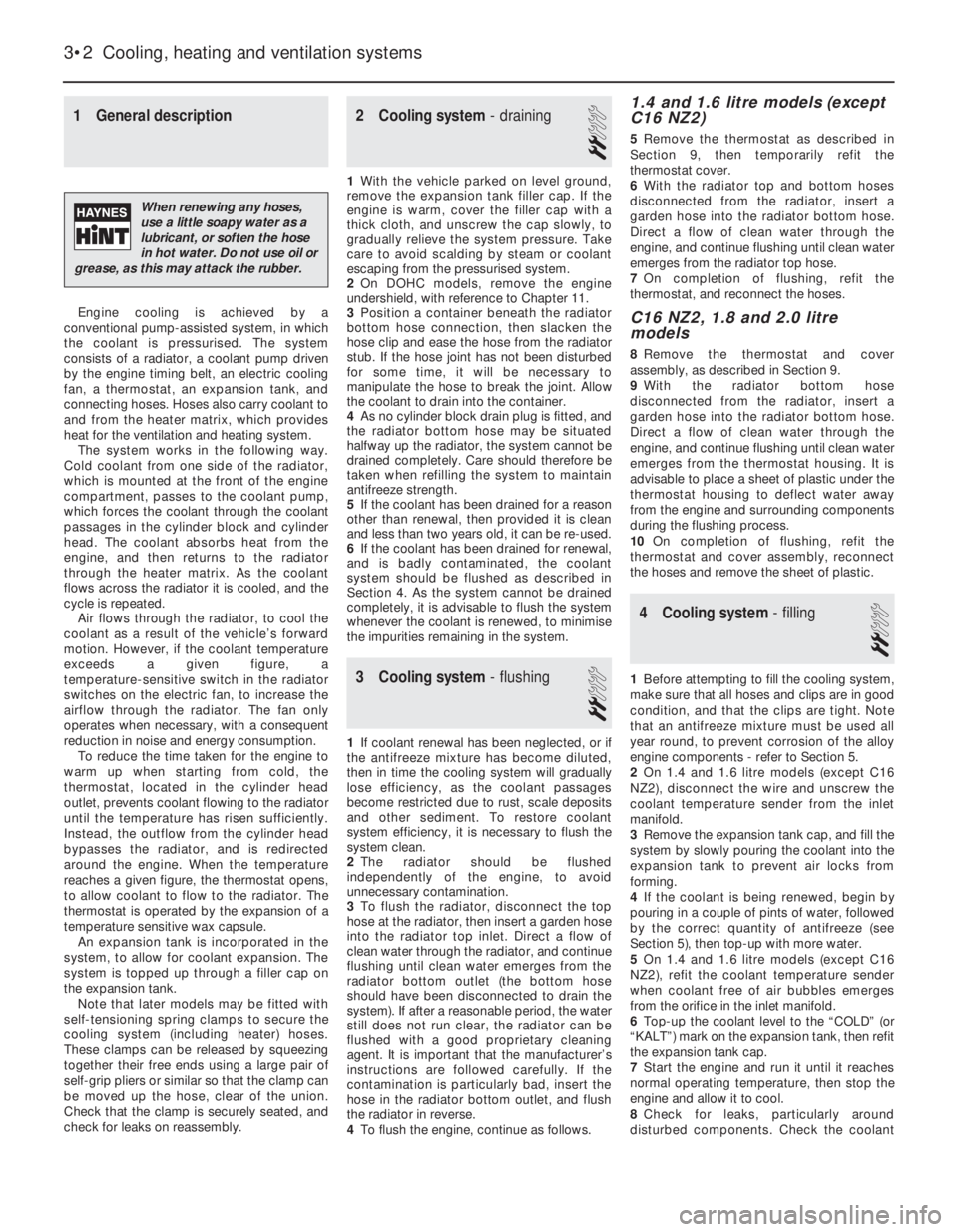
Engine cooling is achieved by a
conventional pump-assisted system, in which
the coolant is pressurised. The system
consists of a radiator, a coolant pump driven
by the engine timing belt, an electric cooling
fan, a thermostat, an expansion tank, and
connecting hoses. Hoses also carry coolant to
and from the heater matrix, which provides
heat for the ventilation and heating system.
The system works in the following way.
Cold coolant from one side of the radiator,
which is mounted at the front of the engine
compartment, passes to the coolant pump,
which forces the coolant through the coolant
passages in the cylinder block and cylinder
head. The coolant absorbs heat from the
engine, and then returns to the radiator
through the heater matrix. As the coolant
flows across the radiator it is cooled, and the
cycle is repeated.
Air flows through the radiator, to cool the
coolant as a result of the vehicle’s forward
motion. However, if the coolant temperature
exceeds a given figure, a
temperature-sensitive switch in the radiator
switches on the electric fan, to increase the
airflow through the radiator. The fan only
operates when necessary, with a consequent
reduction in noise and energy consumption.
To reduce the time taken for the engine to
warm up when starting from cold, the
thermostat, located in the cylinder head
outlet, prevents coolant flowing to the radiator
until the temperature has risen sufficiently.
Instead, the outflow from the cylinder head
bypasses the radiator, and is redirected
around the engine. When the temperature
reaches a given figure, the thermostat opens,
to allow coolant to flow to the radiator. The
thermostat is operated by the expansion of a
temperature sensitive wax capsule.
An expansion tank is incorporated in the
system, to allow for coolant expansion. The
system is topped up through a filler cap on
the expansion tank.
Note that later models may be fitted with
self-tensioning spring clamps to secure the
cooling system (including heater) hoses.
These clamps can be released by squeezing
together their free ends using a large pair of
self-grip pliers or similar so that the clamp can
be moved up the hose, clear of the union.
Check that the clamp is securely seated, and
check for leaks on reassembly.
2Cooling system -draining
2
1With the vehicle parked on level ground,
remove the expansion tank filler cap. If the
engine is warm, cover the filler cap with a
thick cloth, and unscrew the cap slowly, to
gradually relieve the system pressure. Take
care to avoid scalding by steam or coolant
escaping from the pressurised system.
2On DOHC models, remove the engine
undershield, with reference to Chapter 11.
3Position a container beneath the radiator
bottom hose connection, then slacken the
hose clip and ease the hose from the radiator
stub. If the hose joint has not been disturbed
for some time, it will be necessary to
manipulate the hose to break the joint. Allow
the coolant to drain into the container.
4As no cylinder block drain plug is fitted, and
the radiator bottom hose may be situated
halfway up the radiator, the system cannot be
drained completely. Care should therefore be
taken when refilling the system to maintain
antifreeze strength.
5If the coolant has been drained for a reason
other than renewal, then provided it is clean
and less than two years old, it can be re-used.
6If the coolant has been drained for renewal,
and is badly contaminated, the coolant
system should be flushed as described in
Section 4. As the system cannot be drained
completely, it is advisable to flush the system
whenever the coolant is renewed, to minimise
the impurities remaining in the system.
3Cooling system -flushing
2
1If coolant renewal has been neglected, or if
the antifreeze mixture has become diluted,
then in time the cooling system will gradually
lose efficiency, as the coolant passages
become restricted due to rust, scale deposits
and other sediment. To restore coolant
system efficiency, it is necessary to flush the
system clean.
2The radiator should be flushed
independently of the engine, to avoid
unnecessary contamination.
3To flush the radiator, disconnect the top
hose at the radiator, then insert a garden hose
into the radiator top inlet. Direct a flow of
clean water through the radiator, and continue
flushing until clean water emerges from the
radiator bottom outlet (the bottom hose
should have been disconnected to drain the
system). If after a reasonable period, the water
still does not run clear, the radiator can be
flushed with a good proprietary cleaning
agent. It is important that the manufacturer’s
instructions are followed carefully. If the
contamination is particularly bad, insert the
hose in the radiator bottom outlet, and flush
the radiator in reverse.
4To flush the engine, continue as follows.
1.4 and 1.6 litre models (except
C16 NZ2)
5Remove the thermostat as described in
Section 9, then temporarily refit the
thermostat cover.
6With the radiator top and bottom hoses
disconnected from the radiator, insert a
garden hose into the radiator bottom hose.
Direct a flow of clean water through the
engine, and continue flushing until clean water
emerges from the radiator top hose.
7On completion of flushing, refit the
thermostat, and reconnect the hoses.
C16 NZ2, 1.8 and 2.0 litre
models
8Remove the thermostat and cover
assembly, as described in Section 9.
9With the radiator bottom hose
disconnected from the radiator, insert a
garden hose into the radiator bottom hose.
Direct a flow of clean water through the
engine, and continue flushing until clean water
emerges from the thermostat housing. It is
advisable to place a sheet of plastic under the
thermostat housing to deflect water away
from the engine and surrounding components
during the flushing process.
10On completion of flushing, refit the
thermostat and cover assembly, reconnect
the hoses and remove the sheet of plastic.
4Cooling system -filling
2
1Before attempting to fill the cooling system,
make sure that all hoses and clips are in good
condition, and that the clips are tight. Note
that an antifreeze mixture must be used all
year round, to prevent corrosion of the alloy
engine components -refer to Section 5.
2On 1.4 and 1.6 litre models (except C16
NZ2), disconnect the wire and unscrew the
coolant temperature sender from the inlet
manifold.
3Remove the expansion tank cap, and fill the
system by slowly pouring the coolant into the
expansion tank to prevent air locks from
forming.
4If the coolant is being renewed, begin by
pouring in a couple of pints of water, followed
by the correct quantity of antifreeze (see
Section 5), then top-up with more water.
5On 1.4 and 1.6 litre models (except C16
NZ2), refit the coolant temperature sender
when coolant free of air bubbles emerges
from the orifice in the inlet manifold.
6Top-up the coolant level to the “COLD” (or
“KALT”) mark on the expansion tank, then refit
the expansion tank cap.
7Start the engine and run it until it reaches
normal operating temperature, then stop the
engine and allow it to cool.
8Check for leaks, particularly around
disturbed components. Check the coolant
3•2Cooling, heating and ventilation systems
When renewing any hoses,
use a little soapy water as a
lubricant, or soften the hose
in hot water. Do not use oil or
grease, as this may attack the rubber.
Page 234 of 525
level in the expansion tank, and top-up if
necessary. Note that the system must be cold
before an accurate level is indicated in the
expansion tank. If the expansion tank cap is
removed while the engine is still warm, cover
the cap with a thick cloth and unscrew the
cap slowly, to gradually relieve the system
pressure. Take care to avoid scalding by
steam or coolant escaping from the
pressurised system.
9On DOHC models, refit the engine
undershield on completion.
5Coolant mixture -general
1It is important to use an antifreeze mixture
in the cooling system all year round, to
prevent corrosion of the alloy engine
components. The coolant mixture should be
made up from clean, preferably soft, tap
water, and a good quality antifreeze
containing corrosion inhibitor. Ensure that the
antifreeze is ethylene glycol based, as the
cheaper methanol based types evaporate
over a period of time.
2The proportions of water and antifreeze
used will depend on the degree of protection
required. A coolant mixture containing 25%
antifreeze should be regarded as the
minimum strength required to maintain good
anti-corrosion properties. Details of the
degree of protection provided against freezing
will be supplied with the antifreeze by the
manufacturers. For absolute protection, use a
50% antifreeze mixture.
3The coolant mixture should be renewed
every two years, as the corrosion inhibitors
will deteriorate with time.
4Before filling the system with fresh coolant,
drain and flush the system, as described in
Sections 2 and 3, and check that all hoses are
secure and that the clips are tight. Antifreeze
has a searching action, and will leak morerapidly than plain water.
5Refill the system as described in Section 4.
All future topping-up should be carried out
using a coolant mixture of the same
proportions as that used to initially fill the
system.
6Do not use antifreeze in the windscreen
wash system, as it will attack the vehicle
paintwork. Note that antifreeze is poisonous,
and must be handled with due care.
6Radiator (manual
transmission) -removal and
refitting
3
Removal
1The radiator can be removed complete with
the coolant fan and shroud if there is no need
to disturb the fan. If desired, the fan and its
shroud can be removed from the radiator,
with reference to Section 12.
2Drain the cooling system, as described in
Section 2.
3Disconnect the radiator top hose and the
expansion tank at the radiator.
4Disconnect the battery negative lead, then
disconnect the wiring from the cooling fan
switch, located at the bottom right-hand side
of the radiator.5Disconnect the cooling fan wiring
connector, noting its location for use when
refitting.
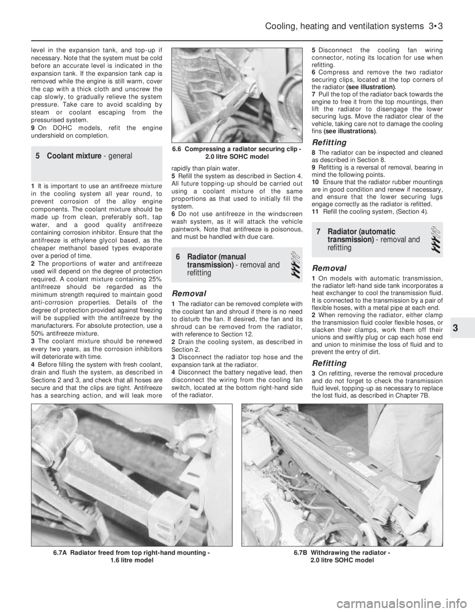
6Compress and remove the two radiator
securing clips, located at the top corners of
the radiator (see illustration).
7Pull the top of the radiator back towards the
engine to free it from the top mountings, then
lift the radiator to disengage the lower
securing lugs. Move the radiator clear of the
vehicle, taking care not to damage the cooling
fins (see illustrations).
Refitting
8The radiator can be inspected and cleaned
as described in Section 8.
9Refitting is a reversal of removal, bearing in
mind the following points.
10Ensure that the radiator rubber mountings
are in good condition and renew if necessary,
and ensure that the lower securing lugs
engage correctly as the radiator is refitted.
11Refill the cooling system, (Section 4).
7Radiator (automatic
transmission) -removal and
refitting
3
Removal
1On models with automatic transmission,
the radiator left-hand side tank incorporates a
heat exchanger to cool the transmission fluid.
It is connected to the transmission by a pair of
flexible hoses, with a metal pipe at each end.
2When removing the radiator, either clamp
the transmission fluid cooler flexible hoses, or
slacken their clamps, work them off their
unions and swiftly plug or cap each hose end
and union to minimise the loss of fluid and to
prevent the entry of dirt.
Refitting
3On refitting, reverse the removal procedure
and do not forget to check the transmission
fluid level, topping-up as necessary to replace
the lost fluid, as described in Chapter 7B.
Cooling, heating and ventilation systems 3•3
6.7B Withdrawing the radiator -
2.0 litre SOHC model6.7A Radiator freed from top right-hand mounting -
1.6 litre model
6.6 Compressing a radiator securing clip -
2.0 litre SOHC model
3
Page 235 of 525
8Radiator -inspection and
cleaning
2
1If the radiator has been removed due to
suspected blockage, reverse-flush it as
described in Section 3.
2Clean dirt and debris from the radiator fins,
using an air jet or a soft brush. Take care, as
the fins are easily damaged and are sharp.
3If necessary, a radiator specialist can
perform a “flow test” on the radiator, to
establish whether an internal blockage exists.
4A leaking radiator must be referred to a
specialist for permanent repair. Do not
attempt to weld or solder a leaking radiator,
as damage to the plastic components may
result.
5In an emergency, minor leaks from the
radiator can be cured by using a radiator
sealant.
9Thermostat - removal and
refitting
3
Note: A new O-ring should be used when
refitting the thermostat
1.4 and 1.6 litre models (except
C16 NZ2)
Removal
1Partially drain the cooling system, as
described in Section 2.
2Remove the timing belt and the camshaft
sprocket, as described in Chapters 2A or 2B,
(as applicable).
3Unscrew and remove the two upper bolts
securing the rear timing belt cover to the
cylinder head, and the lower right-hand bolt
securing the cover to the cylinder block.
4Disconnect the coolant hose from the
thermostat housing.
5Pull the rear timing belt cover forwards,
away from the cylinder head, for access to the
two thermostat housing securing bolts.
6Unscrew and remove the two thermostat
housing securing bolts, and lift off the
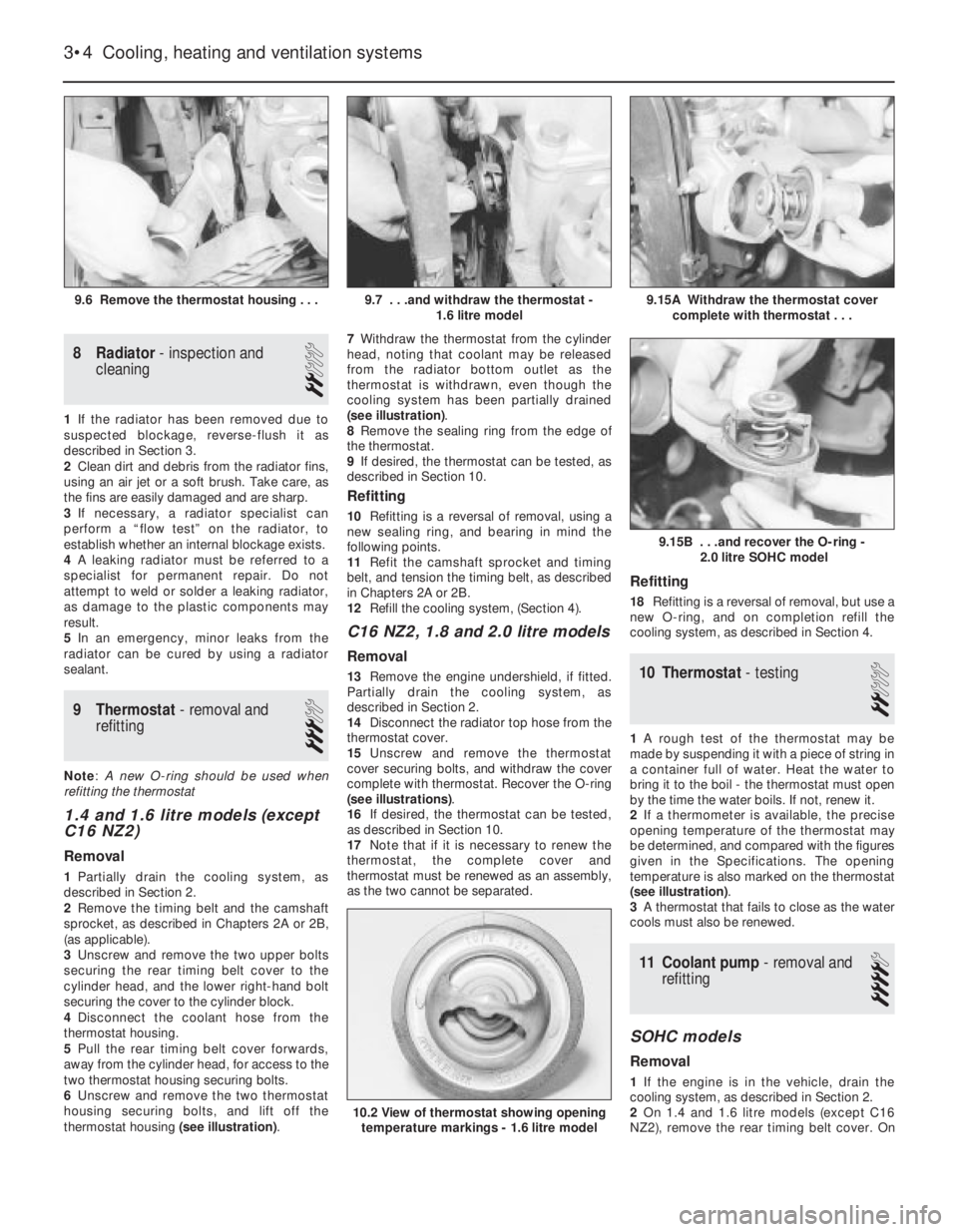
thermostat housing (see illustration).7Withdraw the thermostat from the cylinder
head, noting that coolant may be released
from the radiator bottom outlet as the
thermostat is withdrawn, even though the
cooling system has been partially drained
(see illustration).
8Remove the sealing ring from the edge of
the thermostat.
9If desired, the thermostat can be tested, as
described in Section 10.
Refitting
10Refitting is a reversal of removal, using a
new sealing ring, and bearing in mind the
following points.
11Refit the camshaft sprocket and timing
belt, and tension the timing belt, as described
in Chapters 2A or 2B.
12Refill the cooling system, (Section 4).
C16 NZ2, 1.8 and 2.0 litre models
Removal
13Remove the engine undershield, if fitted.
Partially drain the cooling system, as
described in Section 2.
14Disconnect the radiator top hose from the
thermostat cover.
15Unscrew and remove the thermostat
cover securing bolts, and withdraw the cover
complete with thermostat. Recover the O-ring
(see illustrations).
16If desired, the thermostat can be tested,
as described in Section 10.
17Note that if it is necessary to renew the
thermostat, the complete cover and
thermostat must be renewed as an assembly,
as the two cannot be separated.
Refitting
18Refitting is a reversal of removal, but use a
new O-ring, and on completion refill the
cooling system, as described in Section 4.
10Thermostat -testing
2
1A rough test of the thermostat may be
made by suspending it with a piece of string in
a container full of water. Heat the water to
bring it to the boil -the thermostat must open
by the time the water boils. If not, renew it.
2If a thermometer is available, the precise
opening temperature of the thermostat may
be determined, and compared with the figures
given in the Specifications. The opening
temperature is also marked on the thermostat
(see illustration).
3A thermostat that fails to close as the water
cools must also be renewed.
11Coolant pump -removal and
refitting
4
SOHC models
Removal
1If the engine is in the vehicle, drain the
cooling system, as described in Section 2.
2On 1.4 and 1.6 litre models (except C16
NZ2), remove the rear timing belt cover. On
3•4Cooling, heating and ventilation systems
9.6 Remove the thermostat housing . . .9.15A Withdraw the thermostat cover
complete with thermostat . . .
10.2 View of thermostat showing opening
temperature markings - 1.6 litre model
9.15B . . .and recover the O-ring -
2.0 litre SOHC model
9.7 . . .and withdraw the thermostat -
1.6 litre model
Page 236 of 525
C16 NZ2, 1.8 and 2.0 litre models, remove the
timing belt. Details are as described in
Chapter 2A.
3Remove timing belt tension roller from oil
pump, where applicable.
4Unscrew and remove the coolant pump
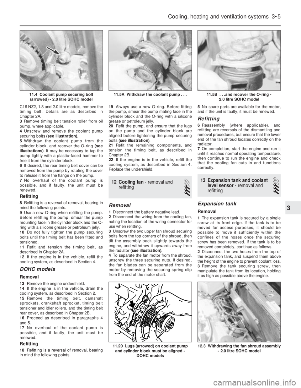
securing bolts (see illustration).
5Withdraw the coolant pump from the
cylinder block, and recover the O-ring (see
illustrations). It may be necessary to tap the
pump lightly with a plastic-faced hammer to
free it from the cylinder block.
6If desired, the rear timing belt cover can be
removed from the pump by rotating the cover
to release it from the flange on the pump.
7No overhaul of the coolant pump is
possible, and if faulty, the unit must be
renewed.
Refitting
8Refitting is a reversal of removal, bearing in
mind the following points.
9Use a new O-ring when refitting the pump.
Before refitting the pump, smear the pump
mounting face in the cylinder block and the O-
ring with a silicone grease or petroleum jelly.
10Do not fully tighten the pump securing
bolts until the timing belt has been fitted and
tensioned.
11Refit and tension the timing belt, as
described in Chapter 2A.
12If the engine is in the vehicle, refill the
cooling system, as described in Section 4.
DOHC models
Removal
13Remove the engine undershield.
14If the engine is in the vehicle, drain the
cooling system, as described in Section 2.
15Remove the timing belt, camshaft
sprockets, crankshaft sprocket, timing belt
tensioner and idler rollers, and the timing belt
rear cover, as described in Chapter 2B.
16Proceed as described in paragraphs 4
and 5.
17No overhaul of the coolant pump is
possible, and if faulty, the unit must be
renewed.
Refitting
18Refitting is a reversal of removal, bearing
in mind the following points.19Always use a new O-ring. Before fitting
the pump, smear the pump mating face in the
cylinder block and the O-ring with a silicone
grease or petroleum jelly.
20Refit the pump, and ensure that the lugs
on the pump and the cylinder block are
aligned before tightening the pump securing
bolts (see illustration).
21Refit the remaining components, and
tension the timing belt, as described in
Chapter 2B.
22If the engine is in the vehicle, refill the
cooling system, as described in Section 4.
Replace the undershield.
12Cooling fan - removal and
refitting
3
Removal
1Disconnect the battery negative lead.
2Disconnect the wiring from the cooling fan,
noting the location of the wiring connector for
use when refitting.
3Unscrew the two upper fan shroud securing
bolts from the top corners of the shroud, then
tilt the assembly back slightly towards the
engine, and withdraw it upwards away from
the radiator (see illustration).
4To separate the fan motor from the shroud,
unscrew the three securing nuts. If desired,
the fan blades can be separated from the
motor by removing the securing spring clip
from the end of the motor shaft.5No spare parts are available for the motor,
and if the unit is faulty, it must be renewed.
Refitting
6Reassembly (where applicable), and
refitting are reversals of the dismantling and
removal procedures, but ensure that the lower
end of the fan shroud locates correctly on the
radiator.
7On completion, start the engine and run it
until it reaches normal operating temperature,
then continue to run the engine and check
that the cooling fan cuts in and functions
correctly.
13Expansion tank and coolant
level sensor -removal and
refitting
3
Expansion tank
Removal
1The expansion tank is secured by a single
screw at its front edge. If the tank is to be
moved for access purposes, it should be
possible to move it sufficiently within the
confines of the hoses once the securing
screw has been removed. If the tank is to be
removed completely, continue as follows.
2Disconnect the two hoses from the top of
the expansion tank, and suspend them above
the height of the engine to prevent coolant loss.
3Remove the tank securing screw, then
manipulate the tank from its location, holding
it as high as possible above the engine.
Cooling, heating and ventilation systems 3•5
11.5B . . .and recover the O-ring -
2.0 litre SOHC model
12.3 Withdrawing the fan shroud assembly
- 2.0 litre SOHC model11.20 Lugs (arrowed) on coolant pump
and cylinder block must be aligned -
DOHC models
11.5A Withdraw the coolant pump . . .11.4 Coolant pump securing bolt
(arrowed) - 2.0 litre SOHC model
3
Page 237 of 525
4Position a container beneath the tank, then
disconnect the bottom hose and allow the
contents of the tank to drain into the
container. Suspend the bottom hose as high
as possible above the engine to prevent
coolant loss.
Refitting
5Refitting is a reversal of removal, but on
completion check and if necessary top-up the
coolant level, as described in Section 4. The
coolant drained from the expansion tank
during removal can be re-used, provided it
has not been contaminated.
Coolant level sensor
6The coolant level sensor, where fitted, is an
integral part of the expansion tank cap. If the
level sensor is faulty, the complete cap
assembly must be renewed.
14Temperature gauge sender -
removal and refitting
2
Removal
1The sender is screwed into the inlet
manifold on 1.4 and 1.6 litre models (except
C16 NZ2), and into the thermostat housing
on C16 NZ2, 1.8 and 2.0 litre models (see
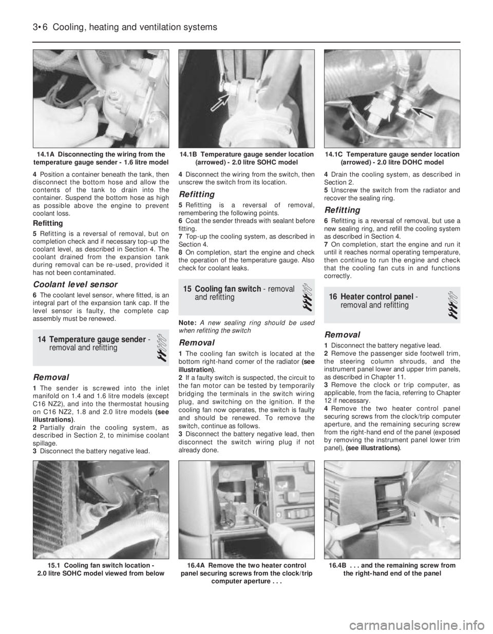
illustrations).
2Partially drain the cooling system, as
described in Section 2, to minimise coolant
spillage.
3Disconnect the battery negative lead.4Disconnect the wiring from the switch, then
unscrew the switch from its location.
Refitting
5Refitting is a reversal of removal,
remembering the following points.
6Coat the sender threads with sealant before
fitting.
7Top-up the cooling system, as described in
Section 4.
8On completion, start the engine and check
the operation of the temperature gauge. Also
check for coolant leaks.
15Cooling fan switch -removal
and refitting
3
Note: A new sealing ring should be used
when refitting the switch
Removal
1The cooling fan switch is located at the
bottom right-hand corner of the radiator (see
illustration).
2If a faulty switch is suspected, the circuit to
the fan motor can be tested by temporarily
bridging the terminals in the switch wiring
plug, and switching on the ignition. If the
cooling fan now operates, the switch is faulty
and should be renewed. To remove the
switch, continue as follows.
3Disconnect the battery negative lead, then
disconnect the switch wiring plug if not
already done.4Drain the cooling system, as described in
Section 2.
5Unscrew the switch from the radiator and
recover the sealing ring.
Refitting
6Refitting is a reversal of removal, but use a
new sealing ring, and refill the cooling system
as described in Section 4.
7On completion, start the engine and run it
until it reaches normal operating temperature,
then continue to run the engine and check
that the cooling fan cuts in and functions
correctly.
16Heater control panel -
removal and refitting
3
Removal
1Disconnect the battery negative lead.
2Remove the passenger side footwell trim,
the steering column shrouds, and the
instrument panel lower and upper trim panels,
as described in Chapter 11.
3Remove the clock or trip computer, as
applicable, from the facia, referring to Chapter
12 if necessary.
4Remove the two heater control panel
securing screws from the clock/trip computer
aperture, and the remaining securing screw
from the right-hand end of the panel (exposed
by removing the instrument panel lower trim
panel), (see illustrations).
3•6Cooling, heating and ventilation systems
14.1A Disconnecting the wiring from the
temperature gauge sender - 1.6 litre model14.1C Temperature gauge sender location
(arrowed) - 2.0 litre DOHC model
16.4B . . . and the remaining screw from
the right-hand end of the panel16.4A Remove the two heater control
panel securing screws from the clock/trip
computer aperture . . .15.1 Cooling fan switch location -
2.0 litre SOHC model viewed from below
14.1B Temperature gauge sender location
(arrowed) - 2.0 litre SOHC model
Page 238 of 525
5Working through the passenger footwell,
reach up behind the facia, and disconnect the
bowden cables from the control levers at the
rear of the heater control panel. Note that
each cable is secured by a plastic clip, and in
some cases, by an additional metal clip,
which must be released before the cable end
can be disconnected from the control lever
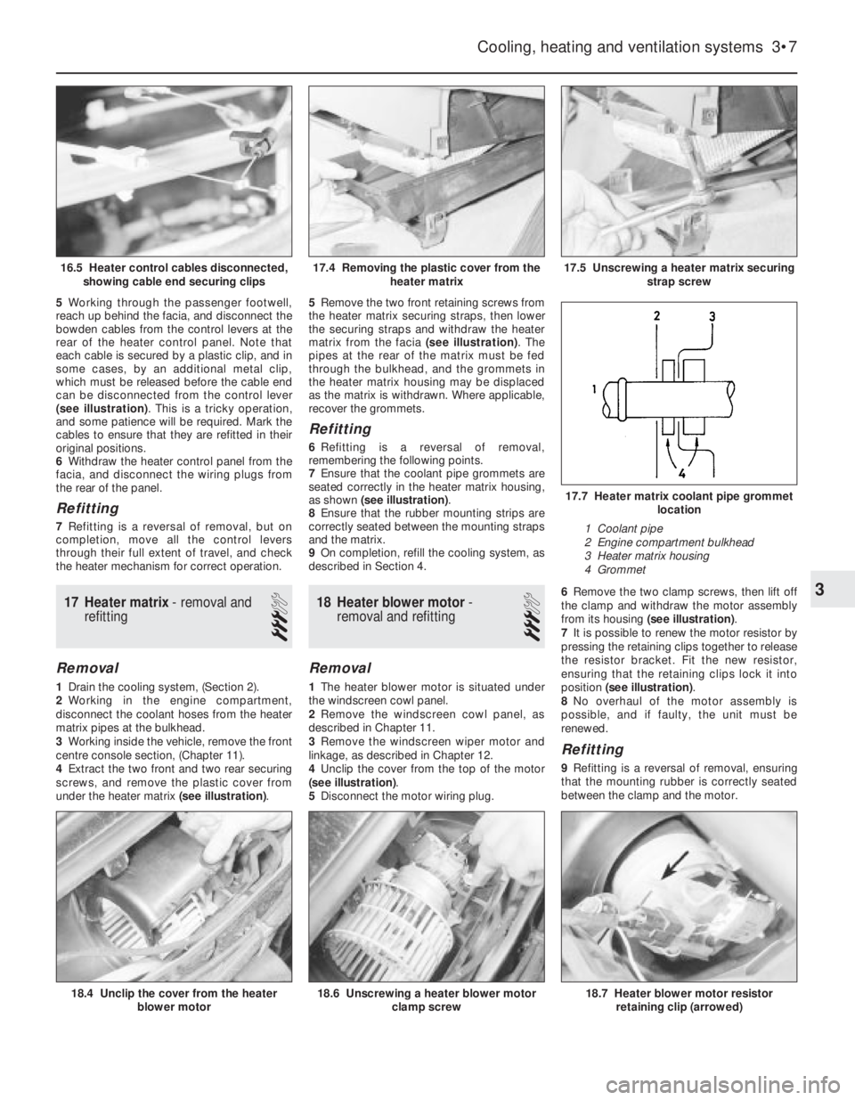
(see illustration). This is a tricky operation,
and some patience will be required. Mark the
cables to ensure that they are refitted in their
original positions.
6Withdraw the heater control panel from the
facia, and disconnect the wiring plugs from
the rear of the panel.
Refitting
7Refitting is a reversal of removal, but on
completion, move all the control levers
through their full extent of travel, and check
the heater mechanism for correct operation.
17Heater matrix -removal and
refitting
3
Removal
1Drain the cooling system, (Section 2).
2Working in the engine compartment,
disconnect the coolant hoses from the heater
matrix pipes at the bulkhead.
3Working inside the vehicle, remove the front
centre console section, (Chapter 11).
4Extract the two front and two rear securing
screws, and remove the plastic cover from
under the heater matrix (see illustration).5Remove the two front retaining screws from
the heater matrix securing straps, then lower
the securing straps and withdraw the heater
matrix from the facia (see illustration). The
pipes at the rear of the matrix must be fed
through the bulkhead, and the grommets in
the heater matrix housing may be displaced
as the matrix is withdrawn. Where applicable,
recover the grommets.
Refitting
6Refitting is a reversal of removal,
remembering the following points.
7Ensure that the coolant pipe grommets are
seated correctly in the heater matrix housing,
as shown (see illustration).
8Ensure that the rubber mounting strips are
correctly seated between the mounting straps
and the matrix.
9On completion, refill the cooling system, as
described in Section 4.
18Heater blower motor -
removal and refitting
3
Removal
1The heater blower motor is situated under
the windscreen cowl panel.
2Remove the windscreen cowl panel, as
described in Chapter 11.
3Remove the windscreen wiper motor and
linkage, as described in Chapter 12.
4Unclip the cover from the top of the motor
(see illustration).
5Disconnect the motor wiring plug.6Remove the two clamp screws, then lift off
the clamp and withdraw the motor assembly
from its housing (see illustration).
7It is possible to renew the motor resistor by
pressing the retaining clips together to release
the resistor bracket. Fit the new resistor,
ensuring that the retaining clips lock it into
position (see illustration).
8No overhaul of the motor assembly is
possible, and if faulty, the unit must be
renewed.
Refitting
9Refitting is a reversal of removal, ensuring
that the mounting rubber is correctly seated
between the clamp and the motor.
Cooling, heating and ventilation systems 3•7
17.5 Unscrewing a heater matrix securing
strap screw
18.6 Unscrewing a heater blower motor
clamp screw18.7 Heater blower motor resistor
retaining clip (arrowed)18.4 Unclip the cover from the heater
blower motor
17.7 Heater matrix coolant pipe grommet
location
1 Coolant pipe
2 Engine compartment bulkhead
3 Heater matrix housing
4 Grommet
17.4 Removing the plastic cover from the
heater matrix16.5 Heater control cables disconnected,
showing cable end securing clips
3
Page 239 of 525
19Facia ventilation nozzles -
removal and refitting
2
Centre facia ventilation nozzles
Removal
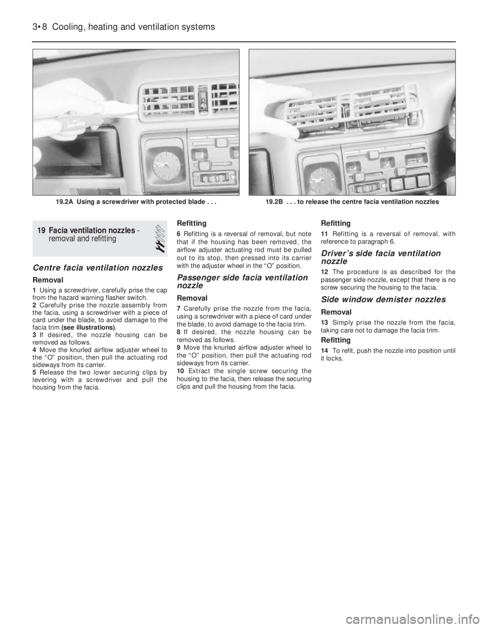
1Using a screwdriver, carefully prise the cap
from the hazard warning flasher switch.
2Carefully prise the nozzle assembly from
the facia, using a screwdriver with a piece of
card under the blade, to avoid damage to the
facia trim (see illustrations).
3If desired, the nozzle housing can be
removed as follows.
4Move the knurled airflow adjuster wheel to
the “O” position, then pull the actuating rod
sideways from its carrier.
5Release the two lower securing clips by
levering with a screwdriver and pull the
housing from the facia.
Refitting
6Refitting is a reversal of removal, but note
that if the housing has been removed, the
airflow adjuster actuating rod must be pulled
out to its stop, then pressed into its carrier
with the adjuster wheel in the “O” position.
Passenger side facia ventilation
nozzle
Removal
7Carefully prise the nozzle from the facia,
using a screwdriver with a piece of card under
the blade, to avoid damage to the facia trim.
8If desired, the nozzle housing can be
removed as follows.
9Move the knurled airflow adjuster wheel to
the “O” position, then pull the actuating rod
sideways from its carrier.
10Extract the single screw securing the
housing to the facia, then release the securing
clips and pull the housing from the facia.
Refitting
11Refitting is a reversal of removal, with
reference to paragraph 6.
Driver’s side facia ventilation
nozzle
12The procedure is as described for the
passenger side nozzle, except that there is no
screw securing the housing to the facia.
Side window demister nozzles
Removal
13Simply prise the nozzle from the facia,
taking care not to damage the facia trim.
Refitting
14To refit, push the nozzle into position until
it locks.
3•8Cooling, heating and ventilation systems
19.2A Using a screwdriver with protected blade . . .19.2B . . . to release the centre facia ventilation nozzles
Page 240 of 525
REF
Overall length: *
Saloon models . . . . . . . . . . . . . . . . . . . . . . . . . . . . . . . . . . .4432 mm
Hatchback models . . . . . . . . . . . . . . . . . . . . . . . . . . . . . . . .4352 mm
Overall width: *
All models . . . . . . . . . . . . . . . . . . . . . . . . . . . . . . . . . . . . . .1876 mm
Overall height (unladen): *
All models . . . . . . . . . . . . . . . . . . . . . . . . . . . . . . . . . . . . . .1400 mm
Wheelbase: *
All models . . . . . . . . . . . . . . . . . . . . . . . . . . . . . . . . . . . . . .2600 mm
Track:
Front: *
All models . . . . . . . . . . . . . . . . . . . . . . . . . . . . . . . . . . . .1426 mm
Rear: *
All models . . . . . . . . . . . . . . . . . . . . . . . . . . . . . . . . . . . .1423 mm
Ground clearance (minimum): *
All models . . . . . . . . . . . . . . . . . . . . . . . . . . . . . . . . . . . . . . . . .120 mm
Weights
Kerb weight: *
Dependent on model . . . . . . . . . . . . . . . . . . . . . . . . . .1098 ± 101 kg
Maximum gross vehicle weight: *
All models . . . . . . . . . . . . . . . . . . . . . . . . . . . . . . . .Refer to VIN plate
Maximum roof rack load: *
All models . . . . . . . . . . . . . . . . . . . . . . . . . . . . . . . . . . . . . . . .100 kg
Maximum towing hitch downward load: *
All models . . . . . . . . . . . . . . . . . . . . . . . . . . . . . . . . . . . . . . . . .75 kg
Maximum towing weight: *
Trailer with brakes . . . . . . . . . . . . . . . . . . . . . . . . . . . .1175 ± 175 kg
Trailer without brakes . . . . . . . . . . . . . . . . . . . . . . . . . . .550 ± 50 kg
* Exact details depend upon model and specification.
Refer to owners handbook.
Dimensions and Weights . . . . . . . . . . . . . . . . . .REF•1
Conversion Factors . . . . . . . . . . . . . . . . . . . . . . .REF•2
Buying Spare Parts . . . . . . . . . . . . . . . . . . . . . . .REF•3
Vehicle Identification . . . . . . . . . . . . . . . . . . . . . .REF•3
General Repair Procedures . . . . . . . . . . . . . . . . .REF•4
Jacking and Vehicle Support . . . . . . . . . . . . . . .REF•5Radio/cassette unit Anti-theft System . . . . . . . .REF•5
Tools and Working Facilities . . . . . . . . . . . . . . . .REF•6
MOT Test Checks . . . . . . . . . . . . . . . . . . . . . . . .REF•8
Fault Finding . . . . . . . . . . . . . . . . . . . . . . . . . . .REF•12
Glossary of Technical Terms . . . . . . . . . . . . . . .REF•20
Index . . . . . . . . . . . . . . . . . . . . . . . . . . . . . . . . .REF•25
Reference REF•1
Dimensions and Weights