warning OPEL VECTRA 1988 Service Owner's Manual
[x] Cancel search | Manufacturer: OPEL, Model Year: 1988, Model line: VECTRA, Model: OPEL VECTRA 1988Pages: 525, PDF Size: 58.26 MB
Page 71 of 525
Wiring diagrams 12•57
12
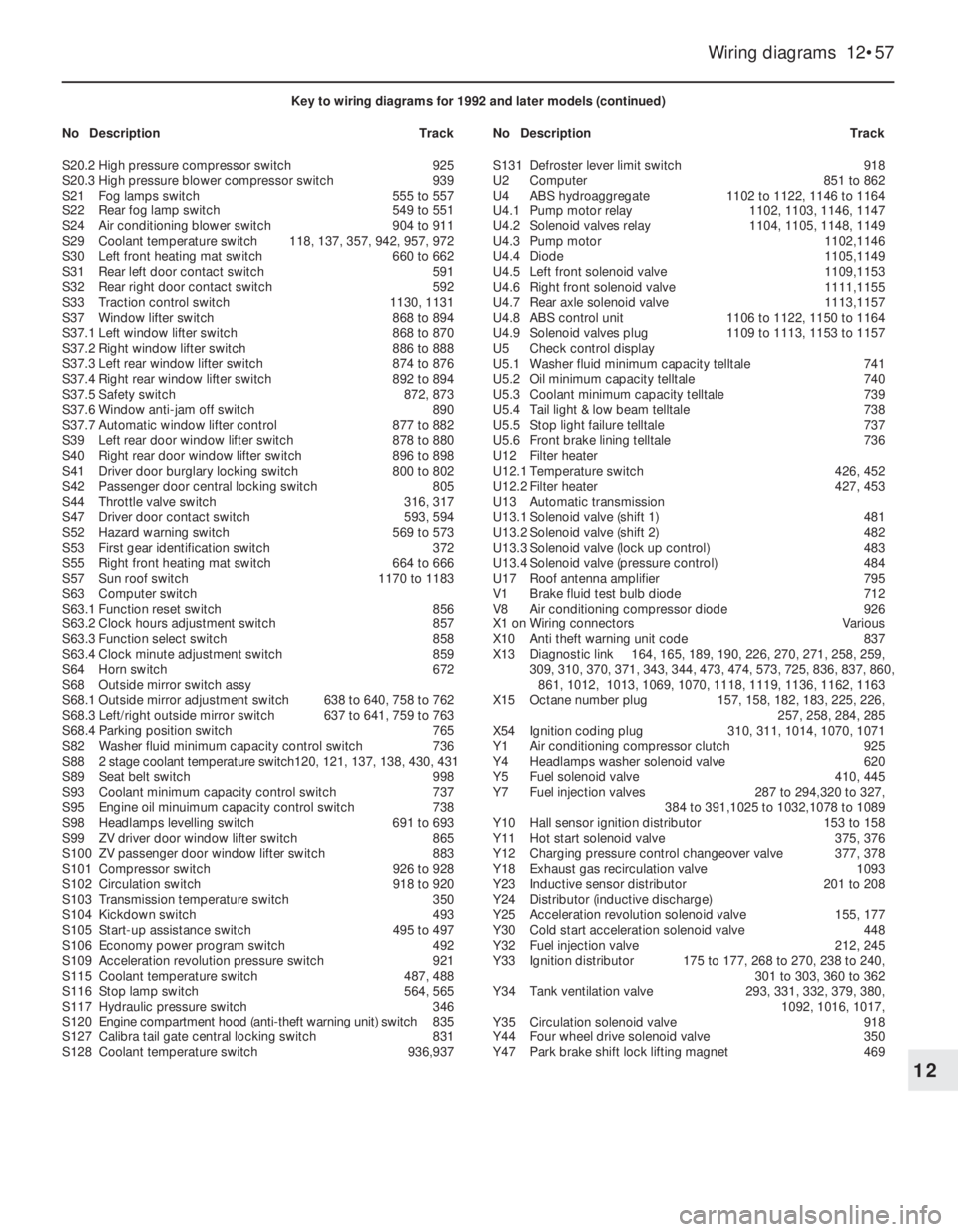
Key to wiring diagrams for 1992 and later models (continued)
NoDescriptionTrackNoDescriptionTrack
S20.2High pressure compressor switch925
S20.3High pressure blower compressor switch939
S21Fog lamps switch555 to 557
S22Rear fog lamp switch549 to 551
S24Air conditioning blower switch904 to 911
S29Coolant temperature switch118, 137, 357, 942, 957, 972
S30Left front heating mat switch660 to 662
S31Rear left door contact switch591
S32Rear right door contact switch592
S33Traction control switch1130, 1131
S37Window lifter switch868 to 894
S37.1Left window lifter switch868 to 870
S37.2Right window lifter switch886 to 888
S37.3Left rear window lifter switch874 to 876
S37.4Right rear window lifter switch892 to 894
S37.5Safety switch872, 873
S37.6Window anti-jam off switch890
S37.7Automatic window lifter control877 to 882
S39Left rear door window lifter switch878 to 880
S40Right rear door window lifter switch896 to 898
S41Driver door burglary locking switch800 to 802
S42Passenger door central locking switch805
S44Throttle valve switch316, 317
S47Driver door contact switch593, 594
S52Hazard warning switch569 to 573
S53First gear identification switch372
S55Right front heating mat switch664 to 666
S57Sun roof switch1170 to 1183
S63Computer switch
S63.1Function reset switch856
S63.2Clock hours adjustment switch857
S63.3Function select switch858
S63.4Clock minute adjustment switch859
S64Horn switch672
S68Outside mirror switch assy
S68.1Outside mirror adjustment switch638 to 640, 758 to 762
S68.3Left/right outside mirror switch637 to 641, 759 to 763
S68.4Parking position switch765
S82Washer fluid minimum capacity control switch736
S882 stage coolant temperature switch120, 121, 137, 138, 430, 431
S89Seat belt switch998
S93Coolant minimum capacity control switch737
S95Engine oil minuimum capacity control switch738
S98Headlamps levelling switch691 to 693
S99ZV driver door window lifter switch865
S100ZV passenger door window lifter switch883
S101Compressor switch926 to 928
S102Circulation switch918 to 920
S103Transmission temperature switch350
S104Kickdown switch493
S105Start-up assistance switch495 to 497
S106Economy power program switch492
S109Acceleration revolution pressure switch921
S115Coolant temperature switch487, 488
S116Stop lamp switch564, 565
S117Hydraulic pressure switch346
S120Engine compartment hood (anti-theft warning unit) switch835
S127Calibra tail gate central locking switch831
S128Coolant temperature switch936,937S131Defroster lever limit switch918
U2Computer851 to 862
U4ABS hydroaggregate1102 to 1122, 1146 to 1164
U4.1Pump motor relay1102, 1103, 1146, 1147
U4.2Solenoid valves relay1104, 1105, 1148, 1149
U4.3Pump motor1102,1146
U4.4Diode1105,1149
U4.5Left front solenoid valve1109,1153
U4.6Right front solenoid valve1111,1155
U4.7Rear axle solenoid valve1113,1157
U4.8ABS control unit1106 to 1122, 1150 to 1164
U4.9Solenoid valves plug1109 to 1113, 1153 to 1157
U5Check control display
U5.1Washer fluid minimum capacity telltale741
U5.2Oil minimum capacity telltale740
U5.3Coolant minimum capacity telltale739
U5.4Tail light & low beam telltale738
U5.5Stop light failure telltale737
U5.6Front brake lining telltale736
U12Filter heater
U12.1Temperature switch426, 452
U12.2Filter heater427, 453
U13Automatic transmission
U13.1Solenoid valve (shift 1)481
U13.2Solenoid valve (shift 2)482
U13.3Solenoid valve (lock up control)483
U13.4Solenoid valve (pressure control)484
U17Roof antenna amplifier795
V1Brake fluid test bulb diode712
V8Air conditioning compressor diode926
X1 onWiring connectorsVarious
X10Anti theft warning unit code837
X13Diagnostic link164, 165, 189, 190, 226, 270, 271, 258, 259,
309, 310, 370, 371, 343, 344, 473, 474, 573, 725, 836, 837, 860,
861, 1012, 1013, 1069, 1070, 1118, 1119, 1136, 1162, 1163
X15Octane number plug157, 158, 182, 183, 225, 226,
257, 258, 284, 285
X54Ignition coding plug310, 311, 1014, 1070, 1071
Y1Air conditioning compressor clutch925
Y4Headlamps washer solenoid valve620
Y5Fuel solenoid valve410, 445
Y7Fuel injection valves287 to 294,320 to 327,
384 to 391,1025 to 1032,1078 to 1089
Y10Hall sensor ignition distributor153 to 158
Y11Hot start solenoid valve375, 376
Y12Charging pressure control changeover valve377, 378
Y18Exhaust gas recirculation valve1093
Y23Inductive sensor distributor201 to 208
Y24Distributor (inductive discharge)
Y25Acceleration revolution solenoid valve155, 177
Y30Cold start acceleration solenoid valve 448
Y32Fuel injection valve212, 245
Y33Ignition distributor175 to 177, 268 to 270, 238 to 240,
301 to 303, 360 to 362
Y34Tank ventilation valve293, 331, 332, 379, 380,
1092, 1016, 1017,
Y35Circulation solenoid valve918
Y44Four wheel drive solenoid valve350
Y47Park brake shift lock lifting magnet469
Page 91 of 525
28The system also incorporates a separate
ignition amplifier module that transmits
amplified signals from the main system
module to trigger the HT pulse from the
ignition coil. The module is mounted on the
ignition coil’s bracket/baseplate.
29Additionally, the Motronic module
receives information from a cylinder
block-mounted knock sensor, which senses
“knocking” (or pre-ignition) just as it begins to
occur, enabling the module to retard the
ignition timing, thus preventing engine
damage.
Simtec 56.1
30This system uses increased amount of
electronic components instead of mechanical
parts as sensors and actuators with the
Simtec engine management system. This
provides more precise operating data as well
as greater problem free motoring.
31The control unit is equipped with
electronic ignition control. Called ‘Micropro-
cessor Spark Timing System, inductive
triggered’, (or MSTS-i), and means that the
mechanical high voltage distributor is no
longer needed. It is located behind the trim
panel, on the right-hand side footwell (door
pillar).
32The ignition coil is replaced by a dual
spark ignition coil, which is switched directly
by the output stages in the control unit.
33A camshaft sensor will maintain
emergency operation, should the crankshaft
inductive pulse pick-up, malfunction. These
sense TDC (‘Top Dead Centre’), crankshaft
angle and engine speed. The signals are used
by the control unit to calculate ignition point
and for fuel injection.
34The ‘hot film airflow meter’ determines the
mass of air taken in by the engine. The system
uses this information to calculate the correct
amount of fuel needed for injection in the
engine.
35The air inlet temperature sensor (NTC), is
fitted in the air inlet duct between the air
cleaner and the hot mass air flow meter.
36A controlled canister purge valve is
actuated by the system. The tank ventilation is
monitored closely with the Lambda control (or
oxygen sensor) and adaptation by the
computer within the control unit.
37A knock control system is also fitted. This
eliminates the need for octane number
adjustment, as it is performed automatically
through the control unit.
3Electrical system -
precautions
1It is necessary to take extra care when
working on the electrical system, to avoid
damage to semi-conductor devices (diodes
and transistors), and to avoid the risk of
personal injury. Along with the precautions
given in the “Safety first!” Section at the
beginning of this manual, take note of the
following points when working on the system.
2Always remove rings, watches, etc. before
working on the electrical system. Even with
the battery disconnected, discharge could
occur if a component live terminal is earthed
through a metal object. This could cause a
shock or nasty burn.
3Do not reverse the battery connections.
Components such as the alternator, or any
other component having semi-conductor
circuitry, could be irreparably damaged.
4If the engine is being started using jump
leads and a slave battery, connect the
batteries positive to positive and negative to
negative. This also applies when connecting a
battery charger.
5Never disconnect the battery terminals, or
alternator multi-plug connector, when the
engine is running.
6The battery leads and alternator wiring
must be disconnected before carrying out any
electric welding on the vehicle.
7Never use an ohmmeter of the type
incorporating a hand-cranked generator for
circuit or continuity testing.
8Engine management modules are very
sensitive components, and certain
precautions must be taken, to avoid damage
to the module when working on a vehicle
equipped with an engine management
system, as follows.
9When carrying out welding operations on
the vehicle using electric welding equipment,
the battery and alternator should be
disconnected.
10Although underbonnet-mounted modules
will tolerate normal underbonnet conditions,
they can be adversely affected by excess heat
or moisture. If using welding equipment or
pressure washing equipment near the
module, take care not to direct heat, or jets of
water or steam, at the module. If this cannot
be avoided, remove the module from the
vehicle, and protect its wiring plug with a
plastic bag.
11Before disconnecting any wiring, or
removing components, always ensure that the
ignition is switched off.
12Do not attempt to improvise fault
diagnosis procedures using a test lamp or
multimeter, as irreparable damage could be
caused to the module.13After working on ignition/engine
management system components, ensure
that all wiring is correctly reconnected before
reconnecting the battery or switching on the
ignition.
14Any ignition system that uses a
“Hall-effect” generator in the distributor,
cannot be tested. Test equipment that uses
its own power source (e.g. an ohmmeter),
when connected to the distributor or the
“Hall-effect” generator, will be damaged.
4Ignition system testing -
general
3
Note: Refer to Section 3 before proceeding.
Always switch off the ignition before
disconnecting or connecting any component
and when using a multi-meter to check
resistances. Any voltmeter or multi-meter
used to test ignition system components must
have an impedance of 10 meg ohms or
greater
1Electronic ignition system components are
normally very reliable. Most faults are far more
likely to be due to loose or dirty connections,
or to “tracking” of HT voltage due to dirt,
dampness or damaged insulation than to
component failure. Always check all wiring
thoroughly before condemning an electrical
component and work methodically to
eliminate all other possibilities before deciding
that a particular component is faulty.
2The old practice of checking for a spark by
holding the live end of a HT lead a short
distance away from the engine is not
recommended. Not only is there a high risk of
a powerful electric shock, but the ignition coil
or amplifier module will be damaged.
Similarly, never try to “diagnose” misfires by
pulling off one HT lead at a time. Note also
that the ECU is at risk if the system is
triggered with an open (i.e., not properly
earthed) HT circuit; ECU’s are very expensive
to replace, so take care!
3If you are in any doubt as to your skill and
ability to test an ignition system component or
if you do not have the required equipment,
take the vehicle to a suitably equipped
Vauxhall dealer. It is better to pay the labour
charges involved in having the vehicle
checked by an expert than to risk damage to
the system or to yourself.
4If the engine either will not turn over at all,
or only turns very slowly, check the battery
and starter motor. Connect a voltmeter across
the battery terminals (meter positive probe to
battery positive terminal) and disconnect the
ignition coil HT lead from the distributor cap
and earth. Note the voltage reading obtained
while turning over the engine on the starter for
(no more than) ten seconds. If the reading
obtained is less than approximately 9.5 volts,
check the battery, battery connections, starter
motor and charging system.
5•4Engine electrical systems
Warning: The HT voltage
generated by an electronic
ignition system is extremely
high and, in certain
circumstances, could prove fatal. Take
care to avoid receiving electric shocks
from the HT side of the ignition system.
Do not handle HT leads, or touch the
distributor or coil, when the engine is
running. If tracing faults in the HT circuit,
use well-insulated tools to manipulate live
leads
Page 118 of 525

2The sill trim panel can be removed by
simply prising it upwards to release the
securing clips from the floor (see illustration).
Refitting
3Refitting is a reversal of removal, but ensure
that the panel is correctly seated with its top
edge located under the sill weatherstrip.
Footwell side trim panel
Removal
4Release the front end of the sill trim panel
from the floor, as described previously.
5Prise the footwell side trim panel from the
footwell (see illustration). If necessary, pull
the weatherstrip from the edge of the door
aperture.
Refitting
6Refitting is a reversal of removal, but ensure
that the trim panels are correctly seated under
the weatherstrip.
Front body pillar trim panel
Removal
7Prise the trim panel from the body pillar to
release the six retaining clips. If necessary, pull
the weatherstrip from the edge of the pillar.
Refitting
8Refitting is a reversal of removal, but ensure
that the trim panel is correctly seated under
the weatherstrip.
Centre body pillar trim panels
Removal
9Remove the sill trim panel, as described
previously in this Section.
10Prise the weatherstrips from the sides of
the body pillar (see illustration).
11Pull the lower trim panel from the pillar to
release the retaining clips (see illustration).
12With the lower trim panel removed, the
upper trim panel can be withdrawn in the
same way after unbolting the upper seat belt
mounting. Prise off the trim to expose the
upper seat belt mounting bolt, then unscrew
the bolt and recover the spacer.
Refitting
13Refitting is a reversal of removal, but
ensure that the trim panels are seated
correctly under the weatherstrips.
Rear quarter trim panels
14Prise off the trim and unbolt the seat belt
upper mounting from the body pillar. Recover
the spacer.
15Pull back the weatherstrip from the rear
edge of the rear door aperture. On Hatchback
models, remove the parcel shelf.16Remove the screws securing the upper rear
quarter trim panel to the body. Note that all the
screws are of the Torx type. When working on
the right-hand side of Hatchback models, it will
be necessary to open the first-aid kit/warning
triangle cover flap in the luggage compartment
for access to some of the screws.
17Withdraw the upper seat quarter trim
panel carefully, taking care not to damage
surrounding panels (see illustration). Where
applicable, disconnect the wiring from the
loudspeaker.
18With the upper rear quarter trim panel
removed, the lower trim panel can be
removed.
19The lower rear quarter trim panel is
secured by a variety of screws, nuts and clips,
depending upon model. Removal and refitting
of the panel is self-explanatory, remembering
the points made in Section 35. Note that the
rubber stop must be removed from the seat
catch before the trim panel can be withdrawn
(see illustrations).
Luggage compartment rear trim
panel
20Prise the trim panel from the rear of the
luggage compartment to release the securing
clips.
21Refitting is a reversal of removal.
Tailgate trim panels (Hatchback
models)
22The tailgate trim panels are secured by
screws, and removal and refitting are
self-explanatory. Note that the lower side
panel securing screws also secure the rear
panel.
Bodywork and fittings 11•15
36.10 Pull the weatherstrip from the sides
of the body pillar . . .
36.19B Withdrawing the lower rear quarter
trim panel - Hatchback model36.19A Removing the rubber stop from the
seat catch36.17 Withdrawing the upper rear quarter
trim panel - Hatchback model
36.11 . . . then pull the lower trim panel
from the pillar
36.5 Removing the driver’s footwell side
trim panel36.2 Sill trim panel removed to expose
securing clips
11
Page 121 of 525

Glovebox assembly
Removal
32Carefully prise the side trim panels from
the passenger’s oddments tray, using a
screwdriver (see illustration).
33Open the glovebox, then using a
screwdriver, release the two lower retaining
clips at the rear of the oddments tray, and
withdraw the oddments tray from the facia
(see illustrations).
34Where applicable, prise out the glovebox
lamp, and disconnect the wiring (see
illustration).
35Extract the two upper and two lower
securing screws, then withdraw the glovebox
assembly from the facia (see illustrations).
Refitting
36Refitting is a reversal of removal, but
where applicable, feed the wiring through the
glovebox lamp aperture as the assembly is
offered into position.
38Centre console - removal and
refitting
2
Rear section
Removal
1Prise the trim panel from the front of the
rear centre console section to expose the
front securing screw (see illustration).
2Extract the front securing screw (see
illustration).3Release the gaiter from the rear of the
handbrake lever grip, then pull the grip from
the front of the handbrake lever (see
illustration).
11•18Bodywork and fittings
37.30A Slide the radio support tray from
the facia . . .37.32 Prise the side trim panels from the
oddments tray . . .
37.35C . . . then withdraw the glovebox37.35B . . . and lower glovebox securing
screws . . .37.35A Extract the upper . . .
37.34 Prise out the glovebox lamp and
disconnect the wiring37.33B . . . and withdraw the oddments
tray37.33A . . . then release the lower retaining
clips . . .
37.30B . . . then disconnect the wiring and
aerial plugs
38.1 Prise the trim panel from the centre
console . . .
Warning: If an airbag is fitted,
read the warning in Chapter 12,
before starting work.
Page 123 of 525
Refitting
10Refitting is a reversal of removal, but
where applicable, refit the sunroof crank drive,
as described in Section 34.
40Seats (without tensioners) -
removal and refitting
3
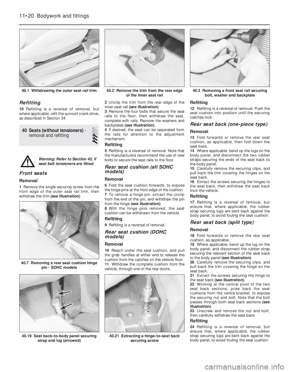
Front seats
Removal
1Remove the single securing screw from the
front edge of the outer seat rail trim, then
withdraw the trim (see illustration).2Unclip the trim from the rear edge of the
inner seat rail (see illustration).
3Remove the four bolts that secure the seat
rails to the floor, then withdraw the seat,
complete with rails. Recover the washers and
backplates (see illustration).
4If desired, the seat can be separated from
the rails for attention to the adjustment
mechanism.
Refitting
5Refitting is a reversal of removal. Note that
the manufacturers recommend the use of new
bolts to secure the seat rails to the floor.
Rear seat cushion (all SOHC
models)
Removal
6Fold the seat cushion forwards, to expose
the hinge pins at the front edge of the cushion.
7To remove a hinge pin, extract the circlip
from the end of the pin, and withdraw the pin
from the hinge (see illustration).
8With the hinge pins removed, the seat
cushion can be withdrawn from the vehicle.
Refitting
9Refitting is a reversal of removal.
Rear seat cushion (DOHC
models)
Removal
10Reach under the seat cushion, and pull
the grab handles at either end to release the
cushion from the catches on the vehicle floor.
11Withdraw the complete cushion from the
vehicle, through one of the rear doors.
Refitting
12Refitting is a reversal of removal. Push the
seat cushion into position until the securing
catches lock.
Rear seat back (one-piece type)
Removal
13Fold forwards or remove the rear seat
cushion, as applicable, then fold down the
seat back.
14Where applicable, bend up the lugs on the
body panel, and disconnect the two rubber
straps securing the ends of the seat back to
the body panel.
15Carefully remove the securing clips, and
pull back the trim covering the hinges on the
seat back.
16Extract the screws securing the hinges to
the seat back, then withdraw the seat back
from the vehicle.
Refitting
17Refitting is a reversal of removal, but
ensure that, where applicable, the rubber
strap securing lugs are bent back against the
body panel, to avoid fouling the seat cushion.
Rear seat back (split type)
Removal
18Fold forwards or remove the rear seat
cushion, as applicable.
19Where applicable, bend up the lug on the
body panel, and disconnect the rubber strap
securing the relevant section of the seat back
to the body panel (see illustration).
20Carefully remove the securing clips, and
pull back the trim covering the hinge on the
seat back.
21Extract the screws securing the hinge to
the seat back (see illustration).
22Working at the central pivot of the two
seat back sections, prise back the seat
cushions from the centre bracket, to expose
the securing nut and bolt. Note that the bolt
passes through both seat back sections (see
illustration).
23Unscrew and remove the nut and bolt,
then carefully withdraw the seat back.
Refitting
24Refitting is a reversal of removal, but
ensure that, where applicable, the rubber
strap securing lugs are bent back against the
body panel, to avoid fouling the seat cushion.
11•20Bodywork and fittings
40.1 Withdrawing the outer seat rail trim40.3 Removing a front seat rail securing
bolt, washer and backplate
40.7 Removing a rear seat cushion hinge
pin - SOHC models
40.21 Extracting a hinge-to-seat back
securing screw40.19 Seat back-to-body panel securing
strap and lug (arrowed)
40.2 Remove the trim from the rear edge
of the inner seat rail
Warning: Refer to Section 43, if
seat belt tensioners are fitted.
Page 124 of 525

41Seat belts - removal and
refitting
3
Note: For details on mechanical seat belt
tensioners, refer to Section 42.
Front seat belt
Removal
1Open both front and rear doors, and prise
the weatherstrips from the edge of the centre
body pillar.
2Prise off the pillar lower trim panel to
expose the inertia reel unit.
3Unscrew the securing bolt, and tilt the
inertia reel unit from the body pillar (see
illustration).
4Prise off the trim and unbolt the seat belt
upper mounting from the body pillar. Recover
the spacer.
5Similarly, unbolt the seat belt lower
mounting, then withdraw the seat belt
assembly from the vehicle.
6If desired, the seat belt stalk can be
unbolted from the seat frame, and the upper
mounting height adjuster (where applicable)
can be unbolted from the body pillar (Torx
bolts), after prising off the pillar upper trim
panel.
Refitting
7Refitting is a reversal of removal, but note
that, when refitting the height adjuster, the
arrows should be uppermost, pointingtowards the vehicle roof. Ensure that the belt
is fitted untwisted.
Rear seat belt
Removal
8Fold the rear seat cushion forwards, or
remove it, as applicable, for access to the
seat belt lower mountings. Prise up the carpet
to expose the mounting bolts, and unscrew
the relevant bolt(s) from the floor (see
illustrations).
9Prise off the trim, and unbolt the seat belt
upper mounting from the body pillar. Recover
the spacer (see illustration).
10Open the relevant rear door, and pull back
the weatherstrip from the rear of the door
aperture.
11On Hatchback models, remove the
screws securing the upper rear quarter trim
panel to the body. Note that all the screws are
of the Torx type, and when working on the
right-hand side, it will be necessary to open
the first-aid kit/warning triangle cover flap in
the luggage compartment for access to some
of the screws. Withdraw the trim panel
carefully, taking care not to damage
surrounding panels.
12Detach the front edge of the lower rear
quarter trim panel from the body. The panel is
secured by clips on Saloon models, and by
screws on Hatchback models.
13Pull the lower rear quarter trim panel away
from the body sufficiently to gain access to
the seat belt inertia reel unit (see illustration).14Unscrew the securing bolt, and lift the
inertia reel unit from the body panel, then
withdraw the seat belt assembly from the
vehicle.
15If desired, the upper seat belt mounting
height adjuster can be unbolted from the body
pillar (Torx bolts), after removing the upper
rear quarter trim panel (see illustration).
Refitting
16Refitting is a reversal of removal, but note
that, when refitting the height adjuster (where
applicable), the arrows should be uppermost,
pointing towards the vehicle roof. Ensure that
the belt is fitted untwisted.
42Seat belt tensioners - general
5
1All 1993-onwards Cavalier models are
equipped with mechanical front seat belt
tensioners which automatically tighten the
front seat belts in the event of a head-on
collision. The mechanically operated device
ensures that the seat belt remains close to the
body, thus preventing the wearer from sliding
out, under the belt, during impact (see
illustration).
2The tensioner system consists of a powerful
preloaded spring, contained in a cylinder,
which is released in the event of severe
impact. The spring pulls back the seat belt by
means of a bowden cable and fulcrum
mechanism attached to the belt stalk,
mounted on the seat frame.
Bodywork and fittings 11•21
41.8 Rear seat belt lower side mounting -
Hatchback model
41.15 Upper rear quarter trim panel
removed, to expose upper seat belt
mounting height adjuster41.13 Rear seat belt inertia reel unit
location - Hatchback model41.9 Removing a rear seat belt upper
mounting from the body pillar - Hatchback
model
41.3 Unscrewing a front seat belt inertia
reel securing bolt40.22 Rear seat cushion pulled back to
expose seat back hinge nut and bolt - split
type rear seat back
11
Page 125 of 525

3The tensioner assembly, fitted to the
underside of the front seat, is maintenance
free and, once triggered, must be replaced as
a complete unit.
4Due to the specialist safety related nature
of the seat belt tensioner system, replacement
must be entrusted to a suitably equipped
Vauxhall dealer.
43Front seats (with seat belt
tensioners) -removal and
refitting
3
Removal
1Remove the single securing screw from the
front edge of the outer seat rail trim, release
the rear retaining lug and remove the trim
rearwards.
2Unclip the trim from the rear edge of the
inner seat rail.3Locate the plastic safety fork for the seat
belt tensioner, which is usually taped to the
outside of the tensioner spring cylinder.
4Insert the fork into the aperture provided at
the rear of the spring cylinder, ensuring that
the fork engages securely (see illustration).
5Remove the four bolts which secure the
seat rails to the floor, then withdraw the seat
complete with rails (see illustration). Recover
the washers and backplates.
6Seek the advice of a Vauxhall dealer if there
is any doubt about the condition of the seat
belt tensioner assembly.
Refitting
7Refitting is a reversal of removal. Note that
the manufacturers recommend the use of new
bolts to secure the seat rails to the floor.
Tighten the bolts to the specified torque
wrench settings (see Specifications) in the
order - rear inner, front inner, rear outer, front
outer.
11•22Bodywork and fittings
42.1 Mechanical seat belt tensioner system
1 Spring2 Bowden cable3 Fulcrum mechanism
43.5 Front outer seat rail fixings
1 Securing bolt
2 Seat belt tensioner safety fork (inserted
in the spring cylinder)43.4 Inserting the safety fork into the
aperture in the seat belt tensioner spring
cylinder
Warning: The seat belt
tensioners fitted to the front
seat assemblies may cause
injury if triggered inadvertently.
Before carrying out any work on the front
seats, a safety fork must be inserted into
the seat belt tensioner cylinder, to prevent
the possibility of the tensioner being
triggered (see paragraphs 7 and 8 below).
Seats should always be transported and
installed with the safety fork in place. If a
seat is to be disposed of, the tensioner
must be triggered before the seat is
removed from the vehicle, by inserting the
safety fork, and striking the tensioner
cylinder sharply with a hammer. If the
tensioner has been triggered due to a
sudden impact or accident, the unit must
be renewed, as it cannot be reset. Due to
safety considerations, tensioner renewal
should be entrusted to a Vauxhall dealer.
Page 147 of 525
16If adjustment is necessary, slacken the
locknut, turn the fork to give the specified
dimension, then tighten the locknut.
17Where applicable, coat the contact faces
of the servo and the mounting bracket with
sealing compound, then refit the bracket to
the servo, and tighten the securing nuts to the
specified torque.
18Coat the threads of the servo securing
bolts with locking fluid, then fit the servo to
the bulkhead and tighten the securing bolts.
19Refit the securing bolt cover plugs to the
cowl panel.
20Refit the master cylinder to the servo, and
tighten the securing nuts to the specified
torque.
21Reconnect the vacuum pipe to the servo.
22Refit the coolant expansion tank, as
described in Chapter 3.
23Refit the windscreen wiper motor and
linkage as described in Chapter 12, then refit
the windscreen cowl panel.
24Further refitting is a reversal of removal.
On completion, test the operation of the
servo, as described in Section 18.
20ABS hydraulic modulator -
removal and refitting
4
Note: Refer to Section 2, and the note at the
beginning of Section 3, before proceeding
Removal
1Disconnect the battery negative lead.
2Remove the brake fluid reservoir cap, and
secure a piece of polythene over the filler
neck with a rubber band, or by refitting the
cap. This will reduce the loss of fluid during
the following procedure.
3Remove the securing screw, and withdraw
the plastic cover from the hydraulic
modulator.
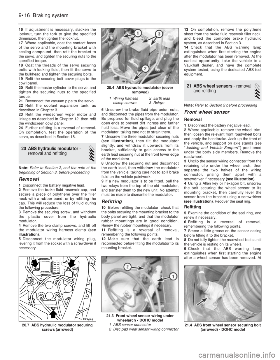
4Remove the two clamp screws, and lift off
the modulator wiring harness clamp (see
illustration).
5Disconnect the modulator wiring plug,
levering it from the socket with a screwdriver if
necessary.6Unscrew the brake fluid pipe union nuts,
and disconnect the pipes from the modulator.
Be prepared for fluid spillage, and plug the
open ends to prevent dirt ingress and further
fluid loss. Move the pipes just clear of the
modulator, taking care not to strain them.
7Unscrew the three modulator securing nuts
(see illustration), then tilt the modulator
slightly, and withdraw it upwards from its
bracket, sufficiently to gain access to the
earth lead securing nut at the front lower edge
of the modulator.
8Unscrew the securing nut and disconnect
the earth lead, then withdraw the modulator
from the vehicle, taking care not to spill brake
fluid on the vehicle paintwork.
9If a new modulator is to be fitted, pull the
two relays from the top of the old modulator,
and transfer them to the new unit. No attempt
must be made to dismantle the modulator.
Refitting
10Before refitting the modulator, check that
the bolts securing the mounting bracket to the
body panel are tight, and that the modulator
rubber mountings are in good condition.
Renew the rubber mountings if necessary.
11Refitting is a reversal of removal,
remembering the following points.
12Make sure that the earth lead is
reconnected before fitting the modulator to its
mounting bracket.13On completion, remove the polythene
sheet from the brake fluid reservoir filler neck,
and bleed the complete brake hydraulic
system, as described in Section 3.
14Check that the ABS warning lamp
extinguishes when first starting the engine
after the modulator has been removed. At the
earliest opportunity, take the vehicle to a
Vauxhall dealer, and have the complete
system tested, using the dedicated ABS test
equipment.
21ABS wheel sensors - removal
and refitting
3
Note: Refer to Section 2 before proceeding
Front wheel sensor
Removal
1Disconnect the battery negative lead.
2Where applicable, remove the wheel trim,
then loosen the relevant front roadwheel bolts
and apply the handbrake. Jack up the front of
the vehicle, and support on axle stands (see
“Jacking and Vehicle Support”) positioned
under the body side members. Remove the
roadwheel.
3Unclip the sensor wiring connector from the
retaining clip under the wheel arch, then
separate the two halves of the wiring
connector, prising them apart with a
screwdriver if necessary (see illustration).
4Using a Allen key or hexagon bit, unscrew
the bolt securing the wheel sensor to its
mounting bracket, then carefully lever the
sensor from the bracket using a screwdriver
(see illustration). Recover the seal ring.
Refitting
5Examine the condition of the seal ring, and
renew if necessary.
6Refitting is a reversal of removal,
remembering the following points.
7Smear a little grease on the sensor casing
before fitting it to the bracket.
8Do not fully tighten the roadwheel bolts until
the vehicle is resting on its wheels.
9Check that the ABS warning lamp
extinguishes when first starting the engine
after a wheel sensor has been removed. At
9•16Braking system
20.4 ABS hydraulic modulator (cover
removed)
1 Wiring harness
clamp screws2 Earth lead
3 Relays
21.3 Front wheel sensor wiring under
wheelarch - DOHC model
1 ABS sensor connector
2 Disc pad wear sensor wiring connector
21.4 ABS front wheel sensor securing bolt
(arrowed) - DOHC model20.7 ABS hydraulic modulator securing
screws (arrowed)
Page 148 of 525
the earliest opportunity, take the vehicle to a
Vauxhall dealer, and have the complete
system tested, using the dedicated ABS test
equipment.
Rear wheel sensor
Removal
10Disconnect the battery negative lead.
11Where applicable, remove the wheel trim,
then loosen the relevant rear roadwheel bolts
and chock the front wheels. Jack up the rear
of the vehicle, and support on axle stands
(see “Jacking and Vehicle Support”)
positioned under the body side members.
Remove the roadwheel.
12Unclip the sensor wiring connector from
the retaining clip on the rear underbody, then
separate the two halves of the wiring
connector, prising them apart with a
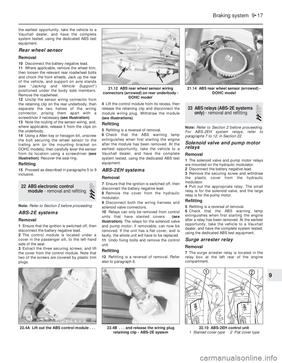
screwdriver if necessary (see illustration).
13Note the routing of the sensor wiring, and,
where applicable, release it from the clips on
the underbody.
14Using a Allen key or hexagon bit, unscrew
the bolt securing the wheel sensor to the
trailing arm (or the mounting bracket on
DOHC models), then carefully lever the sensor
from its location using a screwdriver (see
illustration). Recover the seal ring.
Refitting
15Proceed as described in paragraphs 5 to 9
inclusive.
22ABS electronic control
module - removal and refitting
3
Note: Refer to Section 2 before proceeding
ABS-2E systems
Removal
1Ensure that the ignition is switched off, then
disconnect the battery negative lead.
2The control module is located under a
cover in the passenger sill, to the left-hand
side of the seat.
3Extract the three securing screws, and lift
the cover from the control module. Note that
two of the screws are covered by plastic trim
plugs. 4Lift the control module from its recess, then
release the retaining clip and disconnect the
module wiring plug. Withdraw the module
(see illustrations).
Refitting
5Refitting is a reversal of removal.
6Check that the ABS warning lamp
extinguishes when first starting the engine
after the module has been removed. At the
earliest opportunity, take the vehicle to a
Vauxhall dealer, and have the complete
system tested, using the dedicated ABS test
equipment.
ABS-2EH systems
Removal
7Ensure that the ignition is switched off, then
disconnect the battery negative lead.
8Remove the cover from the hydraulic
modulator.
9Disconnect both the wiring harness and
solenoid valve connectors.
10Relays can only be removed from control
units that have slanted covers (see
illustration). The relays for the solenoid valve
and pump motor, if removable, can now be
removed. If the unit has a flat cover, and is
faulty, the whole unit will have to be replaced.
11Undo fixing bolts and remove the control
unit.
Refitting
12Refitting is a reversal of removal. Refer
also to paragraph 6.
23ABS relays (ABS-2E systems
only) - removal and refitting
2
Note: Refer to Section 2 before proceeding.
For ABS-2EH system relays, refer to
paragraphs 7 to 12, in Section 22.
Solenoid valve and pump motor
relays
Removal
1The solenoid valve and pump motor relays
are mounted on the hydraulic modulator.
2Disconnect the battery negative lead.
3Remove the securing screw and withdraw
the plastic cover from the hydraulic
modulator.
4Pull out the appropriate relay. The small
relay is for the solenoid valve, and the large
relay is for the pump motor.
Refitting
5Refitting is a reversal of removal.
6Check that the ABS warning lamp
extinguishes when first starting the engine
after a relay has been removed. At the earliest
opportunity, take the vehicle to a Vauxhall
dealer, and have the complete system tested,
using the dedicated ABS test equipment.
Surge arrester relay
Removal
7The surge arrester relay is located in the
relay box at the left rear of the engine
compartment.
Braking system 9•17
22.4A Lift out the ABS control module . . .22.10 ABS-2EH control unit
1 Slanted cover type 2 Flat cover type22.4B . . . and release the wiring plug
retaining clip - ABS-2E system
21.14 ABS rear wheel sensor (arrowed) -
DOHC model21.12 ABS rear wheel sensor wiring
connectors (arrowed) on rear underbody -
DOHC model`
9
Page 151 of 525
Refitting
17Proceed as described in paragraphs 11
to 15 inclusive.
Models with rear disc brakes
(SOHC)
General
18The procedure is as described for models
with rear drum brakes, remembering the
following points.
19Ignore the references to removal and
refitting of the brake drum.
20Note that there is no lockplate securing
the handbrake cable to the brake backplate,
but the return spring must be unhooked from
the cable end.
21On models with a catalytic converter,
when removing the longer cable, unscrew the
four securing nuts and withdraw the exhaust
centre box heat shield by carefully sliding it
round the centre box.
DOHC models
Removal
22The left and right-hand handbrake cables,
and the equaliser yoke, are removed as an
assembly on DOHC models.
23Loosen the rear roadwheel bolts, then
chock the front wheels, jack up the rear of the
vehicle, and support securely on axle stands
(see “Jacking and Vehicle Support”)
positioned under the body side members.
Remove the roadwheels.
24Note the routing of the handbrake cables,
as an aid to refitting.
25On models with a catalytic converter,
unscrew the four securing nuts and withdraw
the exhaust centre box heat shield by
carefully sliding it round the centre box.
26Note the length of exposed thread at the
cable equaliser yoke, then unscrew the
securing nut and disconnect the equaliser
yoke from the handbrake lever operating rod.
27Unhook the cable ends from the brake
shoe operating levers and the return springs
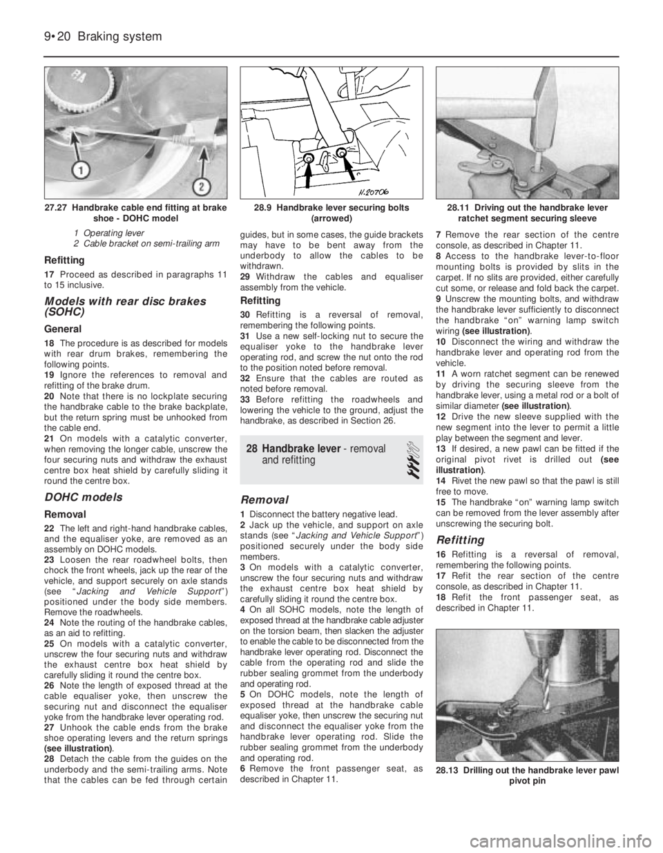
(see illustration).
28Detach the cable from the guides on the
underbody and the semi-trailing arms. Note
that the cables can be fed through certainguides, but in some cases, the guide brackets
may have to be bent away from the
underbody to allow the cables to be
withdrawn.
29Withdraw the cables and equaliser
assembly from the vehicle.
Refitting
30Refitting is a reversal of removal,
remembering the following points.
31Use a new self-locking nut to secure the
equaliser yoke to the handbrake lever
operating rod, and screw the nut onto the rod
to the position noted before removal.
32Ensure that the cables are routed as
noted before removal.
33Before refitting the roadwheels and
lowering the vehicle to the ground, adjust the
handbrake, as described in Section 26.
28Handbrake lever - removal
and refitting
3
Removal
1Disconnect the battery negative lead.
2Jack up the vehicle, and support on axle
stands (see “Jacking and Vehicle Support”)
positioned securely under the body side
members.
3On models with a catalytic converter,
unscrew the four securing nuts and withdraw
the exhaust centre box heat shield by
carefully sliding it round the centre box.
4On all SOHC models, note the length of
exposed thread at the handbrake cable adjuster
on the torsion beam, then slacken the adjuster
to enable the cable to be disconnected from the
handbrake lever operating rod. Disconnect the
cable from the operating rod and slide the
rubber sealing grommet from the underbody
and operating rod.
5On DOHC models, note the length of
exposed thread at the handbrake cable
equaliser yoke, then unscrew the securing nut
and disconnect the equaliser yoke from the
handbrake lever operating rod. Slide the
rubber sealing grommet from the underbody
and operating rod.
6Remove the front passenger seat, as
described in Chapter 11.7Remove the rear section of the centre
console, as described in Chapter 11.
8Access to the handbrake lever-to-floor
mounting bolts is provided by slits in the
carpet. If no slits are provided, either carefully
cut some, or release and fold back the carpet.
9Unscrew the mounting bolts, and withdraw
the handbrake lever sufficiently to disconnect
the handbrake “on” warning lamp switch
wiring (see illustration).
10Disconnect the wiring and withdraw the
handbrake lever and operating rod from the
vehicle.
11A worn ratchet segment can be renewed
by driving the securing sleeve from the
handbrake lever, using a metal rod or a bolt of
similar diameter (see illustration).
12Drive the new sleeve supplied with the
new segment into the lever to permit a little
play between the segment and lever.
13If desired, a new pawl can be fitted if the
original pivot rivet is drilled out (see
illustration).
14Rivet the new pawl so that the pawl is still
free to move.
15The handbrake “on” warning lamp switch
can be removed from the lever assembly after
unscrewing the securing bolt.
Refitting
16Refitting is a reversal of removal,
remembering the following points.
17Refit the rear section of the centre
console, as described in Chapter 11.
18Refit the front passenger seat, as
described in Chapter 11.
9•20Braking system
28.13 Drilling out the handbrake lever pawl
pivot pin
28.11 Driving out the handbrake lever
ratchet segment securing sleeve28.9 Handbrake lever securing bolts
(arrowed)27.27 Handbrake cable end fitting at brake
shoe - DOHC model
1 Operating lever
2 Cable bracket on semi-trailing arm