tyre pressure OPEL VECTRA 1988 Service Repair Manual
[x] Cancel search | Manufacturer: OPEL, Model Year: 1988, Model line: VECTRA, Model: OPEL VECTRA 1988Pages: 525, PDF Size: 58.26 MB
Page 134 of 525
5If the ‘ABS’ symbol, in the instrument panel
stays lit after approximately 4 seconds, or if it
comes on sporadically or stays on whilst
driving, there is a fault in the system. Should
this occur, it is recommended that a complete
test is carried out by a Vauxhall dealer, who
will have the necessary specialist diagnostic
equipment. Due to the special equipment
required, it is not practical for the DIY
mechanic to carry out the test procedure.
6To prevent possible damage to the
electronic control unit, always disconnect the
control unit wiring plug before carrying out
electrical welding work.
7It is recommended that the control unit is
removed if the vehicle is being subjected to
high temperatures, like for instance, during
certain paint-drying processes.
8If using steam cleaning equipment, do not
aim the water/steam jet directly at the control
unit.
9Do not disconnect the control unit wiring
plug with the ignition switched on.
10Do not use a battery booster to start the
engine.
11After working on the ABS components,
ensure that all wiring plugs are correctly
reconnected, and have the complete system
tested by a Vauxhall dealer, at the earliest
opportunity.
12All models up to 1991 that were fitted with
ABS, used the ABS-2E system. From 1992
onwards an ABS-2EH system was fitted,
which can be identified by the location of the
electronic control module, which is bolted to
the hydraulic modulator.
13The main differences between the two
systems are in the electrical components and
circuits, the most obvious of these being
omission of the surge arrester relay on the
2EH system.
3Hydraulic system - bleeding
2
General
1If any of the hydraulic components in the
braking system have been removed or
disconnected, or if the fluid level in the
reservoir has been allowed to fall appreciably,
it is certain that air will have entered into the
system. The removal of all this air from the
hydraulic system is essential if the brakes are
to function correctly, and the process of
removing it is known as bleeding.
2Where an operation has only affected one
circuit of the hydraulic system (the system issplit diagonally on non-ABS models, and front
and rear on ABS models), then it will only be
necessary to bleed the relevant circuit. If the
master cylinder has been disconnected and
reconnected, or the fluid level has been
allowed to fall appreciably, then the complete
system must be bled.
3One of three methods can be used to bleed
the system, although Vauxhall recommend
the use of a pressure bleeding kit.
Bleeding - two-man method
4Obtain a clean jar, and a length of rubber or
plastic bleed tubing that will fit the bleed
screws tightly. The help of an assistant will be
required.
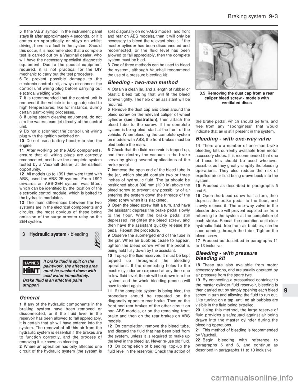
5Remove the dust cap and clean around the
bleed screw on the relevant caliper of wheel
cylinder (see illustration), then attach the
bleed tube to the screw. If the complete
system is being bled, start at the front of the
vehicle. When bleeding the complete system
on models with ABS, the front brakes must be
bled before the rears.
6Check that the fluid reservoir is topped up,
and then destroy the vacuum in the brake
servo by giving several applications of the
brake pedal.
7Immerse the open end of the bleed tube in
the jar, which should contain two or three
inches of hydraulic fluid. The jar should be
positioned about 300 mm (12.0 in) above the
bleed screw to prevent any possibility of air
entering the system down the threads of the
bleed screw when it is slackened.
8Open the bleed screw half a turn, and have
the assistant depress the brake pedal slowly
to the floor. With the brake pedal still
depressed, retighten the bleed screw, and
then have the assistant quickly release the
pedal. Repeat the procedure.
9Observe the submerged end of the tube in
the jar. When air bubbles cease to appear,
tighten the bleed screw when the pedal is
being held fully down by the assistant.
10Top-up the fluid reservoir. It must be kept
topped up throughout the bleeding
operations. If the connecting holes to the
master cylinder are exposed at any time due
to low fluid level, the air will be drawn into the
system, and the whole bleeding process will
have to start again.
11If the complete system is being bled, the
procedure should be repeated on the
diagonally opposite rear brake. Then on the
front and rear brakes of the other circuit on
non-ABS models, or on the remaining front
brake and then on the rear brakes on ABS
models.
12On completion, remove the bleed tube,
and discard the fluid that has been bled from
the system, unless it is required to make up
the level in the bleed jar. Never re-use old fluid.
13On completion of bleeding, top-up the
fluid level in the reservoir. Check the action ofthe brake pedal, which should be firm, and
free from any “sponginess” that would
indicate that air is still present in the system.
Bleeding - with one-way valve
14There are a number of one-man brake
bleeding kits currently available from motor
accessory shops. It is recommended that one
of these kits should be used whenever
possible, as they greatly simplify the bleeding
operations. They also reduce the risk of
expelled air or fluid being drawn back into the
system.
15Proceed as described in paragraphs 5
and 6.
16Open the bleed screw half a turn, then
depress the brake pedal to the floor, and
slowly release it. The one-way valve in the
bleeder device will prevent expelled air from
returning to the system at the completion of
each stroke. Repeat the operation until clear
hydraulic fluid, free from air bubbles, can be
seen coming through the tube. Tighten the
bleed screw.
17Proceed as described in paragraphs 11
to 13 inclusive.
Bleeding - with pressure
bleeding kit
18These are also available from motor
accessory shops, and are usually operated by
air pressure from the spare tyre.
19By connecting a pressurised container to
the master cylinder fluid reservoir, bleeding is
then carried out by simply opening each bleed
screw in turn and allowing the fluid to run out.
Like turning on a tap, until no air bubbles are
visible in the fluid being expelled.
20Using this method, the large reserve of
fluid provides a safeguard against air being
drawn into the master cylinder during the
bleeding operations.
21This method of bleeding is recommended
by Vauxhall.
22Begin bleeding with reference to
paragraphs 5 and 6, and continue as
described in paragraphs 11 to 13 inclusive.
Braking system 9•3
3.5 Removing the dust cap from a rear
caliper bleed screw - models with
ventilated discs
9
If brake fluid is spilt on the
paintwork, the affected area
must be washed down with
cold water immediately.
Brake fluid is an effective paint
stripper!
Page 174 of 525
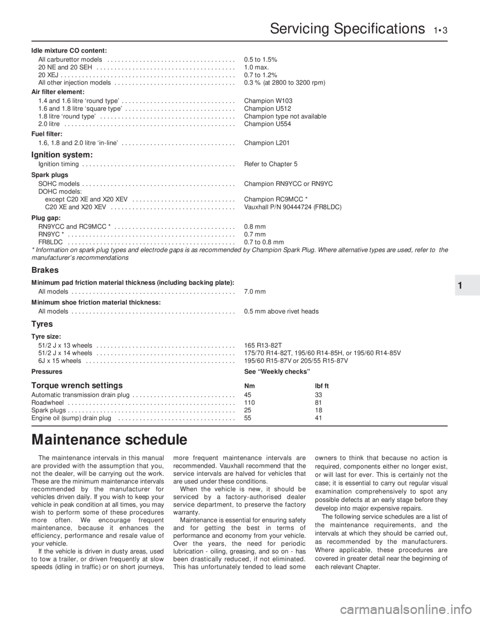
Idle mixture CO content:
All carburettor models . . . . . . . . . . . . . . . . . . . . . . . . . . . . . . . . . . . .0.5 to 1.5%
20 NE and 20 SEH . . . . . . . . . . . . . . . . . . . . . . . . . . . . . . . . . . . . . . .1.0 max.
20 XEJ . . . . . . . . . . . . . . . . . . . . . . . . . . . . . . . . . . . . . . . . . . . . . . . . .0.7 to 1.2%
All other injection models . . . . . . . . . . . . . . . . . . . . . . . . . . . . . . . . . .0.3 % (at 2800 to 3200 rpm)
Air filter element:
1.4 and 1.6 litre ‘round type’ . . . . . . . . . . . . . . . . . . . . . . . . . . . . . . . .Champion W103
1.6 and 1.8 litre ‘square type’ . . . . . . . . . . . . . . . . . . . . . . . . . . . . . . .Champion U512
1.8 litre ‘round type’ . . . . . . . . . . . . . . . . . . . . . . . . . . . . . . . . . . . . . .Champion type not available
2.0 litre . . . . . . . . . . . . . . . . . . . . . . . . . . . . . . . . . . . . . . . . . . . . . . . .Champion U554
Fuel filter:
1.6, 1.8 and 2.0 litre ‘in-line’ . . . . . . . . . . . . . . . . . . . . . . . . . . . . . . . .Champion L201
Ignition system:
Ignition timing . . . . . . . . . . . . . . . . . . . . . . . . . . . . . . . . . . . . . . . . . . .Refer to Chapter 5
Spark plugs
SOHC models . . . . . . . . . . . . . . . . . . . . . . . . . . . . . . . . . . . . . . . . . . .Champion RN9YCC or RN9YC
DOHC models:
except C20 XE and X20 XEV . . . . . . . . . . . . . . . . . . . . . . . . . . . . .Champion RC9MCC *
C20 XE and X20 XEV . . . . . . . . . . . . . . . . . . . . . . . . . . . . . . . . . . .Vauxhall P/N 90444724 (FR8LDC)
Plug gap:
RN9YCC and RC9MCC * . . . . . . . . . . . . . . . . . . . . . . . . . . . . . . . . . .0.8 mm
RN9YC * . . . . . . . . . . . . . . . . . . . . . . . . . . . . . . . . . . . . . . . . . . . . . . .0.7 mm
FR8LDC . . . . . . . . . . . . . . . . . . . . . . . . . . . . . . . . . . . . . . . . . . . . . . .0.7 to 0.8 mm
* Information on spark plug types and electrode gaps is as recommended by Champion Spark Plug. Where alternative types are used, refer to the
manufacturer’s recommendations
Brakes
Minimum pad friction material thickness (including backing plate):
All models . . . . . . . . . . . . . . . . . . . . . . . . . . . . . . . . . . . . . . . . . . . . . .7.0 mm
Minimum shoe friction material thickness:
All models . . . . . . . . . . . . . . . . . . . . . . . . . . . . . . . . . . . . . . . . . . . . . .0.5 mm above rivet heads
Tyres
Tyre size:
51/2 J x 13 wheels . . . . . . . . . . . . . . . . . . . . . . . . . . . . . . . . . . . . . . .165 R13-82T
51/2 J x 14 wheels . . . . . . . . . . . . . . . . . . . . . . . . . . . . . . . . . . . . . . .175/70 R14-82T, 195/60 R14-85H, or 195/60 R14-85V
6J x 15 wheels . . . . . . . . . . . . . . . . . . . . . . . . . . . . . . . . . . . . . . . . . .195/60 R15-87V or 205/55 R15-87V
PressuresSee “Weekly checks”
Torque wrench settingsNmlbf ft
Automatic transmission drain plug . . . . . . . . . . . . . . . . . . . . . . . . . . . . .4533
Roadwheel . . . . . . . . . . . . . . . . . . . . . . . . . . . . . . . . . . . . . . . . . . . . . . .11081
Spark plugs . . . . . . . . . . . . . . . . . . . . . . . . . . . . . . . . . . . . . . . . . . . . . . .2518
Engine oil (sump) drain plug . . . . . . . . . . . . . . . . . . . . . . . . . . . . . . . . .5541
Servicing Specifications 1•3
1
The maintenance intervals in this manual
are provided with the assumption that you,
not the dealer, will be carrying out the work.
These are the minimum maintenance intervals
recommended by the manufacturer for
vehicles driven daily. If you wish to keep your
vehicle in peak condition at all times, you may
wish to perform some of these procedures
more often. We encourage frequent
maintenance, because it enhances the
efficiency, performance and resale value of
your vehicle.
If the vehicle is driven in dusty areas, used
to tow a trailer, or driven frequently at slow
speeds (idling in traffic) or on short journeys,more frequent maintenance intervals are
recommended. Vauxhall recommend that the
service intervals are halved for vehicles that
are used under these conditions.
When the vehicle is new, it should be
serviced by a factory-authorised dealer
service department, to preserve the factory
warranty.
Maintenance is essential for ensuring safety
and for getting the best in terms of
performance and economy from your vehicle.
Over the years, the need for periodic
lubrication -oiling, greasing, and so on -has
been drastically reduced, if not eliminated.
This has unfortunately tended to lead someowners to think that because no action is
required, components either no longer exist,
or will last for ever. This is certainly not the
case; it is essential to carry out regular visual
examination comprehensively to spot any
possible defects at an early stage before they
develop into major expensive repairs.
The following service schedules are a list of
the maintenance requirements, and the
intervals at which they should be carried out,
as recommended by the manufacturers.
Where applicable, these procedures are
covered in greater detail near the beginning of
each relevant Chapter.
Maintenance schedule
Page 245 of 525
REF•6Tools and Working Facilities
Introduction
A selection of good tools is a fundamental
requirement for anyone contemplating the
maintenance and repair of a motor vehicle.
For the owner who does not possess any,
their purchase will prove a considerable
expense, offsetting some of the savings made
by doing-it-yourself. However, provided that
the tools purchased meet the relevant national
safety standards and are of good quality, they
will last for many years and prove an
extremely worthwhile investment.
To help the average owner to decide which
tools are needed to carry out the various tasks
detailed in this manual, we have compiled
three lists of tools under the following
headings: Maintenance and minor repair,
Repair and overhaul, and Special. Newcomers
to practical mechanics should start off with
the Maintenance and minor repairtool kit, and
confine themselves to the simpler jobs around
the vehicle. Then, as confidence and
experience grow, more difficult tasks can be
undertaken, with extra tools being purchased
as, and when, they are needed. In this way, a
Maintenance and minor repairtool kit can be
built up into a Repair and overhaultool kit over
a considerable period of time, without any
major cash outlays. The experienced do-it-
yourselfer will have a tool kit good enough for
most repair and overhaul procedures, and will
add tools from the Specialcategory when it is
felt that the expense is justified by the amount
of use to which these tools will be put.
Maintenance
and minor repair tool kit
The tools given in this list should be
considered as a minimum requirement if
routine maintenance, servicing and minor
repair operations are to be undertaken. We
recommend the purchase of combination
spanners (ring one end, open-ended the
other); although more expensive than open-
ended ones, they do give the advantages of
both types of spanner.
MCombination spanners:
Metric - 8 to 19 mm inclusive
MAdjustable spanner - 35 mm jaw (approx.)
MSpark plug spanner (with rubber insert) -
petrol models
MSpark plug gap adjustment tool - petrol
models
MSet of feeler gauges
MBrake bleed nipple spanner
MScrewdrivers:
Flat blade - 100 mm long x 6 mm dia
Cross blade - 100 mm long x 6 mm dia
MCombination pliers
MHacksaw (junior)
MTyre pump
MTyre pressure gauge
MOil can
MOil filter removal tool
MFine emery cloth
MWire brush (small)
MFunnel (medium size)
Repair and overhaul tool kit
These tools are virtually essential for
anyone undertaking any major repairs to a
motor vehicle, and are additional to those
given in the Maintenance and minor repairlist.
Included in this list is a comprehensive set of
sockets. Although these are expensive, they
will be found invaluable as they are so
versatile - particularly if various drives are
included in the set. We recommend the half-
inch square-drive type, as this can be used
with most proprietary torque wrenches.
The tools in this list will sometimes need to
be supplemented by tools from the Speciallist:
MSockets (or box spanners) to cover range in
previous list (including Torx sockets)
MReversible ratchet drive (for use with
sockets)
MExtension piece, 250 mm (for use with
sockets)
MUniversal joint (for use with sockets)
MTorque wrench (for use with sockets)
MSelf-locking grips
MBall pein hammer
MSoft-faced mallet (plastic/aluminium or
rubber)
MScrewdrivers:
Flat blade - long & sturdy, short (chubby),
and narrow (electrician’s) types
Cross blade – Long & sturdy, and short
(chubby) types
MPliers:
Long-nosed
Side cutters (electrician’s)
Circlip (internal and external)
MCold chisel - 25 mm
MScriber
MScraper
MCentre-punch
MPin punch
MHacksaw
MBrake hose clamp
MBrake/clutch bleeding kit
MSelection of twist drills
MSteel rule/straight-edge
MAllen keys (inc. splined/Torx type)
MSelection of files
MWire brush
MAxle stands
MJack (strong trolley or hydraulic type)
MLight with extension lead
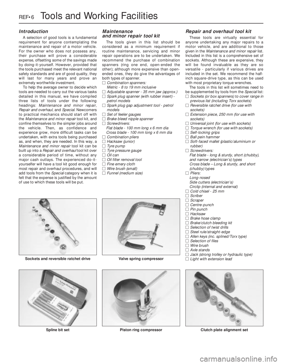
Sockets and reversible ratchet drive
Clutch plate alignment setPiston ring compressorSpline bit set
Valve spring compressor
Page 248 of 525
MOTTest Checks REF•9
Seat belts and seats
Note: The following checks are applicable to
all seat belts, front and rear.
MExamine the webbing of all the belts
(including rear belts if fitted) for cuts, serious
fraying or deterioration. Fasten and unfasten
each belt to check the buckles. If applicable,
check the retracting mechanism. Check the
security of all seat belt mountings accessible
from inside the vehicle.
MThe front seats themselves must be
securely attached and the backrests must
lock in the upright position.
Doors
MBoth front doors must be able to be opened
and closed from outside and inside, and must
latch securely when closed.
Vehicle identification
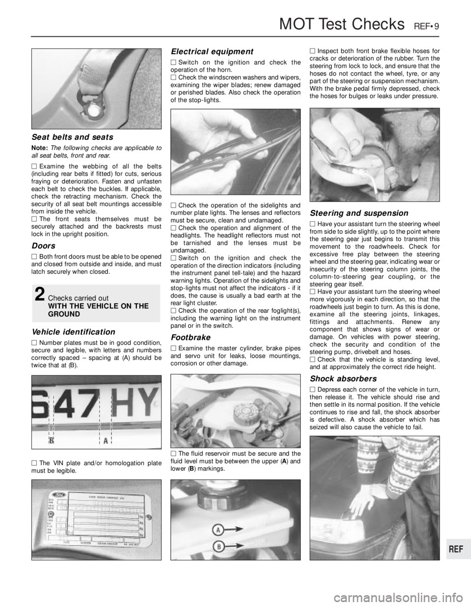
MNumber plates must be in good condition,
secure and legible, with letters and numbers
correctly spaced – spacing at (A) should be
twice that at (B).
MThe VIN plate and/or homologation plate
must be legible.
Electrical equipment
MSwitch on the ignition and check the
operation of the horn.
MCheck the windscreen washers and wipers,
examining the wiper blades; renew damaged
or perished blades. Also check the operation
of the stop-lights.
MCheck the operation of the sidelights and
number plate lights. The lenses and reflectors
must be secure, clean and undamaged.
MCheck the operation and alignment of the
headlights. The headlight reflectors must not
be tarnished and the lenses must be
undamaged.
MSwitch on the ignition and check the
operation of the direction indicators (including
the instrument panel tell-tale) and the hazard
warning lights. Operation of the sidelights and
stop-lights must not affect the indicators - if it
does, the cause is usually a bad earth at the
rear light cluster.
MCheck the operation of the rear foglight(s),
including the warning light on the instrument
panel or in the switch.
Footbrake
MExamine the master cylinder, brake pipes
and servo unit for leaks, loose mountings,
corrosion or other damage.
MThe fluid reservoir must be secure and the
fluid level must be between the upper (A) and
lower (B) markings.MInspect both front brake flexible hoses for
cracks or deterioration of the rubber. Turn the
steering from lock to lock, and ensure that the
hoses do not contact the wheel, tyre, or any
part of the steering or suspension mechanism.
With the brake pedal firmly depressed, check
the hoses for bulges or leaks under pressure.
Steering and suspension
MHave your assistant turn the steering wheel
from side to side slightly, up to the point where
the steering gear just begins to transmit this
movement to the roadwheels. Check for
excessive free play between the steering
wheel and the steering gear, indicating wear or
insecurity of the steering column joints, the
column-to-steering gear coupling, or the
steering gear itself.
MHave your assistant turn the steering wheel
more vigorously in each direction, so that the
roadwheels just begin to turn. As this is done,
examine all the steering joints, linkages,
fittings and attachments. Renew any
component that shows signs of wear or
damage. On vehicles with power steering,
check the security and condition of the
steering pump, drivebelt and hoses.
MCheck that the vehicle is standing level,
and at approximately the correct ride height.
Shock absorbers
MDepress each corner of the vehicle in turn,
then release it. The vehicle should rise and
then settle in its normal position. If the vehicle
continues to rise and fall, the shock absorber
is defective. A shock absorber which has
seized will also cause the vehicle to fail.
2Checks carried out
WITH THE VEHICLE ON THE
GROUND
REF
Page 249 of 525
REF•10MOTTest Checks
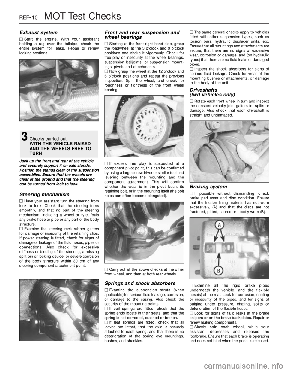
Exhaust system
MStart the engine. With your assistant
holding a rag over the tailpipe, check the
entire system for leaks. Repair or renew
leaking sections.
Jack up the front and rear of the vehicle,
and securely support it on axle stands.
Position the stands clear of the suspension
assemblies. Ensure that the wheels are
clear of the ground and that the steering
can be turned from lock to lock.
Steering mechanism
MHave your assistant turn the steering from
lock to lock. Check that the steering turns
smoothly, and that no part of the steering
mechanism, including a wheel or tyre, fouls
any brake hose or pipe or any part of the body
structure.
MExamine the steering rack rubber gaiters
for damage or insecurity of the retaining clips.
If power steering is fitted, check for signs of
damage or leakage of the fluid hoses, pipes or
connections. Also check for excessive
stiffness or binding of the steering, a missing
split pin or locking device, or severe corrosion
of the body structure within 30 cm of any
steering component attachment point.
Front and rear suspension and
wheel bearings
MStarting at the front right-hand side, grasp
the roadwheel at the 3 o’clock and 9 o’clock
positions and shake it vigorously. Check for
free play or insecurity at the wheel bearings,
suspension balljoints, or suspension mount-
ings, pivots and attachments.
MNow grasp the wheel at the 12 o’clock and
6 o’clock positions and repeat the previous
inspection. Spin the wheel, and check for
roughness or tightness of the front wheel
bearing.
MIf excess free play is suspected at a
component pivot point, this can be confirmed
by using a large screwdriver or similar tool and
levering between the mounting and the
component attachment. This will confirm
whether the wear is in the pivot bush, its
retaining bolt, or in the mounting itself (the bolt
holes can often become elongated).
MCarry out all the above checks at the other
front wheel, and then at both rear wheels.
Springs and shock absorbers
MExamine the suspension struts (when
applicable) for serious fluid leakage, corrosion,
or damage to the casing. Also check the
security of the mounting points.
MIf coil springs are fitted, check that the
spring ends locate in their seats, and that the
spring is not corroded, cracked or broken.
MIf leaf springs are fitted, check that all
leaves are intact, that the axle is securely
attached to each spring, and that there is no
deterioration of the spring eye mountings,
bushes, and shackles.MThe same general checks apply to vehicles
fitted with other suspension types, such as
torsion bars, hydraulic displacer units, etc.
Ensure that all mountings and attachments are
secure, that there are no signs of excessive
wear, corrosion or damage, and (on hydraulic
types) that there are no fluid leaks or damaged
pipes.
MInspect the shock absorbers for signs of
serious fluid leakage. Check for wear of the
mounting bushes or attachments, or damage
to the body of the unit.
Driveshafts
(fwd vehicles only)
MRotate each front wheel in turn and inspect
the constant velocity joint gaiters for splits or
damage. Also check that each driveshaft is
straight and undamaged.
Braking system
MIf possible without dismantling, check
brake pad wear and disc condition. Ensure
that the friction lining material has not worn
excessively, (A) and that the discs are not
fractured, pitted, scored or badly worn (B).
MExamine all the rigid brake pipes
underneath the vehicle, and the flexible
hose(s) at the rear. Look for corrosion, chafing
or insecurity of the pipes, and for signs of
bulging under pressure, chafing, splits or
deterioration of the flexible hoses.
MLook for signs of fluid leaks at the brake
calipers or on the brake backplates. Repair or
renew leaking components.
MSlowly spin each wheel, while your
assistant depresses and releases the
footbrake. Ensure that each brake is operating
and does not bind when the pedal is released.
3Checks carried out
WITH THE VEHICLE RAISED
AND THE WHEELS FREE TO
TURN
Page 250 of 525
MOTTest Checks REF•11
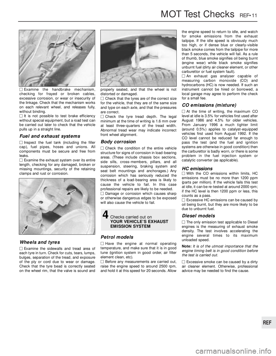
MExamine the handbrake mechanism,
checking for frayed or broken cables,
excessive corrosion, or wear or insecurity of
the linkage. Check that the mechanism works
on each relevant wheel, and releases fully,
without binding.
MIt is not possible to test brake efficiency
without special equipment, but a road test can
be carried out later to check that the vehicle
pulls up in a straight line.
Fuel and exhaust systems
MInspect the fuel tank (including the filler
cap), fuel pipes, hoses and unions. All
components must be secure and free from
leaks.
MExamine the exhaust system over its entire
length, checking for any damaged, broken or
missing mountings, security of the retaining
clamps and rust or corrosion.
Wheels and tyres
MExamine the sidewalls and tread area of
each tyre in turn. Check for cuts, tears, lumps,
bulges, separation of the tread, and exposure
of the ply or cord due to wear or damage.
Check that the tyre bead is correctly seated
on the wheel rim, that the valve is sound andproperly seated, and that the wheel is not
distorted or damaged.
MCheck that the tyres are of the correct size
for the vehicle, that they are of the same size
and type on each axle, and that the pressures
are correct.
MCheck the tyre tread depth. The legal
minimum at the time of writing is 1.6 mm over
at least three-quarters of the tread width.
Abnormal tread wear may indicate incorrect
front wheel alignment.
Body corrosion
MCheck the condition of the entire vehicle
structure for signs of corrosion in load-bearing
areas. (These include chassis box sections,
side sills, cross-members, pillars, and all
suspension, steering, braking system and
seat belt mountings and anchorages.) Any
corrosion which has seriously reduced the
thickness of a load-bearing area is likely to
cause the vehicle to fail. In this case
professional repairs are likely to be needed.
MDamage or corrosion which causes sharp
or otherwise dangerous edges to be exposed
will also cause the vehicle to fail.
Petrol models
MHave the engine at normal operating
temperature, and make sure that it is in good
tune (ignition system in good order, air filter
element clean, etc).
MBefore any measurements are carried out,
raise the engine speed to around 2500 rpm,
and hold it at this speed for 20 seconds. Allowthe engine speed to return to idle, and watch
for smoke emissions from the exhaust
tailpipe. If the idle speed is obviously much
too high, or if dense blue or clearly-visible
black smoke comes from the tailpipe for more
than 5 seconds, the vehicle will fail. As a rule
of thumb, blue smoke signifies oil being burnt
(engine wear) while black smoke signifies
unburnt fuel (dirty air cleaner element, or other
carburettor or fuel system fault).
MAn exhaust gas analyser capable of
measuring carbon monoxide (CO) and
hydrocarbons (HC) is now needed. If such an
instrument cannot be hired or borrowed, a
local garage may agree to perform the check
for a small fee.
CO emissions (mixture)
MAt the time of writing, the maximum CO
level at idle is 3.5% for vehicles first used after
August 1986 and 4.5% for older vehicles.
From January 1996 a much tighter limit
(around 0.5%) applies to catalyst-equipped
vehicles first used from August 1992. If the
CO level cannot be reduced far enough to
pass the test (and the fuel and ignition
systems are otherwise in good condition) then
the carburettor is badly worn, or there is some
problem in the fuel injection system or
catalytic converter (as applicable).
HC emissionsMWith the CO emissions within limits, HC
emissions must be no more than 1200 ppm
(parts per million). If the vehicle fails this test
at idle, it can be re-tested at around 2000 rpm;
if the HC level is then 1200 ppm or less, this
counts as a pass.
MExcessive HC emissions can be caused by
oil being burnt, but they are more likely to be
due to unburnt fuel.
Diesel models
MThe only emission test applicable to Diesel
engines is the measuring of exhaust smoke
density. The test involves accelerating the
engine several times to its maximum
unloaded speed.
Note: It is of the utmost importance that the
engine timing belt is in good condition before
the test is carried out.
M
Excessive smoke can be caused by a dirty
air cleaner element. Otherwise, professional
advice may be needed to find the cause.
4Checks carried out on
YOUR VEHICLE’S EXHAUST
EMISSION SYSTEM
REF
Page 251 of 525
Engine
m mEngine fails to rotate when attempting to start
m mEngine rotates, but will not start
m mEngine difficult to start when cold
m mEngine difficult to start when hot
m mStarter motor noisy or excessively rough in engagement
m mEngine starts, but stops immediately
m mEngine idles erratically
m mEngine misfires at idle speed
m mEngine misfires throughout the driving speed range
m mEngine hesitates on acceleration
m mEngine stalls
m mEngine lacks power
m mEngine backfires
m mOil pressure warning light illuminated with engine running
m mEngine runs-on after switching off
m mEngine noises
Cooling system
m
mOverheating
m mOvercooling
m mExternal coolant leakage
m mInternal coolant leakage
m mCorrosion
Fuel and exhaust systems
m
mExcessive fuel consumption
m mFuel leakage and/or fuel odour
m mExcessive noise or fumes from exhaust system
Clutch
m
mPedal travels to floor - no pressure or very little resistance
m mClutch fails to disengage (unable to select gears)
m mClutch slips (engine speed increases, with no increase in vehicle
speed)
m mJudder as clutch is engaged
m mNoise when depressing or releasing clutch pedal
Manual transmission
m
mNoisy in neutral with engine running
m mNoisy in one particular gear
m mDifficulty engaging gears
m mJumps out of gear
m mVibration
m mLubricant leaks
Automatic transmission
m
mFluid leakage
m mTransmission fluid brown, or has burned smell
m mGeneral gear selection problems
m mTransmission will not downshift (kickdown) with accelerator fully
depressed
m mEngine will not start in any gear, or starts in gears other than Park
or Neutral
m mTransmission slips, shifts roughly, is noisy, or has no drive in
forward or reverse gears
Driveshafts
m mClicking or knocking noise on turns (at slow speed on full-lock)
m mVibration when accelerating or decelerating
Braking system
m
mVehicle pulls to one side under braking
m mNoise (grinding or high-pitched squeal) when brakes applied
m mExcessive brake pedal travel
m mBrake pedal feels spongy when depressed
m mExcessive brake pedal effort required to stop vehicle
m mJudder felt through brake pedal or steering wheel when braking
m mBrakes binding
m mRear wheels locking under normal braking
Suspension and steering systems
m
mVehicle pulls to one side
m mWheel wobble and vibration
m mExcessive pitching and/or rolling around corners, or during
braking
m mWandering or general instability
m mExcessively stiff steering
m mExcessive play in steering
m mLack of power assistance
m mTyre wear excessive
Electrical system
m
mBattery will not hold a charge for more than a few days
m mIgnition/no-charge warning light remains illuminated with engine
running
m mIgnition/no-charge warning light fails to come on
m mLights inoperative
m mInstrument readings inaccurate or erratic
m mHorn inoperative, or unsatisfactory in operation
m mWindscreen/tailgate wipers inoperative, or unsatisfactory in
operation
m mWindscreen/tailgate washers inoperative, or unsatisfactory in
operation
m mElectric windows inoperative, or unsatisfactory in operation
m mCentral locking system inoperative, or unsatisfactory in operation
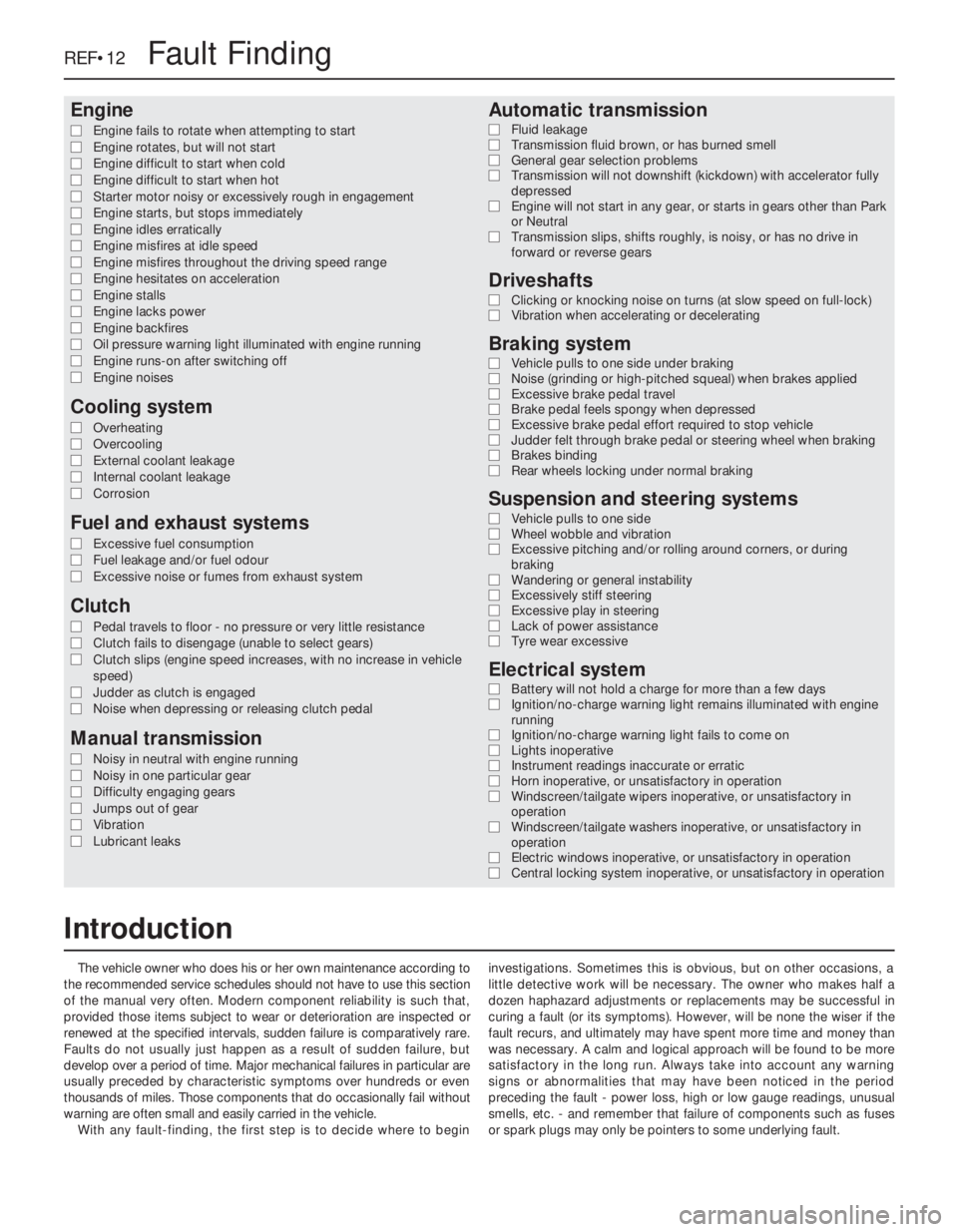
The vehicle owner who does his or her own maintenance according to
the recommended service schedules should not have to use this section
of the manual very often. Modern component reliability is such that,
provided those items subject to wear or deterioration are inspected or
renewed at the specified intervals, sudden failure is comparatively rare.
Faults do not usually just happen as a result of sudden failure, but
develop over a period of time. Major mechanical failures in particular are
usually preceded by characteristic symptoms over hundreds or even
thousands of miles. Those components that do occasionally fail without
warning are often small and easily carried in the vehicle.
With any fault-finding, the first step is to decide where to begininvestigations. Sometimes this is obvious, but on other occasions, a
little detective work will be necessary. The owner who makes half a
dozen haphazard adjustments or replacements may be successful in
curing a fault (or its symptoms). However, will be none the wiser if the
fault recurs, and ultimately may have spent more time and money than
was necessary. A calm and logical approach will be found to be more
satisfactory in the long run. Always take into account any warning
signs or abnormalities that may have been noticed in the period
preceding the fault - power loss, high or low gauge readings, unusual
smells, etc. - and remember that failure of components such as fuses
or spark plugs may only be pointers to some underlying fault.
REF•12Fault Finding
Introduction
Page 254 of 525
Excessive fuel consumption
MAir filter element dirty or clogged (Chapter 1).
MChoke cable incorrectly adjusted, or choke sticking - carburettor
models (Chapter 4A).
MFuel injection system fault - fuel-injected models (Chapter 4B).
MIgnition timing incorrect/ignition system fault (Chapters 1 and 5).
MTyres under-inflated (Chapter 1).
Fuel leakage and/or fuel odour
MDamaged or corroded fuel tank, pipes or connections (Chapter 4A
or 4B).
MCarburettor float chamber flooding (float height incorrect) -
carburettor models (Chapter 4A).
Excessive noise or fumes from exhaust system
MLeaking exhaust system or manifold joints (Chapters 1 and 4C).
MLeaking, corroded or damaged silencers or pipe (Chapters 1 and 4C).
MBroken mountings causing body or suspension contact (Chapter 1).
Pedal travels to floor - no pressure or very little
resistance
MBroken clutch cable (Chapter 6).
MIncorrect clutch cable adjustment (Chapter 6).
MBroken clutch release bearing or fork (Chapter 6).
MBroken diaphragm spring in clutch pressure plate (Chapter 6).
Clutch fails to disengage (unable to select gears).
MIncorrect clutch cable adjustment (Chapter 6).
MClutch disc sticking on transmission input shaft splines (Chapter 6).
MClutch disc sticking to flywheel or pressure plate (Chapter 6).
MFaulty pressure plate assembly (Chapter 6).
MClutch release mechanism worn or incorrectly assembled (Chapter 6).
Clutch slips (engine speed increases, with no
increase in vehicle speed).
MIncorrect clutch cable adjustment (Chapter 6).
MClutch disc linings excessively worn (Chapter 6).MClutch disc linings contaminated with oil or grease (Chapter 6).
MFaulty pressure plate or weak diaphragm spring (Chapter 6).
Judder as clutch is engaged
MClutch disc linings contaminated with oil or grease (Chapter 6).
MClutch disc linings excessively worn (Chapter 6).
MClutch cable sticking or frayed (Chapter 6).
MFaulty or distorted pressure plate or diaphragm spring (Chapter 6).
MWorn or loose engine or transmission mountings (Chapter 2A or 2B).
MClutch disc hub or transmission input shaft splines worn (Chapter 6).
Noise when depressing or releasing clutch pedal
MWorn clutch release bearing (Chapter 6).
MWorn or dry clutch pedal bushes (Chapter 6).
MFaulty pressure plate assembly (Chapter 6).
MPressure plate diaphragm spring broken (Chapter 6).
MBroken clutch disc cushioning springs (Chapter 6).
Fault Finding REF•15
REF
Overheating
MInsufficient coolant in system (Chapter 1).
MThermostat faulty (Chapter 3).
MRadiator core blocked, or grille restricted (Chapter 3).
MElectric cooling fan or thermoswitch faulty (Chapter 3).
MPressure cap faulty (Chapter 3).
MIgnition timing incorrect/ignition system fault (Chapters 1 and 5).
MInaccurate temperature gauge sender unit (Chapter 3).
MAirlock in cooling system (Chapter 1).
Overcooling
MThermostat faulty (Chapter 3).
MInaccurate temperature gauge sender unit (Chapter 3).
External coolant leakage
MDeteriorated or damaged hoses or hose clips (Chapter 1).
MRadiator core or heater matrix leaking (Chapter 3).
MPressure cap faulty (Chapter 3).
MWater pump seal leaking (Chapter 3).
MBoiling due to overheating (Chapter 3).
MCore plug leaking (Chapter 2A).
Internal coolant leakage
MLeaking cylinder head gasket (Chapter 2A or 2B).
MCracked cylinder head or cylinder bore (Chapter 2A or 2B).
Corrosion
MInfrequent draining and flushing (Chapter 1).
MIncorrect coolant mixture or inappropriate coolant type (Chapter 1).
Cooling system
Clutch
Fuel and exhaust systems
Page 256 of 525
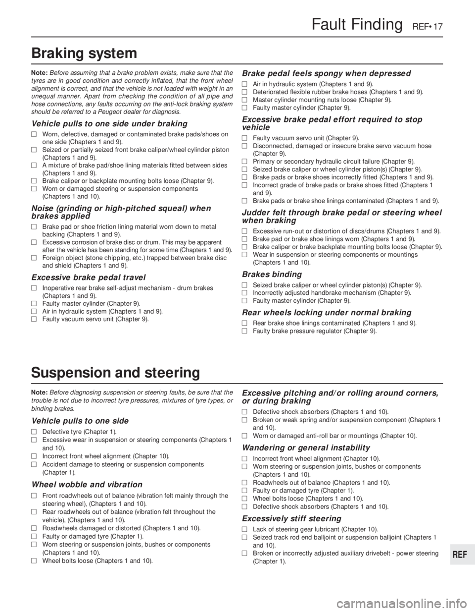
Note:Before diagnosing suspension or steering faults, be sure that the
trouble is not due to incorrect tyre pressures, mixtures of tyre types, or
binding brakes.
Vehicle pulls to one side
MDefective tyre (Chapter 1).
MExcessive wear in suspension or steering components (Chapters 1
and 10).
MIncorrect front wheel alignment (Chapter 10).
MAccident damage to steering or suspension components
(Chapter 1).
Wheel wobble and vibration
MFront roadwheels out of balance (vibration felt mainly through the
steering wheel), (Chapters 1 and 10).
MRear roadwheels out of balance (vibration felt throughout the
vehicle), (Chapters 1 and 10).
MRoadwheels damaged or distorted (Chapters 1 and 10).
MFaulty or damaged tyre (Chapter 1).
MWorn steering or suspension joints, bushes or components
(Chapters 1 and 10).
MWheel bolts loose (Chapters 1 and 10).
Excessive pitching and/or rolling around corners,
or during braking
MDefective shock absorbers (Chapters 1 and 10).
MBroken or weak spring and/or suspension component (Chapters 1
and 10).
MWorn or damaged anti-roll bar or mountings (Chapter 10).
Wandering or general instability
MIncorrect front wheel alignment (Chapter 10).
MWorn steering or suspension joints, bushes or components
(Chapters 1 and 10).
MRoadwheels out of balance (Chapters 1 and 10).
MFaulty or damaged tyre (Chapter 1).
MWheel bolts loose (Chapters 1 and 10).
MDefective shock absorbers (Chapters 1 and 10).
Excessively stiff steering
MLack of steering gear lubricant (Chapter 10).
MSeized track rod end balljoint or suspension balljoint (Chapters 1
and 10).
MBroken or incorrectly adjusted auxiliary drivebelt - power steering
(Chapter 1).
Fault Finding REF•17
REF
Note:Before assuming that a brake problem exists, make sure that the
tyres are in good condition and correctly inflated, that the front wheel
alignment is correct, and that the vehicle is not loaded with weight in an
unequal manner. Apart from checking the condition of all pipe and
hose connections, any faults occurring on the anti-lock braking system
should be referred to a Peugeot dealer for diagnosis.
Vehicle pulls to one side under braking
MWorn, defective, damaged or contaminated brake pads/shoes on
one side (Chapters 1 and 9).
MSeized or partially seized front brake caliper/wheel cylinder piston
(Chapters 1 and 9).
MA mixture of brake pad/shoe lining materials fitted between sides
(Chapters 1 and 9).
MBrake caliper or backplate mounting bolts loose (Chapter 9).
MWorn or damaged steering or suspension components
(Chapters 1 and 10).
Noise (grinding or high-pitched squeal) when
brakes applied
MBrake pad or shoe friction lining material worn down to metal
backing (Chapters 1 and 9).
MExcessive corrosion of brake disc or drum. This may be apparent
after the vehicle has been standing for some time (Chapters 1 and 9).
MForeign object (stone chipping, etc.) trapped between brake disc
and shield (Chapters 1 and 9).
Excessive brake pedal travel
MInoperative rear brake self-adjust mechanism - drum brakes
(Chapters 1 and 9).
MFaulty master cylinder (Chapter 9).
MAir in hydraulic system (Chapters 1 and 9).
MFaulty vacuum servo unit (Chapter 9).
Brake pedal feels spongy when depressed
MAir in hydraulic system (Chapters 1 and 9).
MDeteriorated flexible rubber brake hoses (Chapters 1 and 9).
MMaster cylinder mounting nuts loose (Chapter 9).
MFaulty master cylinder (Chapter 9).
Excessive brake pedal effort required to stop
vehicle
MFaulty vacuum servo unit (Chapter 9).
MDisconnected, damaged or insecure brake servo vacuum hose
(Chapter 9).
MPrimary or secondary hydraulic circuit failure (Chapter 9).
MSeized brake caliper or wheel cylinder piston(s) (Chapter 9).
MBrake pads or brake shoes incorrectly fitted (Chapters 1 and 9).
MIncorrect grade of brake pads or brake shoes fitted (Chapters 1
and 9).
MBrake pads or brake shoe linings contaminated (Chapters 1 and 9).
Judder felt through brake pedal or steering wheel
when braking
MExcessive run-out or distortion of discs/drums (Chapters 1 and 9).
MBrake pad or brake shoe linings worn (Chapters 1 and 9).
MBrake caliper or brake backplate mounting bolts loose (Chapter 9).
MWear in suspension or steering components or mountings
(Chapters 1 and 10).
Brakes binding
MSeized brake caliper or wheel cylinder piston(s) (Chapter 9).
MIncorrectly adjusted handbrake mechanism (Chapter 9).
MFaulty master cylinder (Chapter 9).
Rear wheels locking under normal braking
MRear brake shoe linings contaminated (Chapters 1 and 9).
MFaulty brake pressure regulator (Chapter 9).
Braking system
Suspension and steering
Page 266 of 525
Pierburg 2E3 carburettor- 4A•5
Piston rings- 2A•30
Piston/connecting rod- 2A•29
Plastic components- 11•3
Potentiometer- 4B•12, 4B•16
Power steering fluid - 0•14, 0•17, 1•2, 1•12
Power steering pump- 10•22
Power steering system bleeding- 10•22
Punctures- 0•8
RRadiator- 3•3
Radiator cooling fan- 3•5
Radiator grille- 11•12
Radio/cassette anti theft system- REF•5
Radio/cassette player- 12•18
Rear hub- 10•10, 10•15
Rear lamps- 12•11
Rear suspension assembly- 10•15
Relays- 12•3
Release bearing (clutch)- 6•6
Repair procedures- REF •4
Respraying- 11•2
Reversing lamp switch- 7A•6
Road test- 1•13
Roll bars- 10•8, 10•13, 10•17
Routine maintenance - 1•1 et seq
SSafety first!- 0•5
Scratches- 11•2
Seat belts- 11•21
Seats- 11•20, 11•22
Seats heated- 12•6
Selector cable (automatics)- 7B•4
Selector lever- 7B•4
Sender unit fuel level- 4A•4, 4B•8
Sender units (temperature gauge)- 3•6
Servicing - see Routine maintenance
Servo unit (braking system)- 9•15
Shock absorber- 10•11
Shoes (brake)- 9•6
Short-circuit finding- 12•2
Spark plugs- 1•3, 1•14, 1•16
Speakers- 12•17
Speedometer cable- 12•18
Speedometer drive- 7A•6
Starter inhibitor switch- 7B•3
Starter motor- 5•8
Starting problems- 0•6
Steering wheel alignment- 10•1, 10•24
Steering- 10•1 et seq
camber - 10•1 10•24
castor - 10•1, 10•24
column - 10•18
damper - 10•21
fault diagnosis - REF•12, REF•17gear - 10•21
power steering system bleeding - 10•22
power steering fluid - 0•17, 1•2
power steering pump - 10•22
shaft rubber coupling - 10•18
tie-rod end - 10•23
toe setting - 10•1, 10•24
wheel - 10•17
wheel bearing - 10•4, 10•9, 10•14
wheel with airbag - 12•20
Stub axle- 10•13
Subframe- 10•5
Sump- 2A•27, 2B•9
Sunroof- 11•13
Sunroof motor- 12•18
Sunroof switch- 12•5
Suspension- 10•1 et seq
anti-roll bars - 10•8, 10•13, 10•17
assembly (rear) - 10•15
coil spring (rear) - 10•12, 10•15
fault diagnosis - REF•12, REF•17
level control system - 10•14
lower arm (front) - 10•7
rear hub - 10•10, 10•15
shock absorber - 10•11
strut (front) - 10•6
stub axle - 10•13
sub frame - 10•5
trailing arms - 10•12, 10•16
wheel bearing - 10•4, 10•9, 10•14
Suspension/steering checks- 1•10
Switches:
brake lamp - 12•5
cooling fan - 3•6
courtesy lamp - 12•5
electric door mirror - 12•5
handbrake warning lamp - 12•5
hazard warning - 12•4
heater blower motor - 12•4
ignition - 12•3
indicator - 12•4
kickdown - 7B•3
lights - 12•4
luggage compartment - 12•5
oil pressure warning lamp - 12•5
push button - 12•4
reversing lamp - 7A•6
starter inhibitor - 7B•3
sunroof - 12•5
TTailgate- 11•5
Temperature gauge sender- 3•6
Temperature sensor (automatics)- 7B•5
Thermostat- 3•4
Throttle cable- 4A•5, 4B•9
Throttle pedal- 4A•5Tie-rod end- 10•23
Timing- 5•2, 5•13
Timing belt- 1•16, 2A•13, 2B•3, 2B•6
Toe setting- 10•1, 10•24
Tools and working facilities- REF•4, REF•6,
REF•7
Towing- 0•9
Trim panel (door)- 11•6
Tyre checks- 0•16, 0•17
Tyre pressures- 0•17
UUnderbody- 11•1
Underbody views- 1•7
Underbonnet views- 0•10, 1•5
Upholstery and carpets- 11•2
VVacuum servo unit (braking system)- 9•15
Valve lifters- 2A•24, 2B•9
Valves- 2A•5, 2B•2
Vehicle identification numbers- REF•3
Ventilation system- 3•1 et seq
Vents- 3•8
WWasher fluid- 0•13, 1•2
Washers- 12•13, 12•15
Water pump- 3•4
Weekly checks- 0•10et seq
Wheelalignment- 10•1, 10•24
Wheel arch liners- 11•12
Wheel bearing- 10•4, 10•9, 10•14
Wheel changing- 0•8
Wheel cylinder- 9•11
Window glass- 11•9
Window regulator- 11•10
Windscreen- 11•9, 11•12
Wiper blades- 0•15, 12•13
Wiper motors- 12•14
Wiring diagrams- 12•22 et seq
Index REF•27
REF