PEUGEOT 206 CC DAG 2001 Owners Manual
Manufacturer: PEUGEOT, Model Year: 2001, Model line: 206 CC DAG, Model: PEUGEOT 206 CC DAG 2001Pages: 123, PDF Size: 2.86 MB
Page 101 of 123
PRACTICAL ASPECTS OF YOUR VEHICLE99
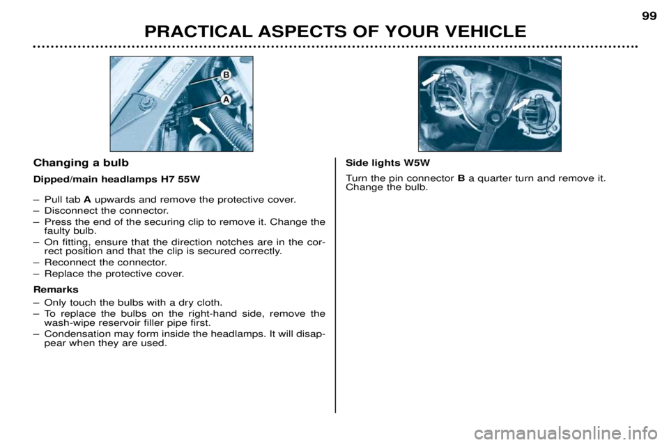
Ð Pull tab
Aupwards and remove the protective cover.
Ð Disconnect the connector.
Ð Press the end of the securing clip to remove it. Change the faulty bulb.
Ð On fitting, ensure that the direction notches are in the cor- rect position and that the clip is secured correctly.
Ð Reconnect the connector.
Ð Replace the protective cover. Remarks
Ð Only touch the bulbs with a dry cloth.
Ð To replace the bulbs on the right-hand side, remove the wash-wipe reservoir filler pipe first.
Ð Condensation may form inside the headlamps. It will disap- pear when they are used.
Changing a bulb Dipped/main headlamps H7 55WSide lights W5W
Turn the pin connector Ba quarter turn and remove it.
Change the bulb.
Page 102 of 123
PRACTICAL ASPECTS OF YOUR VEHICLE
100
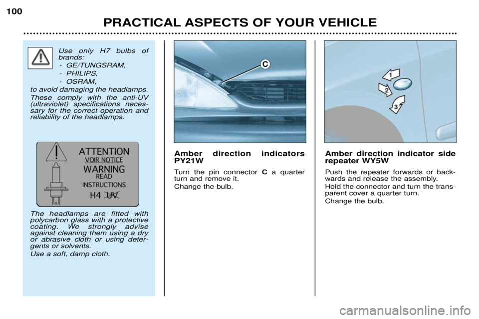
Amber direction indicators PY21W
Turn the pin connector
Ca quarter
turn and remove it. Change the bulb. Amber direction indicator side repeater WY5W Push the repeater forwards or back-
wards and release the assembly. Hold the connector and turn the trans- parent cover a quarter turn. Change the bulb.
Use only H7 bulbs of brands:
- GE/TUNGSRAM,
- PHILIPS,
- OSRAM,
to avoid damaging the headlamps.These comply with the anti-UV (ultraviolet) specifications neces-sary for the correct operation andreliability of the headlamps. The headlamps are fitted with polycarbon glass with a protective
coating. We strongly adviseagainst cleaning them using a dryor abrasive cloth or using deter-gents or solvents. Use a soft, damp cloth.
Page 103 of 123
PRACTICAL ASPECTS OF YOUR VEHICLE101
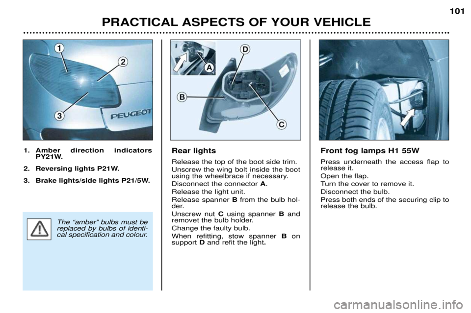
Rear lights Release the top of the boot side trim. Unscrew the wing bolt inside the boot
using the wheelbrace if necessary. Disconnect the connector
A.
Release the light unit.Release spanner B from the bulb hol-
der.Unscrew nut Cusing spanner B and
removet the bulb holder.Change the faulty bulb.When refitting, stow spanner B on
support D and refit the light .
1. Amber direction indicators
PY21W.
2. Reversing lights P21W.
3. Brake lights/side lights P21/5W.Front fog lamps H1 55W Press underneath the access flap to release it. Open the flap.
Turn the cover to remove it.Disconnect the bulb.Press both ends of the securing clip to release the bulb.
The ÒamberÓ bulbs must be replaced by bulbs of identi-
cal specification and colour.
Page 104 of 123
PRACTICAL ASPECTS OF YOUR VEHICLE101
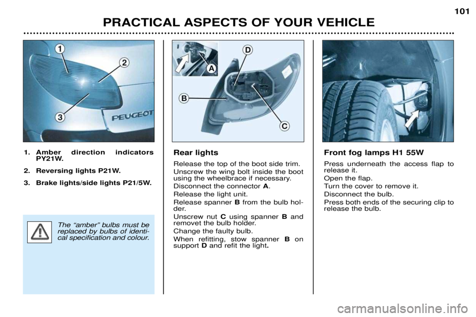
Rear lights Release the top of the boot side trim. Unscrew the wing bolt inside the boot
using the wheelbrace if necessary. Disconnect the connector
A.
Release the light unit.Release spanner B from the bulb hol-
der.Unscrew nut Cusing spanner B and
removet the bulb holder.Change the faulty bulb.When refitting, stow spanner B on
support D and refit the light .
1. Amber direction indicators
PY21W.
2. Reversing lights P21W.
3. Brake lights/side lights P21/5W.Front fog lamps H1 55W Press underneath the access flap to release it. Open the flap.
Turn the cover to remove it.Disconnect the bulb.Press both ends of the securing clip to release the bulb.
The ÒamberÓ bulbs must be replaced by bulbs of identi-
cal specification and colour.
Page 105 of 123
PRACTICAL ASPECTS OF YOUR VEHICLE
102
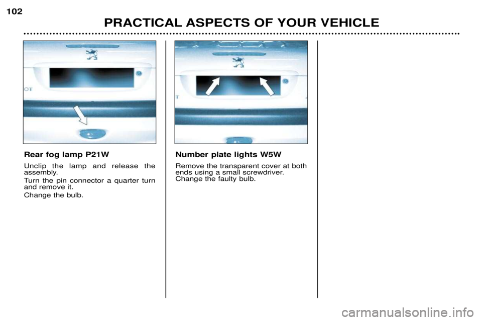
Rear fog lamp P21W Unclip the lamp and release the
assembly.
Turn the pin connector a quarter turn and remove it. Change the bulb. Number plate lights W5W Remove the transparent cover at both
ends using a small screwdriver.Change the faulty bulb.
Page 106 of 123
PRACTICAL ASPECTS OF YOUR VEHICLE103
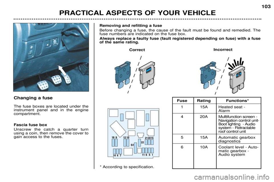
Changing a fuse
The fuse boxes are located under the instrument panel and in the enginecompartment. Fascia fuse box Unscrew the catch a quarter turn using a coin, then remove the cover togain access to the fuses.Removing and refitting a fuse
Before changing a fuse, the cause of the fault must be found and remedied. The fuse numbers are indicated on the fuse box. Always replace a faulty fuse (fault registered depending on fuse) with a fuse of the same rating.
Correct
Incorrect
* According to specification.Fuse Rating Functions*
1 15A Heated seat - Alarm
4 20A Mulltifunction screen - Navigation control unit-
Boot lighting - Audiosystem - Retractableroof control unit
5 15A Automatic gearbox diagnostics
6 10A Coolant level - Auto- matic gearbox - Audio system
Page 107 of 123
PRACTICAL ASPECTS OF YOUR VEHICLE103
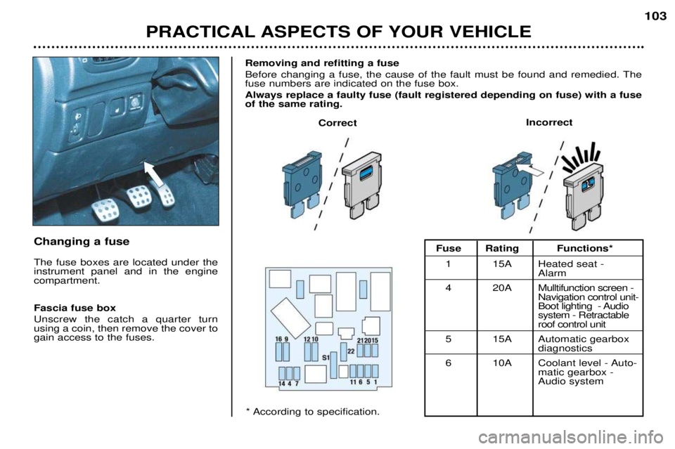
Changing a fuse
The fuse boxes are located under the instrument panel and in the enginecompartment. Fascia fuse box Unscrew the catch a quarter turn using a coin, then remove the cover togain access to the fuses.Removing and refitting a fuse
Before changing a fuse, the cause of the fault must be found and remedied. The fuse numbers are indicated on the fuse box. Always replace a faulty fuse (fault registered depending on fuse) with a fuse of the same rating.
Correct
Incorrect
* According to specification.Fuse Rating Functions*
1 15A Heated seat - Alarm
4 20A Mulltifunction screen - Navigation control unit-
Boot lighting - Audiosystem - Retractableroof control unit
5 15A Automatic gearbox diagnostics
6 10A Coolant level - Auto- matic gearbox - Audio system
Page 108 of 123
PRACTICAL ASPECTS OF YOUR VEHICLE
104
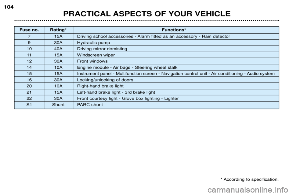
Fuse no. Rating*
Functions*
7 15A Driving school accessories - Alarm fitted as an accessory - Rain detector
9 30A Hydraulic pump
10 40A Driving mirror demisting 11 15A Windscreen wiper
12 30A Front windows
14 10A Engine module - Air bags - Steering wheel stalk
15 15A Instrument panel - Multifunction screen - Navigation control unit - Air conditioning - Audio system
16 30A Locking/unlocking of doors
20 10A Right-hand brake light
21 15A Left-hand brake light - 3rd brake light
22 30A Front courtesy light - Glove box lighting - Lighter
S1 Shunt PARC shunt
* According to specification.
Page 109 of 123
PRACTICAL ASPECTS OF YOUR VEHICLE105
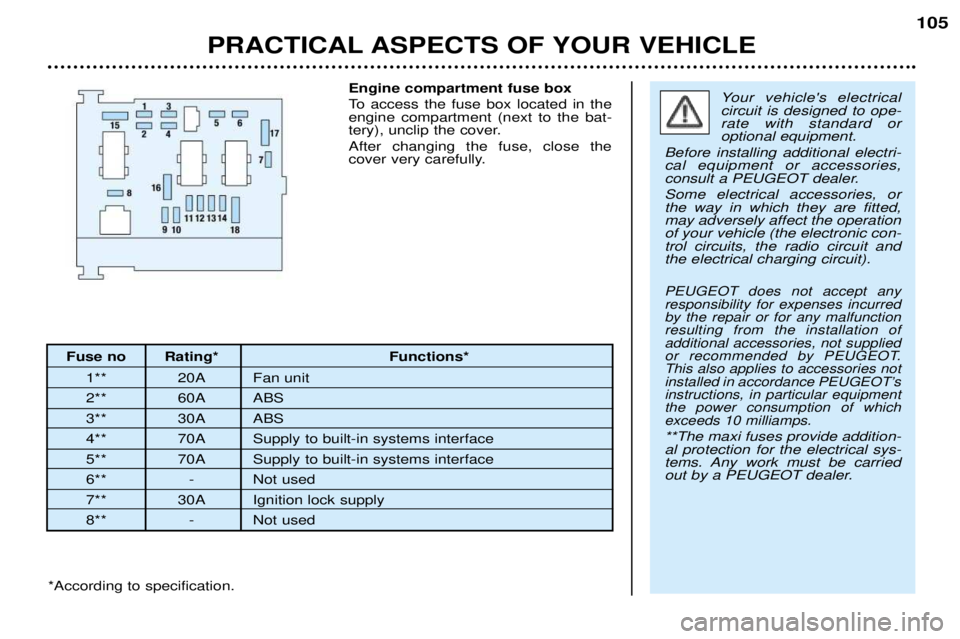
Fuse no Rating* Functions*
1** 20A Fan unit
2** 60A ABS
3** 30A ABS
4** 70A Supply to built-in systems interface
5** 70A Supply to built-in systems interface
6** - Not used
7** 30A Ignition lock supply
8** - Not used Engine compartment fuse box
To access the fuse box located in the engine compartment (next to the bat-
tery), unclip the cover. After changing the fuse, close the
cover very carefully.
Your vehicle's electrical circuit is designed to ope-rate with standard oroptional equipment.
Before installing additional electri-cal equipment or accessories,
consult a PEUGEOT dealer. Some electrical accessories, or the way in which they are fitted,may adversely affect the operationof your vehicle (the electronic con-trol circuits, the radio circuit andthe electrical charging circuit).
PEUGEOT does not accept anyresponsibility for expenses incurredby the repair or for any malfunctionresulting from the installation ofadditional accessories, not supplied
or recommended by PEUGEOT.This also applies to accessories not
installed in accordance PEUGEOTÕsinstructions, in particular equipmentthe power consumption of whichexceeds 10 milliamps.
**The maxi fuses provide addition-al protection for the electrical sys-
tems. Any work must be carried
out by a PEUGEOT dealer.
*According to specification.
Page 110 of 123
PRACTICAL ASPECTS OF YOUR VEHICLE
106
* According to specification
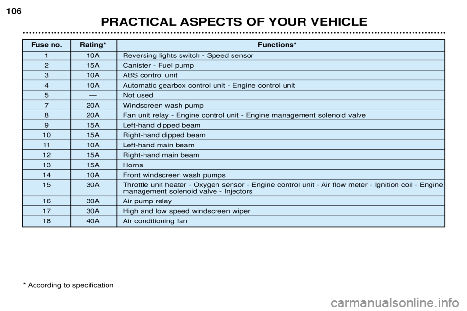
Fuse no. Rating*
Functions*
1 10A Reversing lights switch - Speed sensor
2 15A Canister - Fuel pump
3 10A ABS control unit
4 10A Automatic gearbox control unit - Engine control unit
5 Ñ Not used
7 20A Windscreen wash pump
8 20A Fan unit relay - Engine control unit - Engine management solenoid valve
9 15A Left-hand dipped beam
10 15A Right-hand dipped beam
11 10A Left-hand main beam
12 15A Right-hand main beam
13 15A Horns
14 10A Front windscreen wash pumps
15 30A Throttle unit heater - Oxygen sensor - Engine control unit - Air flow meter - Ignition coil - Engine
management solenoid valve - Injectors
16 30A Air pump relay
17 30A High and low speed windscreen wiper
18 40A Air conditioning fan