heater motor Peugeot 207 CC 2014 Owner's Manual
[x] Cancel search | Manufacturer: PEUGEOT, Model Year: 2014, Model line: 207 CC, Model: Peugeot 207 CC 2014Pages: 232, PDF Size: 11.11 MB
Page 147 of 232

9PRACTICAL INFORMATION
145
207CC_EN_CHAP09_INFO PRATIQUES_ED01-2014
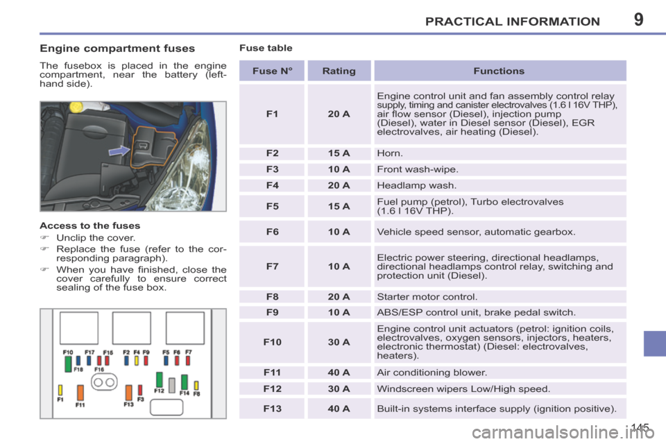
Engine compartment fuses
The fusebox is placed in the engine
compartment, near the battery (left-
hand side).
Access to the fuses
Unclip the cover.
Replace the fuse (refer to the cor-responding paragraph).
When you have fi nished, close the cover carefully to ensure correct
sealing of the fuse box. Fuse table
Fuse N° Rating Functions
F1 20 A Engine control unit and fan assembly control relay
supply, timing and canister electrovalves (1.6 l 16V THP),
air fl ow sensor (Diesel), injection pump
(Diesel), water in Diesel sensor (Diesel), EGR
electrovalves, air heating (Diesel).
F2 15 A Horn.
F3 10 A Front wash-wipe.
F4 20 A Headlamp wash.
F5 15 A Fuel pump (petrol), Turbo electrovalves
(1.6 l 16V THP).
F6 10 A Vehicle speed sensor, automatic gearbox.
F7 10 A Electric power steering, directional headlamps,
directional headlamps control relay, switching and
protection unit (Diesel).
F8 20 A Starter motor control.
F9 10 A ABS/ESP control unit, brake pedal switch.
F10 30 A Engine control unit actuators (petrol: ignition coils,
electrovalves, oxygen sensors, injectors, heaters,
electronic thermostat) (Diesel: electrovalves,
heaters).
F 11 40 A Air conditioning blower.
F12 30 A Windscreen wipers Low/High speed.
F13 40 A Built-in systems interface supply (ignition positive).
Page 148 of 232

9PRACTICAL INFORMATION
146
207CC_EN_CHAP09_INFO PRATIQUES_ED01-2014
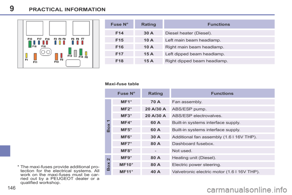
Fuse N° Rating Functions
F14 30 A Diesel heater (Diesel).
F15 10 A Left main beam headlamp.
F16 10 A Right main beam headlamp.
F17 15 A Left dipped beam headlamp.
F18 15 A Right dipped beam headlamp.
Maxi-fuse table
* The maxi-fuses provide additional pro- tection for the electrical systems. All
work on the maxi-fuses must be car-
ried out by a PEUGEOT dealer or a
qualifi ed workshop.
Fuse N° Rating Functions
Box 1
MF1 * 70 A Fan assembly.
MF2 * 20 A/30 A ABS/ESP pump.
MF3 * 20 A/30 A ABS/ESP electrovalves.
MF4 * 60 A Built-in systems interface supply.
MF5 * 60 A Built-in systems interface supply.
MF6 * 30 A Additional fan assembly (1.6 l 16V THP).
MF7 * 80 A Dashboard fusebox.
MF8 * - Not used.
Box 2
MF9 * 80 A Heating unit (Diesel).
MF10 * 80 A Electric power steering.
MF11 * 40 A Valvetronic electric motor (1.6 l 16V THP).