length PEUGEOT 3008 2021 Owners Manual
[x] Cancel search | Manufacturer: PEUGEOT, Model Year: 2021, Model line: 3008, Model: PEUGEOT 3008 2021Pages: 292, PDF Size: 9.65 MB
Page 44 of 292
42
Ease of use and comfort
Driving position
Correct seating position
Adopting a good driving position contributes to
improving driver comfort and protection.
It also optimises interior and exterior visibility as
well as access to controls.
Certain seat adjustments described in this
section depend on the trim level and the country
in which the vehicle is sold.
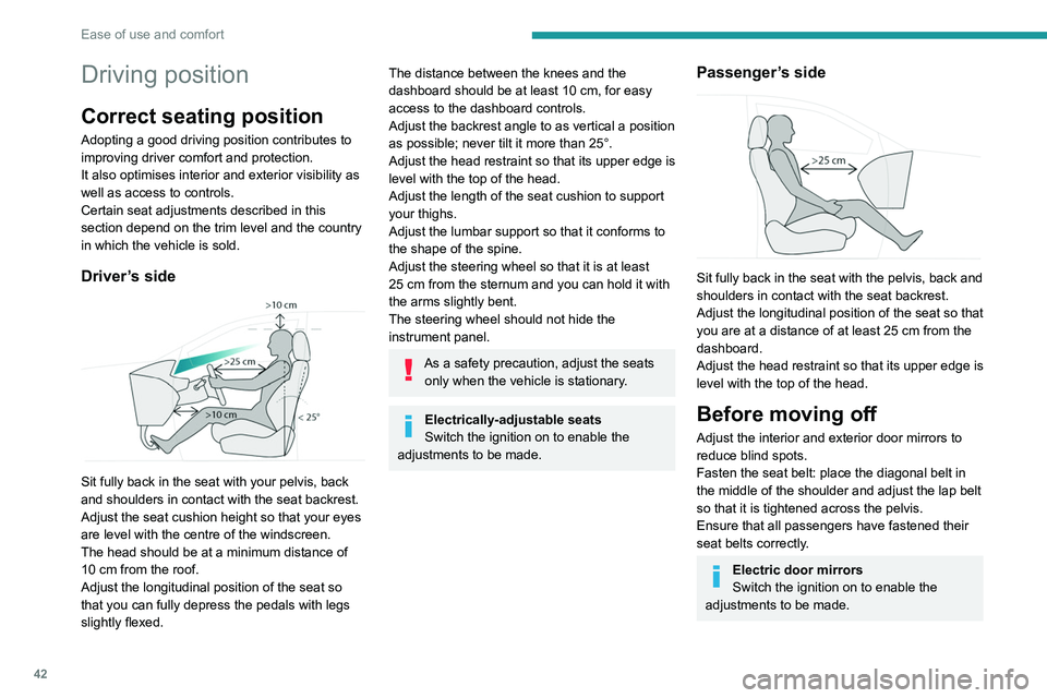
Driver’s side
Sit fully back in the seat with your pelvis, back
and shoulders in contact with the seat backrest.
Adjust the seat cushion height so that your eyes
are level with the centre of the windscreen.
The head should be at a minimum distance of
10 cm from the roof.
Adjust the longitudinal position of the seat so
that you can fully depress the pedals with legs
slightly flexed.
The distance between the knees and the
dashboard should be at least 10 cm, for easy
access to the dashboard controls.
Adjust the backrest angle to as vertical a position
as possible; never tilt it more than 25°.
Adjust the head restraint so that its upper edge is
level with the top of the head.
Adjust the length of the seat cushion to support
your thighs.
Adjust the lumbar support so that it conforms to
the shape of the spine.
Adjust the steering wheel so that it is at least
25
cm from the sternum and you can hold it with
the arms slightly bent.
The steering wheel should not hide the
instrument panel.
As a safety precaution, adjust the seats only when the vehicle is stationary.
Electrically-adjustable seats
Switch the ignition on to enable the
adjustments to be made.
Passenger’s side
Sit fully back in the seat with the pelvis, back and
shoulders in contact with the seat backrest.
Adjust the longitudinal position of the seat so that
you are at a distance of at least 25
cm from the
dashboard.
Adjust the head restraint so that its upper edge is
level with the top of the head.
Before moving off
Adjust the interior and exterior door mirrors to
reduce blind spots.
Fasten the seat belt: place the diagonal belt in
the middle of the shoulder and adjust the lap belt
so that it is tightened across the pelvis.
Ensure that all passengers have fastened their
seat belts correctly.
Electric door mirrors
Switch the ignition on to enable the
adjustments to be made.
When driving
Maintain a good driving position and hold the
steering wheel with both hands at the 'quarter to
three' position, so that you can easily and quickly
reach the controls behind and near the steering
wheel.
Never adjust the seats or steering wheel
when driving.
Always keep your feet on the floor.
Front seats
Before moving the seat backwards,
ensure that there is no person or object
that might prevent the full travel of the seat.
There is a risk of trapping or pinching
passengers if present in the rear seats or of
jamming the seat if large objects are placed
on the floor behind the seat.
Page 45 of 292
43
Ease of use and comfort
3When driving
Maintain a good driving position and hold the
steering wheel with both hands at the 'quarter to
three' position, so that you can easily and quickly
reach the controls behind and near the steering
wheel.
Never adjust the seats or steering wheel
when driving.
Always keep your feet on the floor.
Front seats
Before moving the seat backwards,
ensure that there is no person or object
that might prevent the full travel of the seat.
There is a risk of trapping or pinching
passengers if present in the rear seats or of
jamming the seat if large objects are placed
on the floor behind the seat.
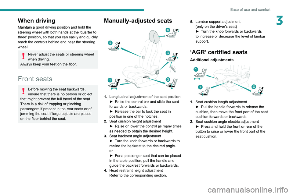
Manually-adjusted seats
1. Longitudinal adjustment of the seat position
►
Raise the control bar and slide the seat
forwards or backwards.
►
Release the bar to lock the seat in
position in one of the notches.
2. Seat cushion height adjustment
►
Raise or lower the control as many times
as needed to obtain the desired height.
3. Seat backrest angle adjustment
►
T
urn the knob forwards or backwards to
recline the backrest to the desired angle.
or
►
For a passenger seat that can be placed
in the table position, pull the handle and
guide the backrest forwards or backwards.
4. Head restraint height adjustment
Refer to the corresponding section. 5.
Lumbar support adjustment
(only on the driver's seat)
►
T
urn the knob forwards or backwards
to increase or decrease the level of lumbar
support.
‘AGR’ certified seats
Additional adjustments
1. Seat cushion length adjustment
►
Pull the handle forwards to release the
cushion, then move the front part of the seat
cushion forwards or backwards.
2. Seat cushion angle electric adjustment
►
Press and hold the front or rear of the
button to raise or lower the front part of the
seat cushion.
Page 47 of 292
45
Ease of use and comfort
3Refitting a head restraint
► Insert the head restraint rods into the guides
in the corresponding seat backrest.
►
Push the head restraint fully down.
►
Press the lug
A to release the head restraint
and push it down.
►
Adjust the height of the head restraint.
Never drive with the head restraints
removed; they should be in place and
adjusted for the occupant of the seat.
Electrically-adjusted driver's
seat
To carry out these electric adjustments, switch on the ignition or start the engine
if the vehicle has gone into energy economy
mode.
These electric adjustments are accessible
about 1 minute after opening the driver's door.
They are deactivated about 1 minute after
switching the ignition off.
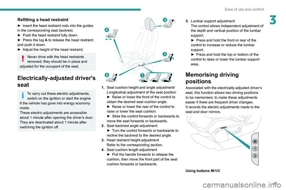
1. Seat cushion height and angle adjustment/
Longitudinal adjustment of the seat position
►
Raise or lower the front of the control to
obtain the desired seat cushion angle.
►
Raise or lower the rear of the control to
raise or lower the seat cushion.
►
Slide the control forwards or backwards to
move the seat forwards or backwards.
2. Seat backrest angle adjustment
►
T
urn the control forwards or backwards to
recline the backrest to the desired angle.
3. Head restraint height adjustment
Refer to the corresponding section.
4. Seat cushion length adjustment
►
Pull the handle forwards to release the
cushion, then move the front part of the seat
cushion forwards or backwards. 5.
Lumbar support adjustment
The control allows independent adjustment of
the depth and vertical position of the lumbar
support.
►
Press and hold the front or rear of the
control to increase or reduce the lumbar
support.
►
Press and hold the top or bottom of the
control to raise or lower the lumbar support
area.
Memorising driving
positions
Associated with the electrically-adjusted driver’s
seat, this function allows two driving positions
to be memorised, to make these adjustments
easier if there are frequent driver changes.
It records the electric adjustments made to the
seat and door mirrors.
Using buttons M/1/2
Page 83 of 292
81
Lighting and visibility
4Fast wiping (heavy rain)
Normal wiping (moderate rain)
Intermittent wiping (proportional to the
vehicle’s speed)
Switching off
Automatic wiping
Refer to the corresponding section.
Single wipe
► Pull the stalk briefly towards you.
In position 1 or 2, the wiping frequency is
automatically reduced when the speed of
the vehicle drops below 3
mph (5 km/h).
When the speed is above 6
mph (10 km/h)
again, the wiping frequency returns to the
original frequency (fast or normal).
Ha a gyújtást úgy vették le, hogy az
ablaktörlők jártak, működtesse újra a kart
a törlés ismételt bekapcsolásához, amint
visszakapcsolta a gyújtást (kivéve, ha a
gyújtás levétele egy percen belül történt).
After switching off the ignition, a slight movement of the windscreen wipers to
store them under the bonnet may occur.
Windscreen wash
► Pull the wiper control stalk towards you and
hold.
A
final wiping cycle is performed when
screenwashing ends.
The windscreen wash jets are incorporated into the tip of each wiper
arm.
Screenwash fluid is sprayed along the length
of the wiper blade. This improves visibility and
reduces screenwash fluid consumption.
To avoid damaging the wiper blades, do not operate the screenwash if the
screenwash reservoir is empty.
Only operate the screenwash if there is no
risk of the fluid freezing on the windscreen
and hindering visibility. During the winter
period, use "very cold climate" rated products.
Never top up with water.
Rear wiper
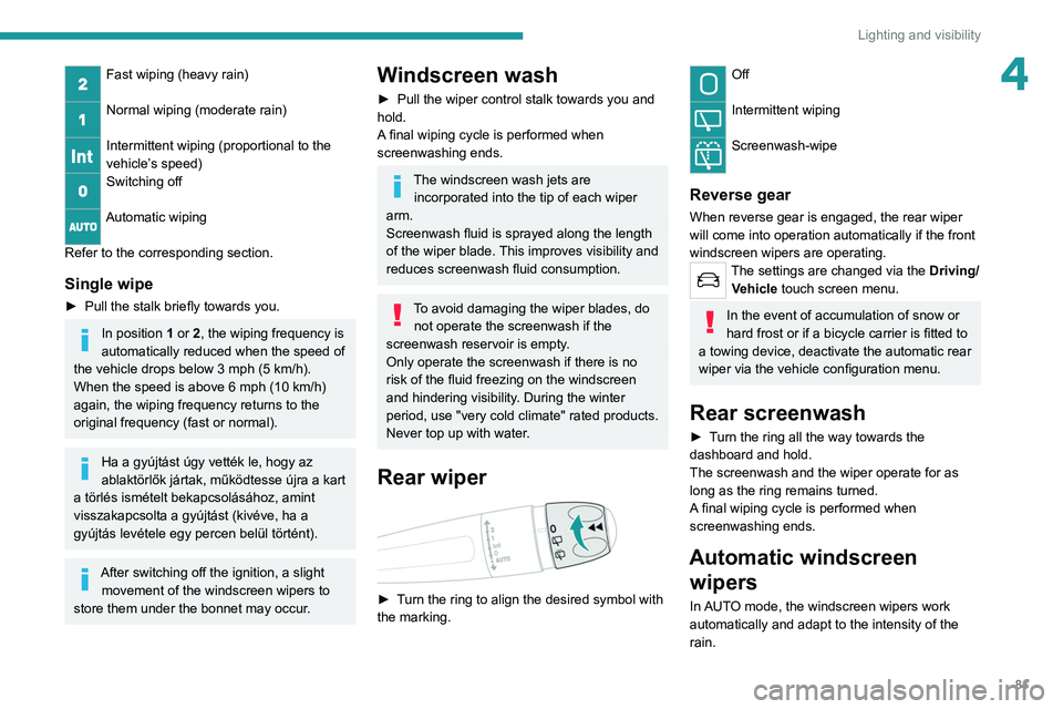
► Turn the ring to align the desired symbol with
the marking.
Off
Intermittent wiping
Screenwash-wipe
Reverse gear
When reverse gear is engaged, the rear wiper
will come into operation automatically if the front
windscreen wipers are operating.
The settings are changed via the Driving/
Vehicle touch screen menu.
In the event of accumulation of snow or
hard frost or if a bicycle carrier is fitted to
a towing device, deactivate the automatic rear
wiper via the vehicle configuration menu.
Rear screenwash
► Turn the ring all the way towards the
dashboard and hold.
The screenwash and the wiper operate for as
long as the ring remains turned.
A final wiping cycle is performed when
screenwashing ends.
Automatic windscreen wipers
In AUTO mode, the windscreen wipers work
automatically and adapt to the intensity of the
rain.
Page 93 of 292
91
Safety
5Switching on
By default, the system is not selected.
The state of the function is not saved when the
ignition is switched off.
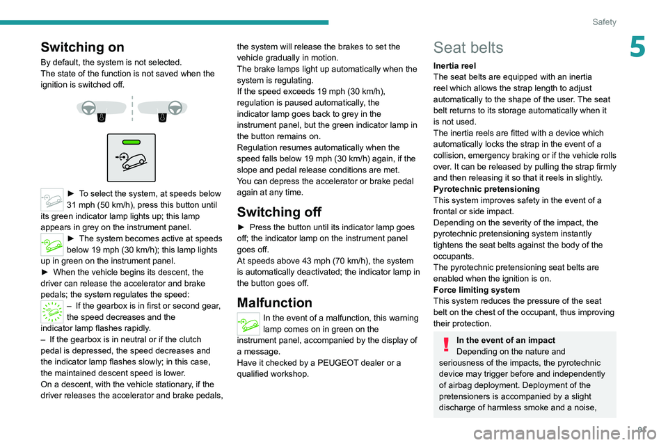
► To select the system, at speeds below
31 mph (50 km/h), press this button until
its green indicator lamp lights up; this lamp
appears in grey on the instrument panel.
► The system becomes active at speeds
below 19 mph (30 km/h); this lamp lights
up in green on the instrument panel.
►
When the vehicle begins its descent, the
driver can release the accelerator and brake
pedals; the system regulates the speed:
– If the gearbox is in first or second gear ,
the speed decreases and the
indicator
lamp flashes rapidly.
–
If the gearbox is in neutral or if the clutch
pedal is depressed, the speed decreases and
the indicator
lamp flashes slowly; in this case,
the maintained descent speed is lower.
On a descent, with the vehicle stationary, if the
driver releases the accelerator and brake pedals, the system will release the brakes to set the
vehicle gradually in motion.
The brake lamps light up automatically when the
system is regulating.
If the speed exceeds 19 mph (30
km/h),
regulation is paused automatically, the
indicator lamp goes back to grey in the
instrument panel, but the green indicator lamp in
the button remains on.
Regulation resumes automatically when the
speed falls below 19 mph (30 km/h) again, if the
slope and pedal release conditions are met.
You can depress the accelerator or brake pedal
again at any time.
Switching off
► Press the button until its indicator lamp goes
off; the indicator lamp on the instrument panel
goes off.
At speeds above 43 mph (70
km/h), the system
is automatically deactivated; the indicator lamp in
the button goes off.
Malfunction
In the event of a malfunction, this warning
lamp comes on in green on the
instrument panel, accompanied by the display of
a message.
Have it checked by a PEUGEOT dealer or a
qualified workshop.
Seat belts
Inertia reel
The seat belts are equipped with an inertia
reel which allows the strap length to adjust
automatically to the shape of the user. The seat
belt returns to its storage automatically when it
is not used.
The inertia reels are fitted with a device which
automatically locks the strap in the event of a
collision, emergency braking or if the vehicle rolls
over. It can be released by pulling the strap firmly
and then releasing it so that it reels in slightly.
Pyrotechnic pretensioning
This system improves safety in the event of a
frontal or side impact.
Depending on the severity of the impact, the
pyrotechnic pretensioning system instantly
tightens the seat belts against the body of the
occupants.
The pyrotechnic pretensioning seat belts are
enabled when the ignition is on.
Force limiting system
This system reduces the pressure of the seat
belt on the chest of the occupant, thus improving
their protection.
In the event of an impact
Depending on the nature and
seriousness of the impacts, the pyrotechnic
device may trigger before and independently
of airbag deployment. Deployment of the
pretensioners is accompanied by a slight
discharge of harmless smoke and a noise,
Page 127 of 292
125
Driving
6– The electric parking brake is being applied.In these cases, this indicator lamp flashes
for a few seconds, then goes off.
Malfunctions
In the event of a fault with the system, this
warning lamp flashes for a few moments
on the instrument panel, then remains on,
accompanied by the display of a message.
Have it checked by a PEUGEOT dealer or a
qualified workshop.
The vehicle stalls in STOP mode
All of the instrument panel warning lamps come
on if there is a fault.
►
Switch off the ignition then start the engine
again with the key or the " ST
ART/STOP" button.
12 V battery
The Stop & Start system requires a
12 V battery of specific technology and
specification.
All work must be carried out only by a
PEUGEOT
dealer or a qualified workshop.
Tyre under-inflation detection
This system alerts the driver when one or more
tyres have a drop in pressure.
The alert is raised when the vehicle is moving,
not when stationary.
It compares the information given by the wheel
speed sensors with reference values, which
must be reinitialised every time the tyre
pressures are adjusted or a wheel changed.
It takes the last values
stored during
the
reinitialisation request into account. It is
therefore essential that the tyre pressure is
correct during the operation. This operation is
the driver’s responsibility.
The tyre under-inflation detection cannot, in any circumstances, replace the need
for vigilance on the part of the driver.
This system does not avoid the need to
regularly check the tyre pressures (including
the spare wheel), especially before a long
journey.
Driving with under-inflated tyres, particularly
in adverse conditions (heavy load, high
speed, long journey):
–
worsens road-holding.
–
lengthens braking distances.
–
causes premature wear of the tyres.
–
increases energy consumption.
The inflation pressures defined for the vehicle can be found on the tyre pressure
label.
For more information on the Identification
markings, refer to the corresponding section.
Checking tyre pressures
This check should be done monthly
when the tyres are "cold" (vehicle stopped for
1 hour or after a journey of less than 6 miles
(10
km) at moderate speeds).
Otherwise, add 0.3 bar to the pressures
shown on the label.
Snow chains
The system does not have to be
reinitialised after fitting or removing snow
chains.
Under-inflation alert
This is signalled by the fixed illumination of this warning lamp, accompanied by an
audible signal and, depending on equipment, the
display of a message.
►
Reduce speed immediately
, avoid excessive
steering movements and avoid sudden braking.
►
Stop the vehicle as soon as it is safe to do
so.
The loss of pressure detected may not always cause visible deformation of the
tyre.
Do not rely on just a visual check.
►
Using a compressor
, such as the one in
the temporary puncture repair kit, check the
pressures of all four tyres when cold.
►
If it is not possible to carry out this check
immediately
, drive carefully at reduced speed.
Page 198 of 292
196
In the event of a breakdown
► Reel in the winch by loosening the winch
control nut with wheelbrace 5 and extension
piece 8: the nut should rotate freely once the
cable is completely reeled in.
► Store the rest of the tools in the storage
areas in the boot sill trim.
The punctured wheel cannot be secured beneath the vehicle; it must be stored in
the boot (use a cover to protect the inside of
the boot).
Putting the winch and spare wheel
back in place
► Place the appropriate tools in the box and
close the cover.
► Place the tool box on the ground.
When the spare wheel is fitted in place of
a wheel with a punctured tyre, the winch
and tool box must be placed beneath the
vehicle again before restarting.
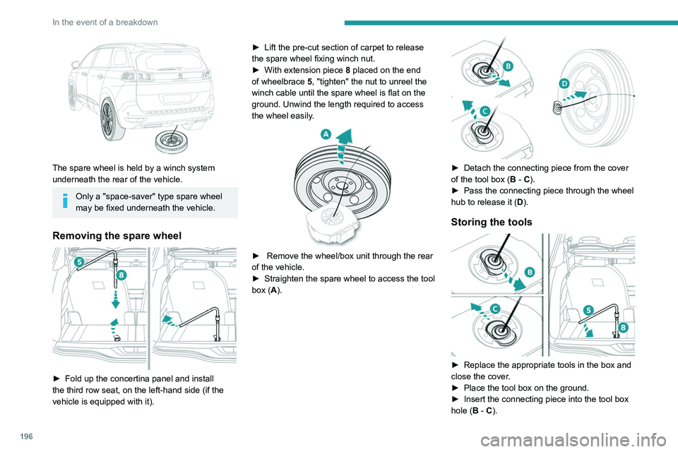
The spare wheel is held by a winch system
underneath the rear of the vehicle.
Only a "space-saver" type spare wheel
may be fixed underneath the vehicle.
Removing the spare wheel
► Fold up the concertina panel and install
the third row seat, on the left-hand side (if the
vehicle is equipped with it). ►
Lift the pre-cut section of carpet to release
the spare wheel
fixing winch nut.
►
With extension piece
8
placed on the end
of wheelbrace 5, "tighten" the nut to unreel the
winch cable until the spare wheel is flat on the
ground. Unwind the length required to access
the wheel easily.
► Remove the wheel/box unit through the rear
of the vehicle.
►
Straighten the spare wheel to access the tool
box (
A).
► Detach the connecting piece from the cover
of the tool box ( B - C).
►
Pass the connecting piece through the wheel
hub to release it ( D
).
Storing the tools
► Replace the appropriate tools in the box and
close the cover .
►
Place the tool box on the ground.
►
Insert the connecting piece into the tool box
hole (
B - C).