height adjustment Peugeot 308 2017 Owner's Manual
[x] Cancel search | Manufacturer: PEUGEOT, Model Year: 2017, Model line: 308, Model: Peugeot 308 2017Pages: 392, PDF Size: 10.16 MB
Page 4 of 392
.
.
308_en_Chap00a_sommaire_ed01-2016
Over view
Instrument panel 12
Indicator and warning lamps
1
3
ga
uges and indicators
2
8
Distance recorders
3
5
tr
ip computer
3
7
to
uch screen
4
0
Setting the date and time
4
7Remote control key
5
0
"Keyless e
n
try and Starting" with remote
control 56
"Keyless e
n
try and Starting"
5
8
Boot
61
Alarm
6
7
el
ectric windows
7
0
P
e
uge
Ot
i- Cockpit
7
2
Steering wheel adjustment
7
2
Front seats
7
3
Rear seats (hatchback)
7
9
Rear seats (SW)
8
0
Interior fittings 8 2
Front armrest
8
4
Boot fittings (hatchback)
87
B
oot fittings (SW)
8
8
Heating and Ventilation
9
1
Manual air conditioning
9
3
Manual air conditioning (
to
uch screen)
9
4
Dual-zone digital air conditioning (
to
uch screen)
9
5
Front demist - defrost
1
00
Rear screen demist - defrost
1
01
Panoramic sunroof
1
02
Courtesy lamps
1
03
Interior mood lighting
1
04Mirrors
105
Lighting control stalk
1
07
Daytime running lamps
1
10
Automatic illumination of headlamps
1
11
Direction indicators
1
12
Side spotlamps
1
13
Headlamp beam height adjustment
1
13
Wiper control stalk
1
14
Automatic rain sensitive wipers
1
16
Hazard warning lamps
1
18em
ergency or assistance 1 19
H or n 121
el
ectronic stability control (
e
SC)
1
21
Seat belts
1
24
Airbags
127
Carrying children
1
31
Deactivating the passenger front airbag
1
34
ISOFIX mountings and child seats
1
40
Child lock
1
44
eco-driving
In struments Access
ea
se of use and comfort Lighting and visibility
Safety
Contents
Page 74 of 392

72
308_en_Chap03_ergonomie-et-confort_ed01-2016
Steering wheel adjustment
F When stationary, lower the control lever
to release the steering wheel adjustment
mechanism.
F
A
djust the height and reach to suit your
driving position.
F
P
ull the control lever to lock the steering
wheel adjustment mechanism.
As a safety precaution, these
operations should only be carried out
while the vehicle is stationary.
PeugeOt i -Cockpit
Before taking to the road and to make the most
of the special ergonomics of the Pe
ugeOt
i- Cockpit, carry out these adjustments in the
following order:
-
hea
d restraint height,
-
b
ackrest angle,
-
sea
t cushion height,
-
s
eat longitudinal position,
-
s
teering wheel reach and then height
-
t
he interior and door mirrors.
Once these adjustments have been made,
ensure that from your driving position you can
see the "head-up" instrument panel clearly,
over the reduced diameter steering wheel.
Before moving the seat backwards,
ensure that there is nothing that might
prevent the full travel of the seat, so as
to avoid the risk of jamming the seat
caused by the presence of objects
on the floor behind the seat or rear
passengers. If the seat jams, stop the
movement immediately.
ease of use and comfort
Page 75 of 392
73
308_en_Chap03_ergonomie-et-confort_ed01-2016
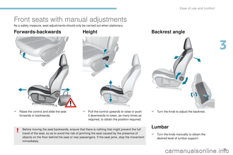
Front seats with manual adjustments
F Raise the control and slide the seat forwards or backwards. F
P ull the control upwards to raise or push
it downwards to lower, as many times as
required, to obtain the position required. F
tu rn the knob to adjust the backrest.
Forwards-backwards
HeightBackrest angle
As a safety measure, seat adjustments should only be carried out when stationary.
F t
u
rn the knob manually to obtain the
desired level of lumbar support.
LumbarBefore moving the seat backwards, ensure that there is nothing that might prevent the full
travel of the seat, so as to avoid the risk of jamming the seat caused by the presence of
objects on the floor behind the seat or rear passengers. If the seat jams, stop the movement
immediately.
3
ease of use and comfort
Page 76 of 392

74
308_en_Chap03_ergonomie-et-confort_ed01-2016
electric driver's seat
Forwards-backwardsSeat backrest angleSeat cushion height and
angle
to avoid discharging the battery, carry out
these adjustments with the engine running.
F Push the control for wards or rear wards to
slide the seat. F
ti lt the control for wards or rear wards to
adjust the angle of the seat backrest. F
ti p the rear of the control upwards or
downwards to obtain the desired height.
F
t
i
p the front of the control upwards or
downwards to obtain the desired angle.
Before moving the seat backwards, ensure that there is nothing that might prevent the full
travel of the seat, so as to avoid the risk of jamming the seat caused by the presence of
objects on the floor behind the seat or rear passengers. If the seat jams, stop the movement
immediately.
ease of use and comfort
Page 79 of 392

77
308_en_Chap03_ergonomie-et-confort_ed01-2016
Electric lumbar adjustment
F Press the control to obtain the desired lumbar support.
F
t
o r
aise the head restraint, pull it upwards.
F
t
o r
emove the head restraint, press the
lug
A and pull the head restraint upwards.
F
t
o p
ut the head restraint back in place,
engage the head restraint stems in the
openings keeping them in line with the seat
backrest.
F
t
o l
ower the head restraint, press the lug A
and the head restraint at the same time.
th
e head restraint is fitted with a frame
with notches which prevents it from
lowering; this is a safety device in case
of impact.
The adjustment is correct when the
upper edge of the head restraint is
level with the top of the head.
Never drive with the head restraints
removed; they must be in place and
adjusted correctly.
Head restraint height
3
ease of use and comfort
Page 86 of 392
84
308_en_Chap03_ergonomie-et-confort_ed01-2016
F to connect a 12 V accessory (maximum power: 120 Watts), lift the cover and
connect a suitable adaptor.
12 V accessory
socket
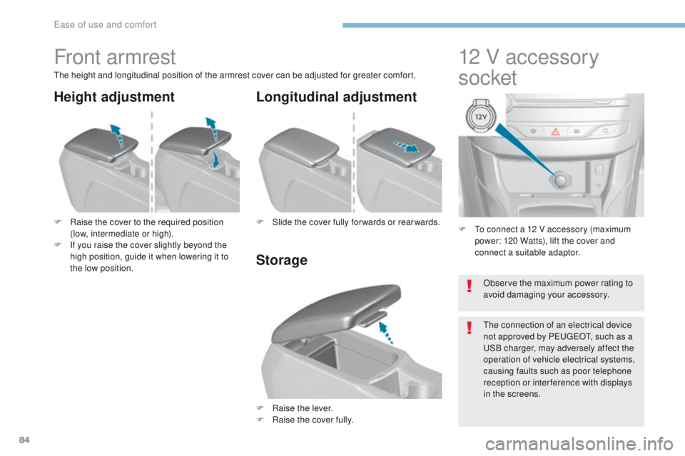
Front armrest
the height and longitudinal position of the armrest cover can be adjusted for greater comfort.
F
R
aise the cover to the required position
(low, intermediate or high).
F
I
f you raise the cover slightly beyond the
high position, guide it when lowering it to
the low position.
F
Ra
ise the lever.
F
Ra
ise the cover fully.
F
S
lide the cover fully for wards or rear wards.
Storage Longitudinal adjustment
Height adjustment
Observe the maximum power rating to
avoid damaging your accessory.
th
e connection of an electrical device
not approved by P
e
uge
Ot, s
uch as a
uS
B charger, may adversely affect the
operation of vehicle electrical systems,
causing faults such as poor telephone
reception or inter ference with displays
in the screens.
ease of use and comfort
Page 115 of 392
113
308_en_Chap04_eclairage-et-visibilite_ed01-2016
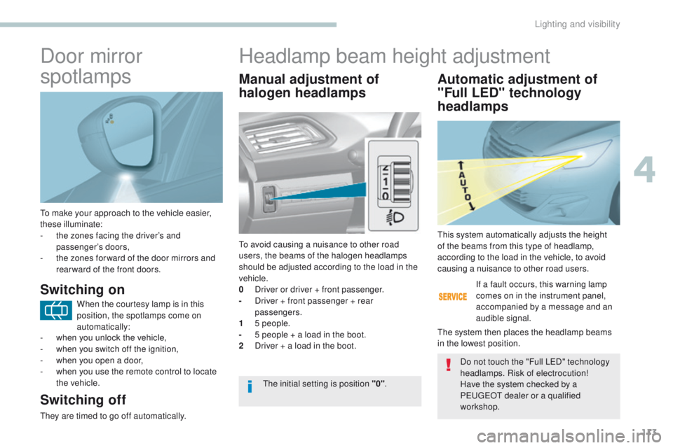
to make your approach to the vehicle easier,
these illuminate:
-
t
he zones facing the driver’s and
passenger’s doors,
-
t
he zones for ward of the door mirrors and
rear ward of the front doors.
Door mirror
spotlamps
Switching on
Switching off
they are timed to go off automatically.
Manual adjustment of
halogen headlamps Automatic adjustment of
"Full LED" technology
headlamps
to avoid causing a nuisance to other road
users, the beams of the halogen headlamps
should be adjusted according to the load in the
vehicle.
0
D
river or driver + front passenger.
-
D
river + front passenger + rear
passengers.
1
5
people.
-
5 p
eople + a load in the boot.
2
D
river + a load in the boot. If a fault occurs, this warning lamp
comes on in the instrument panel,
accompanied by a message and an
audible signal.th
is system automatically adjusts the height
of the beams from this type of headlamp,
according to the load in the vehicle, to avoid
causing a nuisance to other road users.
th
e system then places the headlamp beams
in the lowest position.
th
e initial setting is position "0" .Do not touch the "Full L
eD
" technology
headlamps. Risk of electrocution!
Have the system checked by a
P
e
uge
Ot
dealer or a qualified
workshop.
Headlamp beam height adjustment
When the courtesy lamp is in this
position, the spotlamps come on
automatically:
-
w
hen you unlock the vehicle,
-
w
hen you switch off the ignition,
-
w
hen you open a door,
-
w
hen you use the remote control to locate
the vehicle.
4
Lighting and visibility
Page 140 of 392
138
308_en_Chap05_securite_ed01-2016
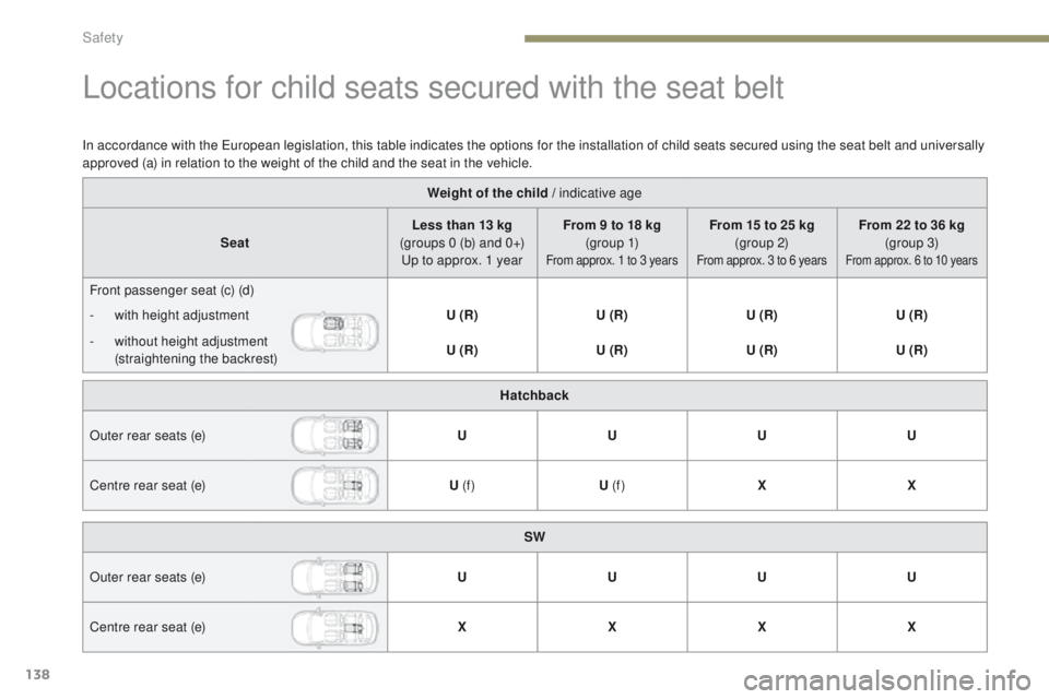
Locations for child seats secured with the seat belt
Weight of the child / indicative age
Seat Less than 13 kg
(groups 0 (b) and 0+)
up t
o approx. 1 year From 9 to 18 kg
(g r o u p 1)
From approx. 1 to 3 years
From 15 to 25 kg (group 2)
From approx. 3 to 6 years
From 22 to 36 kg (group 3)
From approx. 6 to 10 years
Front passenger seat (c) (d)
-
w
ith height adjustment U (R)U (R)U (R)U (R)
-
w
ithout height adjustment
(straightening the backrest) U (R)
U (R)U (R)U (R)
In accordance with the
e
u
ropean legislation, this table indicates the options for the installation of child seats secured using the seat belt and universally
approved (a) in relation to the weight of the child and the seat in the vehicle.
Hatchback
Outer rear seats (e) UUUU
Centre rear seat (e) U (f )U (f ) XX
SW
Outer rear seats (e) UUUU
Centre rear seat (e) XXXX
Safety
Page 146 of 392
144
308_en_Chap05_securite_ed01-2016
IUF Seat suitable for the installation of an Isofix U niversal seat, F or ward facing
secured using the upper strap.
IL- SU
S
eat suitable for the installation of an
I sofix S emi-Universal seat either:
-
r
ear ward facing fitted with an upper strap
or a support leg,
-
f
or ward facing fitted with a support leg,
-
a
n infant car seat fitted with an upper strap
or a support leg. For more information on ISOFIX
mountings and child seats
and in
particular the upper strap, refer to the
corresponding section.
X
S
eat not suitable for the installation of a
child seat of the weight group indicated.
(a)
M
ove a seat without height adjustment
for wards by 1 notch from the mid position
for wards and backwards. A seat with
height adjustment must be in the highest
position.
(b)
t
h
e installation of an infant carrier on one
of the outer seats makes use of the other
two seats impossible.
(c)
A s
eat with height adjustment must be
placed in the highest position. Move the
seat without height adjustment for ward by
5 notches from the mid-position for wards
and backwards. Remove and stow the head restraint
before fitting a child seat with a
backrest to a passenger seat.
Refit the head restraint when the child
seat is removed.
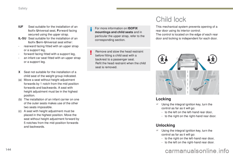
Child lock
this mechanical system prevents opening of a
rear door using its interior control.
th
e control is located on the edge of each rear
door and locking is independent for each door.
Locking
F using the integral ignition key, turn the control as far as it will go:
-
t
o the left on the left-hand rear door,
-
t
o the right on the right-hand rear door.
Unlocking
F using the integral ignition key, turn the control as far as it will go:
-
t
o the right on the left-hand rear door,
-
t
o the left on the right-hand rear door.
Safety