battery location PEUGEOT 308 2023 Owners Manual
[x] Cancel search | Manufacturer: PEUGEOT, Model Year: 2023, Model line: 308, Model: PEUGEOT 308 2023Pages: 260, PDF Size: 7.97 MB
Page 12 of 260
10
Dashboard instruments
Driver information
Instrument panel
The instrument panel displays all the information
the driver needs about the status of the vehicle's
various systems.
This information appears in the form of warning
and indicator lamps and messages.
The instrument panel is in the form of a fully
digital screen.
Digital instrument panels
Digital instrument panels are of the head-up or
3D head-up type.
They can be personalised using a system of
pages and widgets.
Depending on the page displayed, certain
information is not displayed or is presented
differently.
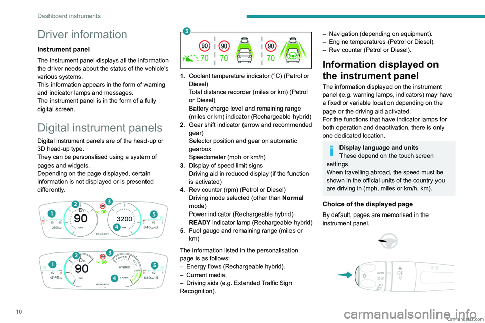
1. Coolant temperature indicator (°C) (Petrol or
Diesel)
Total distance recorder (miles or km) (Petrol
or Diesel)
Battery charge level and remaining range
(miles or km) indicator (Rechargeable hybrid)
2. Gear shift indicator (arrow and recommended
gear)
Selector position and gear on automatic
gearbox
Speedometer (mph or km/h)
3. Display of speed limit signs
Driving aid in reduced display (if the function
is activated)
4. Rev counter (rpm) (Petrol or Diesel)
Driving mode selected (other than Normal
mode)
Power indicator (Rechargeable hybrid)
READY indicator lamp (Rechargeable hybrid)
5. Fuel gauge and remaining range (miles or
km)
The information listed in the personalisation
page is as follows:
–
Energy flows (Rechargeable hybrid).
–
Current media.
–
Driving aids (e.g.
Extended Traffic Sign
Recognition).
– Navigation (depending on equipment).
– Engine temperatures (Petrol or Diesel).
–
Rev counter (Petrol or Diesel).
Information displayed on
the instrument panel
The information displayed on the instrument
panel (e.g. warning lamps, indicators) may have
a fixed or variable location depending on the
page or the driving aid activated.
For the functions that have indicator lamps for
both operation and deactivation, there is only
one dedicated location.
Display language and units
These depend on the touch screen
settings.
When travelling abroad, the speed must be
shown in the official units of the country you
are driving in (mph, miles or km/h, km).
Choice of the displayed page
By default, pages are memorised in the
instrument panel.
CarM an uals 2 .c o m
Page 80 of 260
78
Safety
– The indicator lamp flashes red: emergency
battery is flat. This will be recharged after a few
minutes' driving.
–
The indicator lamp is fixed red: system
malfunction.
The emergency and assistance call
services may not work.
–
If the indicator lamp does not light up when
the ignition is turned on, this is also a system
malfunction.
If the problem persists, contact a qualified
workshop as soon as possible.
The malfunction of the system does not prevent the vehicle from driving.
When an onboard system update is
being performed, the eCall (SOS)
function is not available.
Data processing
All processing of personal data by
the eCall (SOS) function complies with
the framework for protection of personal
information established by Regulation
2016/679 (General Data Protection
Regulation - GDPR) and Directive 2002/58/
EC of the European Parliament and the
Council, and in particular, seeks to protect
the vital interests of the data subject, in
accordance with Article 6 (1) d) GDPR.
The processing of personal data is strictly
limited to the purpose of handling the eCall
(SOS) function used with the “112” single
European emergency call number.
The eCall (SOS) function is only able to
collect and process the following data
relating to the vehicle: vehicle identification
number, vehicle type (passenger vehicle or
light commercial vehicle), fuel type or power
source, three most recent locations and
direction of travel, number of passengers
and a timestamped log file of the automatic
activation of the system and its timestamp.
The recipients of the processed data are the
emergency call handling centres designated
by the relevant national authorities in the
territory in which they are located, enabling
priority routing and handling of calls to the
“112” emergency number.
Data storage
Data contained in the system’s memory
is not accessible from outside the system until
a call is made. The system is not traceable
and is not continuously monitored in its
normal operating mode.
The data in the system's internal memory is
automatically and continuously erased. Only
the vehicle’s three most recent locations,
necessary for the normal functioning of the
system, are stored.
When an emergency call is triggered, the data
log is stored for no more than 13 hours.
Access to data
You have the right of access to data and
as appropriate to request the rectification,
erasure or restriction of processing of any
personal data not processed in accordance
with the provisions of GDPR. Third parties
to which data has been disclosed shall
be notified of any rectification, erasure or
restriction carried out in compliance with
GDPR, unless it proves impossible or
involves a disproportionate effort.
You also have the right to lodge a complaint
with the respective data protection
supervisory authority.
If you want to claim your above-mentioned
rights please contact us per email at:
[email protected].
For more information regarding our contact
details please take a look at our Privacy &
Cookies Policy on the brand's website. CarM an uals 2 .c o m
Page 153 of 260
151
Practical information
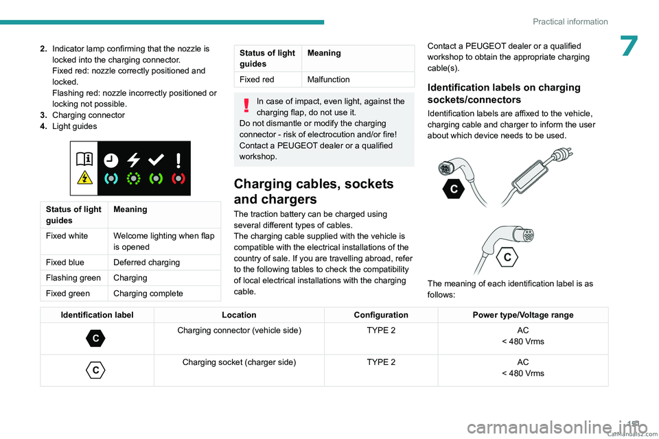
72.Indicator lamp confirming that the nozzle is
locked into the charging connector.
Fixed red: nozzle correctly positioned and
locked.
Flashing red: nozzle incorrectly positioned or
locking not possible.
3. Charging connector
4. Light guides
Status of light
guides Meaning
Fixed white Welcome lighting when flap
is opened
Fixed blue Deferred charging
Flashing green Charging
Fixed green Charging complete
Status of light
guides Meaning
Fixed red Malfunction
In case of impact, even light, against the
charging flap, do not use it.
Do not dismantle or modify the charging
connector - risk of electrocution and/or fire!
Contact a PEUGEOT dealer or a qualified
workshop.
Charging cables, sockets
and chargers
The traction battery can be charged using
several different types of cables.
The charging cable supplied with the vehicle is
compatible with the electrical installations of the
country of sale. If you are travelling abroad, refer
to the following tables to check the compatibility
of local electrical installations with the charging
cable. Contact a PEUGEOT dealer or a qualified
workshop to obtain the appropriate charging
cable(s).
Identification labels on charging
sockets/connectors
Identification labels are affixed to the vehicle,
charging cable and charger to inform the user
about which device needs to be used.
The meaning of each identification label is as
follows:
Identification label LocationConfigurationPower type/Voltage range
C
Charging connector (vehicle side) TYPE 2AC
< 480 Vrms
C
Charging socket (charger side) TYPE 2AC
< 480 Vrms CarM an uals 2 .c o m
Page 167 of 260
165
Practical information
7It is strongly recommended that you
practise fitting the snow chains on a level
and dry surface before setting off.
Avoid driving with snow chains on roads that have been cleared of snow to avoid
damaging the vehicle's tyres and the road
surface. If the vehicle is fitted with alloy
wheels, check that no part of the chain or its
fixings is in contact with the wheel rim.
Energy economy mode
This system manages the duration of use of
certain functions, in order to conserve a sufficient
level of charge in the battery with the ignition off.
After switching off the engine and for a maximum
cumulative period of around 30 minutes, you can
continue to use functions such as the audio and
telematics system, dipped beam headlamps or
courtesy lamps.
Selecting the mode
A confirmation message is displayed when
energy economy mode is entered, and the active
functions are placed on standby.
If a telephone call is in progress at the
time, it will be maintained for around 10
minutes via the audio system’s hands-free
system.
Exiting the mode
These functions are automatically reactivated the
next time the vehicle is used.
To restore the use of these functions
immediately, start the engine and let it run:
–
For less than 10 minutes, to use the
equipment for approximately 5 minutes.
–
For more than 10 minutes, to use the
equipment for approximately 30 minutes.
Let the engine run for the specified duration to
ensure that the battery charge is sufficient.
T
o recharge the battery, avoid repeatedly or
continuously restarting the engine.
A flat battery prevents the engine from starting.
For more information on the 12
V battery,
refer to the corresponding section.
Load reduction mode
This system manages the use of certain
functions according to the level of charge
remaining in the battery.
When the vehicle is being driven, the load
reduction function temporarily deactivates certain
functions, such as the air conditioning and the
heated rear screen.
The deactivated functions are reactivated
automatically as soon as conditions permit.
Bonnet
Stop & Start
Before doing anything under the bonnet,
you must switch off the ignition to avoid any
risk of the engine restarting automatically.
Take care with objects or clothing that could
be caught in the blades of the cooling fan
or in certain moving components - risk of
strangulation and serious injury!
Rechargeable hybrid vehicles
Before any work is carried out under the
bonnet, it is essential to switch off the ignition
and disconnect the charging connector nozzle
if it is connected, check that the READY
indicator lamp is off on the instrument panel
and wait 4 minutes - risk of serious injury!
The location of the interior bonnet release lever prevents the bonnet being
opened when the left-hand front door is
closed. CarM an uals 2 .c o m
Page 168 of 260
166
Practical information
When the engine is hot, handle the
exterior safety catch and the bonnet stay
with care (risk of burns), using the protected
area.
When the bonnet is open, take care not to
damage the safety catch.
Do not open the bonnet under very windy
conditions.
Cooling of the engine when stopped
The engine cooling fan may start after
the engine has been switched off.
Take care with objects or clothing that
could be caught in the blades of the fan!
Opening
► Open the left- hand front door.
► Pull the interior release lever , located at the
bottom of the door frame, towards you.
► Lift the exterior safety catch and raise the
bonnet.
►
Unclip the stay from its housing and place it
in the support slot to hold the bonnet open.
Closing
► Lower the bonnet and release it near the end
of its travel.
►
Check the locking.
Because of the presence of electrical
equipment under the bonnet, it is strongly
recommended that exposure to water (rain,
washing, etc.) be limited.
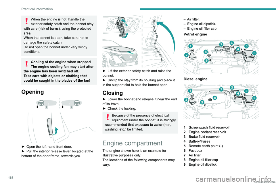
Engine compartment
The engine shown here is an example for
illustrative purposes only.
The locations of the following components may
vary: –
Air filter
.
–
Engine oil dipstick.
–
Engine oil filler cap.
Petrol engine
Diesel engine
1.
Screenwash fluid reservoir
2. Engine coolant reservoir
3. Brake fluid reservoir
4. Battery/Fuses
5. Remote earth point (-)
6. Fusebox
7. Air filter
8. Engine oil filler cap
9. Engine oil dipstick CarM an uals 2 .c o m