height adjustment Peugeot 508 Hybrid 2014 Owner's Manual
[x] Cancel search | Manufacturer: PEUGEOT, Model Year: 2014, Model line: 508 Hybrid, Model: Peugeot 508 Hybrid 2014Pages: 380, PDF Size: 10.94 MB
Page 10 of 380
8
508_en_Chap00b_vue-ensemble_ed02-2014
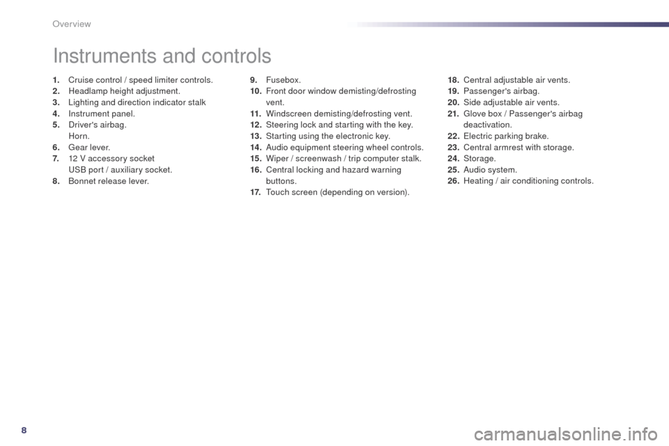
9. Fusebox.
10. F ront door window demisting/defrosting
vent.
11.
W
indscreen demisting/defrosting vent.
12 .
S
teering lock and starting with the key.
13.
S
tarting using the electronic key.
14 .
A
udio equipment steering wheel controls.
15.
W
iper / screenwash / trip computer stalk.
16.
C
entral locking and hazard warning
buttons.
17.
t
ou
ch screen (depending on version).
Instruments and controls
1. Cruise control / speed limiter controls.
2. Headlamp height adjustment.
3.
L
ighting and direction indicator stalk
4.
I
nstrument panel.
5.
D
river's airbag.
Horn.
6.
g
ea
r lever.
7.
1
2 V accessory socket
u
S
B port / auxiliary socket.
8.
B
onnet release lever. 18. C
entral adjustable air vents.
19. P assenger's airbag.
20.
S
ide adjustable air vents.
21.
g
l
ove box / Passenger's airbag
deactivation.
22.
e
l
ectric parking brake.
23.
C
entral armrest with storage.
24.
Storage.
25.
A
udio system.
26.
H
eating / air conditioning controls.
Over view
Page 68 of 380

66
508_en_Chap03_confort_ed02-2014
Comfort
Front seats
Manual adjustments
1. Adjustments to the height and angle of the head restraint
t
o r
aise it, pull upwards.
t
o l
ower it, hold the button in and
press
on the head restraint (pushing
to
go past the stiff point of the button).
2.
A
djustment of the backrest angle
O
perate the control lever and adjust
the
position of the backrest to the front
or
to the rear.
3.
A
djustment of the seat height
R
aise or lower the control lever the
number
of times required to obtain
the
desired position.
4.
A
djustment of the lumbar suppor t
t
h
is system allows the height and
depth
of the lumbar support to be
adjusted
separately.
F
F
or wards or backwards to increase
or
decrease the lumbar support.
F
u
p
wards or downwards to raise or
lower
the lumbar contact zone.
5.
F
orwards-backwards adjustment of
the
seat position
L
ift the control bar and slide the seat
forwards or backwards.
6.
A
djusting the cushion
P
ull the handle to adjust the length of the
cushion. Before moving the seat backwards, ensure that there is nothing that might prevent the full
travel of the seat, so as to avoid the risk of of jamming the seat caused by the presence of
objects on the floor behind the seat or rear passengers. If the seat jams, stop the movement
immediately.
Page 69 of 380

67
508_en_Chap03_confort_ed02-2014
Electric adjustments
1. Adjustment of the seat cushion angle and height, and forwards-backwards
adjustment
F
R
aise or lower the front of the control to
adjust the seat cushion angle.
F
R
aise or lower the rear of the control to
raise or lower the seat.
F
S
imultaneously raise or lower the front
and rear of the control in order to raise or
lower the entire seat.
2.
A
djustment of the backrest angle
M
ove the control for wards or backwards to
adjust the backrest angle.
3.
A
djustment of lumbar support
t
h
is function allows you to independently
adjust the height and level of lumbar
support.
Move the control:
F
F
or wards or backwards to increase or
reduce the lumbar support.
F
u
p
wards or downwards to raise or lower
the lumbar support zone.
Before moving the seat backwards, ensure that there is nothing that might prevent the full
travel of the seat, so as to avoid the risk of of jamming the seat caused by the presence of
objects on the floor behind the seat or rear passengers. If the seat jams, stop the movement
immediately. Switch on the ignition or start the engine if the vehicle has gone into economy mode.
th
e electric functions of the driver's seat are active for about a minute after opening the
front door.
t
h
ey are deactivated about a minute after switching off the ignition and in
economy mode.
to r
eactivate them, switch on the ignition.
3
Comfort
Page 71 of 380
69
508_en_Chap03_confort_ed02-2014
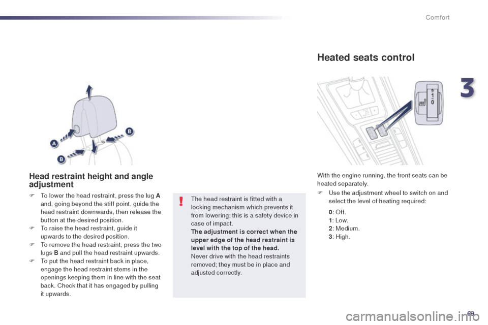
Head restraint height and angle
adjustment
F to lower the head restraint, press the lug A and, going beyond the stiff point, guide the
head restraint downwards, then release the
button at the desired position.
F
t
o r
aise the head restraint, guide it
upwards to the desired position.
F
t
o r
emove the head restraint, press the two
lugs B and pull the head restraint upwards.
F
t
o p
ut the head restraint back in place,
engage the head restraint stems in the
openings keeping them in line with the seat
back. Check that it has engaged by pulling
it upwards.th e head restraint is fitted with a
locking mechanism which prevents it
from lowering; this is a safety device in
case of impact.
The adjustment is correct when the
upper edge of the head restraint is
level with the top of the head.
Never drive with the head restraints
removed; they must be in place and
adjusted correctly.
Heated seats control
F use the adjustment wheel to switch on and select the level of heating required:
With the engine running, the front seats can be
heated separately.
0: Of f.
1 : Low.
2 : Medium.
3 : High.
3
Comfort
Page 77 of 380
75
508_en_Chap03_confort_ed02-2014
Automatic day/night model
By means of a sensor, which measures the
light from the rear of the vehicle, this system
automatically and progressively changes
between the day and night uses.
Adjustable mirror providing a central rearward
view.
eq
uipped with an anti-dazzle system, which
darkens the mirror glass and reduces the
nuisance to the driver caused by the sun,
headlamps from other vehicles...
Rear view mirror
Manual day/night model
Adjustment
F Adjust the mirror so that the glass is directed correctly in the "day" position.
Day / night position
F Pull the lever to change to the "night" anti-dazzle position.
F
P
ush the lever to change to the normal
"day" position. In order to ensure optimum visibility
during your manoeuvres, the mirror
lightens automatically when reverse
gear is engaged.
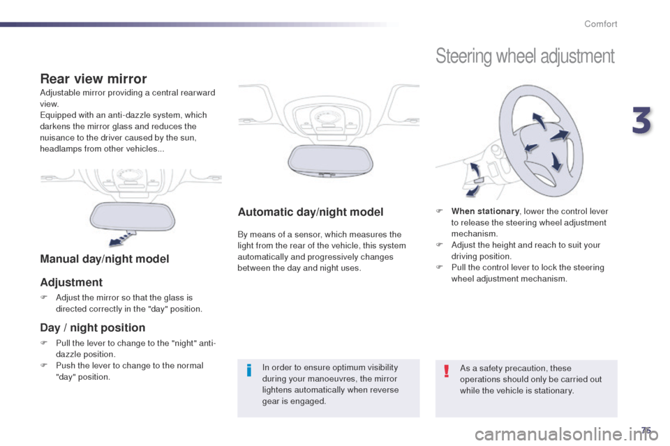
Steering wheel adjustment
F When stationary
, lower the control lever
to release the steering wheel adjustment
mechanism.
F
A
djust the height and reach to suit your
driving position.
F
P
ull the control lever to lock the steering
wheel adjustment mechanism.
As a safety precaution, these
operations should only be carried out
while the vehicle is stationary.
3
Comfort
Page 126 of 380

124
Head-up display
System which projects various information onto
a smoked strip in the field of vision of the driver
so that they do not have to take their eyes off
the road.1.
H
ead-up display on.
2.
H
ead-up display off (long press).
3.
Br
ightness adjustment.
4.
D
isplay height adjustment.Buttons
Once the system has been activated, the
following information is grouped together in the
head-up display:
A.
t
h
e speed of your vehicle.
B.
C
ruise control/speed limiter information.
Displays during operation
C. Navigation information (according to ve r s i o n).
For more information on the navigation
system, refer to the "Audio and
telematic" section.
th
is system operates when the engine is
running and the settings are stored when the
ignition is switched off.
Driving
Page 127 of 380

125
F With the engine running, press button 1 to activate the system and deploy the strip.
F
P
ress and hold button 2 to deactivate the
system and retract the strip.
th
e activated/deactivated state is saved and
restored on restarting the engine.
Activation / Deactivation
F With the engine running, adjust the brightness of the information displayed
using buttons 3 :
-
t
he "sun" to increase the brightness,
-
t
he "moon" to decrease the brightness.
Brightness adjustment
We recommend that adjustments are
made using these buttons only when
the vehicle is stationary.
When stationary or while driving, no
objects should be placed around the
strip (or in its recess) so as to not
impede deployment of the strip and its
correct operation.
In certain extreme weather conditions
(rain and/or snow, bright sunshine, ...)
the head-up display may not be legible
or may suffer temporary interference.
Some sunglasses may hamper reading
of the information.
to c
lean the strip, use a clean, soft
cloth (such as a spectacles cloth or
microfibre cloth). Do not use a dry or
abrasive cloth or detergent or solvent
products as these could scratch the
strip or damage the non-reflective
coating.
Height adjustment
F With the engine running, adjust the display to the desired height using buttons 4 :
-
u
p to move the display up,
-
d
own to move the display down.
4
Driving
Page 148 of 380

146
508_en_Chap05_visibilite_ed02-2014
Manual adjustment
of halogen
headlampsAutomatic adjustment of "full LeD
"
technology headlamps
to avoid causing a nuisance to other road
users, the beams of the halogen headlamps
should be adjusted according to the load in the
vehicle.
0
D
river or driver + front passenger.
-
D
river + front passenger + rear
passengers.
1
5
people.
-
5 p
eople + a load in the boot.
2
D
river + a load in the boot. If a fault occurs, this
warning lamp is displayed
in the instrument panel,
accompanied by an audible signal and a
message in the instrument panel screen.
th
e system then places your headlamps in the
lowest position. In order to avoid causing a nuisance to other
road users, this system corrects the height of
the "full L
e
D
" headlamps beam automatically,
in relation to the load in the vehicle. If a fault occurs, do not touch the "full
L
eD
" bulbs. Contact a P
e
uge
Ot
dealer or a qualified workshop.
th
e initial setting is position "0" .
Travelling abroad
the design of the dipped beam
headlamps allows, without modification,
driving in a country that drives on the
other side of the road to the country in
which your vehicle was sold.
Visibility
Page 182 of 380

180
508_en_Chap07_securite_ed02-2014
Front seat belt height adjustment
F to adjust the anchorage point, squeeze the control and slide it until you find a notch.
From approximately 12 mph
(20
km/h), the warning lamp(s) flash
for two
minutes accompanied by an
audible signal. Once these two minutes
have elapsed, the warning lamp(s) remain on until
the driver or one or more passengers fasten their
seat belt.
Seat belt not fastened /
unfastened warning lamps
1. Front and/or rear seat belts not fastened / unfastened warning lamp in the instrument
panel.
2.
F
ront left seat belt warning lamp.
3.
F
ront right seat belt warning lamp.
4.
R
ear right seat belt warning lamp.
5.
R
ear centre seat belt warning lamp.
6.
R
ear left seat belt warning lamp.
Front and rear seat belt warning
lamps
On switching on the ignition, warning
lamp 1 comes on in the instrument
panel and the corresponding warning
lamp ( 2 to 6) comes on in red in the
passenger's seat belt and front airbag warning
lamp display if the corresponding seat belt is
not fastened or is unfastened.
Safety
Page 363 of 380

361
508_en_Chap12_recherche-visuelle_ed02-2014
Visual search
exterior
Remote control key / electronic key 4 1- 51
-
ope
ning / closing
-
a
nti-theft protection
-
starting
-
battery Welcome lighting
1
45
Door mirror spotlamps
1
45
Additional headlamps
1
47
Secondary additional headlamps
1
48
Headlamp height adjustment
1
46
Changing front bulbs
2
00-202
Wipers
149-152
Changing a wiper blade 1 52, 220
D o o r s
42- 51
-
K
eyless e
n
try and Starting
-
ope
ning / closing
-
c
entral locking
-
em
ergency control
Alarm
52-53
el
ectric windows
5
4-55
Fuel tank, misfuel prevention
6
3-65
Sunroof
6
0 - 61
Roof bars
2
25
Accessories
2
27-228
ty
re under-inflation detection
1
74-175
e
SC: ABS-
eB
FD, e
B
A, ASR,
D S C
17
6 -178
Changing a wheel
1
92-198
-
tools
-
r
emoving / refitting
Snow chains
1
99
ty
re pressures
2
64
Boot
4
4, 56, 59
-
ope
ning / closing
-
em
ergency release
te
mporary puncture repair kit
1
86-191
Changing bulbs
2
03, 206
-
r
ear lamps
-
3
rd brake lamp
-
n
umber plate lamps
Parking sensors
1
34-136
to
wbar
223-224
to
wing
221-222 Door mirrors
7
3 -74
Blind spot monitoring
1
26-128
Saloon
.