PEUGEOT BOXER 2015 Owners Manual
Manufacturer: PEUGEOT, Model Year: 2015, Model line: BOXER, Model: PEUGEOT BOXER 2015Pages: 276, PDF Size: 8.99 MB
Page 151 of 276
149When using a high pressure washer
on stubborn dirt, do not persist on
the headlamps, the lamps and their edges
to avoid damaging their lacquer finish and
seals.
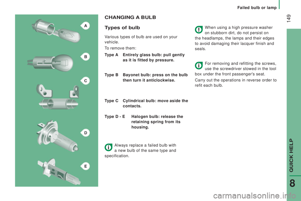
cHAnGInG A BuLB
t
ypes of bulb
Various types of bulb are used on your
vehicle.
to remove them:
type A Entirely glass bulb: pull gently
as it is fitted by pressure.
type B
Bayonet bulb: press on the bulb
then turn it anticlockwise.
type c
c
ylindrical bulb: move aside the
contacts. For removing and refitting the screws,
use the screwdriver stowed in the tool
box under the front passenger's seat.
Carry out the operations in reverse order to
refit each bulb.
type d - E
Halogen bulb: release the
retaining spring from its
housing.
Always replace a failed bulb with
a new bulb of the same type and
specification.
QuICK HeLP
8
Failed bulb or lamp
Page 152 of 276
150
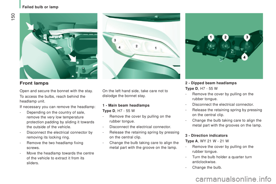
1 - Main beam headlamps
type d, H7 - 55 W
-
Remove the cover by pulling on the
rubber tongue.
-
Disconnect the electrical connector.
-
Release the retaining spring by pressing
on the central clip.
-
Change the bulb taking care to align the
metal part with the groove on the lamp. 2 -
dipped beam headlamps
type d, H7 - 55 W
-
Remove the cover by pulling on the
rubber tongue.
-
Disconnect the electrical connector.
-
Release the retaining spring by pressing
on the central clip.
-
Change the bulb taking care to align the
metal part with the grooves on the lamp.
Front lamps
3 - direction indicators
type A, WY
21 W - 21 W
-
Remove the cover by pulling on the
rubber tongue.
-
t
urn the bulb holder a quarter turn
anticlockwise.
-
Change the bulb.
Open and secure the bonnet with the stay.
to access the bulbs, reach behind the
headlamp unit.
If necessary you can remove the headlamp:
-
Depending on the country of sale,
remove the very low temperature
protection padding by sliding it towards
the outside of the vehicle.
- Disconnect the electrical connector by
removing its locking ring.
-
Remove the two headlamp fixing
screws.
-
Move the headlamp towards the centre
of the vehicle to extract it from its
sliders. On the left hand side, take care not to
dislodge the bonnet stay.
Failed bulb or lamp
Page 153 of 276
151
Halogen bulbs must be changed after
the headlamp has been off for several
minutes (risk of serious burns). Do not touch
the bulb directly with your fingers, use a
lint-free cloth.
When each operation has been completed,
check the operation of the lamps.
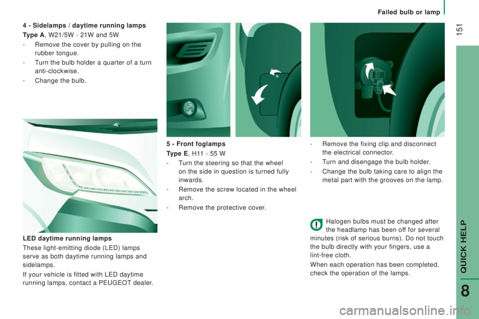
5 - Front foglamps
type E, H1
1 - 55 W
-
t
urn the steering so that the wheel
on the side in question is turned fully
inwards.
-
Remove the screw located in the wheel
arch.
-
Remove the protective cover.
LE
d daytime running lamps
these light-emitting diode (LeD) lamps
serve as both daytime running lamps and
sidelamps.
If your vehicle is fitted with L
eD daytime
running lamps, contact a P
eugeOt dealer.
4 - Sidelamps / daytime running lamps
type A, W21/5W - 21W and 5W
-
Remove the cover by pulling on the
rubber tongue.
-
t
urn the bulb holder a quarter of a turn
anti-clockwise.
-
Change the bulb.
-
Remove the fixing clip and disconnect
the electrical connector
.
-
t
urn and disengage the bulb holder.
-
Change the bulb taking care to align the
metal part with the grooves on the lamp.
QuICK HeLP
8
Failed bulb or lamp
Page 154 of 276
152
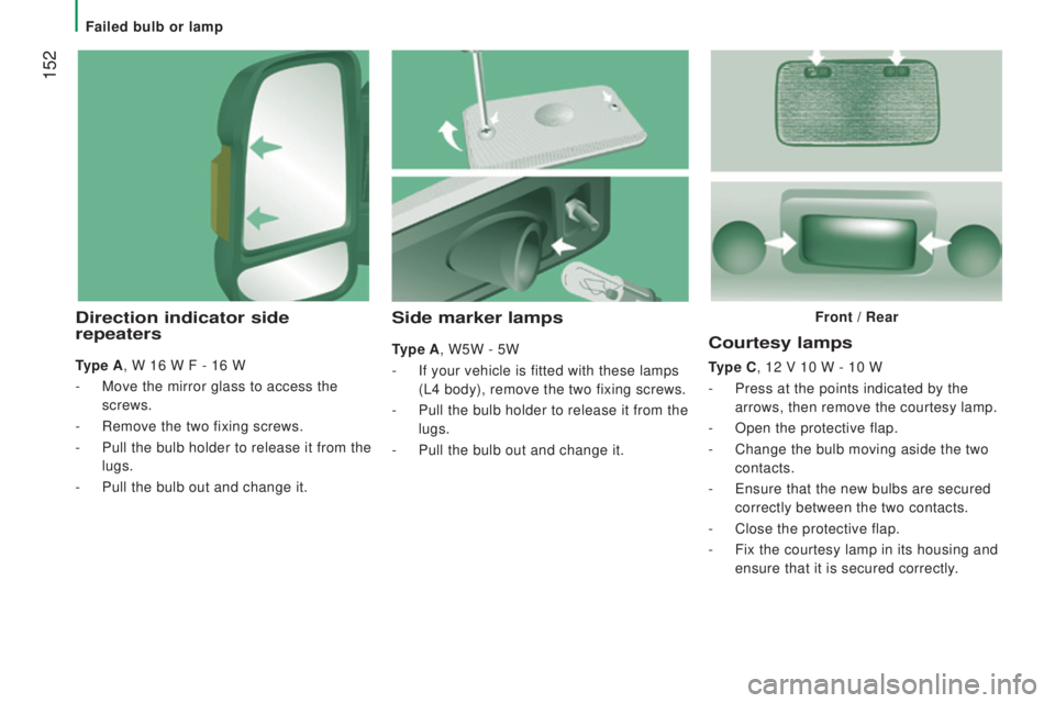
courtesy lamps
type c, 12 V 10 W - 10 W
-
Press at the points indicated by the
arrows, then remove the courtesy lamp.
-
Open the protective flap.
-
Change the bulb moving aside the two
contacts.
-
e
nsure that the new bulbs are secured
correctly between the two contacts.
-
Close the protective flap.
-
Fix the courtesy lamp in its housing and
ensure that it is secured correctly
.
Side marker lamps
type A, W5W - 5W
-
If your vehicle is fitted with these lamps
(L4 body), remove the two fixing screws.
-
Pull the bulb holder to release it from the
lugs.
-
Pull the bulb out and change it.
direction indicator side
repeaters
type A, W 16 W F - 16 W
-
Move the mirror glass to access the
screws.
-
Remove the two fixing screws.
-
Pull the bulb holder to release it from the
lugs.
-
Pull the bulb out and change it. Front /
rear
Failed bulb or lamp
Page 155 of 276
153
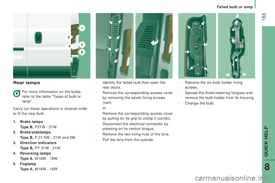
rear lamps
Carry out these operations in reverse order
to fit the new bulb.
1.
Brake lamps
type B, P21W - 21W
2.
Brake/sidelamps
type B, P
21/5W - 21W and 5W
3.
direction indicators
type B, PY
21W - 21W
4.
reversing lamps
type A, W16W - 16W
5.
Foglamp
type A, W16W - 16W -
Identify the failed bulb then open the
rear doors.
-
Remove the corresponding access cover
by removing the seven fixing screws
(van) or
Remove the corresponding access cover
by pulling on its grip to unclip it (combi).
-
Disconnect the electrical connector by
pressing on its central tongue.
-
Remove the two fixing nuts of the lens.
-
Pull the lens from the outside. -
Remove the six bulb holder fixing
screws.
-
Spread the three retaining tongues and
remove the bulb holder from its housing.
-
Change the bulb.
For more information on the bulbs,
refer to the table "
types of bulb or
lamp".
QuICK HeLP
8
Failed bulb or lamp
Page 156 of 276
154
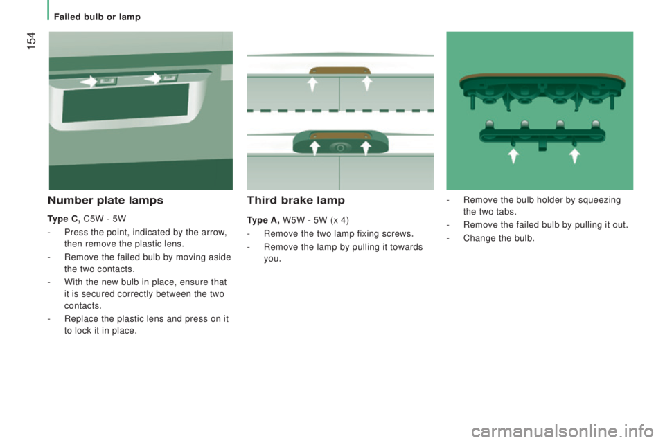
third brake lamp
type A, W5W - 5W (x 4)
-
Remove the two lamp fixing screws.
-
Remove the lamp by pulling it towards
you.
number plate lamps
type c, C5W - 5W
-
Press the point, indicated by the arrow,
then remove the plastic lens.
-
Remove the failed bulb by moving aside
the two contacts.
-
With the new bulb in place, ensure that
it is secured correctly between the two
contacts.
-
Replace the plastic lens and press on it
to lock it in place. -
Remove the bulb holder by squeezing
the two tabs.
-
Remove the failed bulb by pulling it out.
-
Change the bulb.
Failed bulb or lamp
Page 157 of 276
155
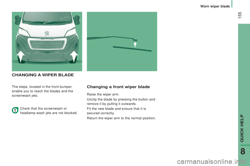
cHAnGInG A WIPEr BLAdE
the steps, located in the front bumper,
enable you to reach the blades and the
screenwash jets.changing a front wiper blade
Raise the wiper arm.
unclip the blade by pressing the button and
remove it by pulling it outwards.
Fit the new blade and ensure that it is
secured correctly.
Return the wiper arm to the normal position.
Check that the screenwash or
headlamp wash jets are not blocked.
QuICK HeLP
8
Worn wiper blade
Page 158 of 276
156
Parking the vehicle
Where possible, park the vehicle on level,
stable and non-slippery ground.
Apply the parking brake, switch off the
ignition and engage first gear.
Wear a high visibility vest and position the
warning triangle on the road.
You must ensure that the occupants get out
of the vehicle and wait in a safe location.
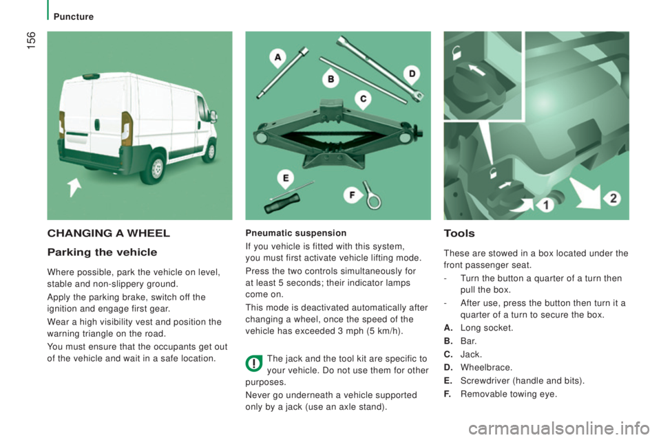
tools
these are stowed in a box located under the
front passenger seat.
-
t
urn the button a quarter of a turn then
pull the box.
-
After use, press the button then turn it a
quarter of a turn to secure the box.
A.
Long socket.
B.
Bar
.
c. Jack.
d. Wheelbrace.
E.
Screwdriver (handle and bits).
F.
Removable towing eye.
cHAnGInG A WHEELPneumatic suspension
If you vehicle is fitted with this system,
you must first activate vehicle lifting mode.
Press the two controls simultaneously for
at least 5 seconds; their indicator lamps
come on.
this mode is deactivated automatically after
changing a wheel, once the speed of the
vehicle has exceeded 3 mph (5 km/h).
the jack and the tool kit are specific to
your vehicle. Do not use them for other
purposes.
Never go underneath a vehicle supported
only by a jack (use an axle stand).
Puncture
Page 159 of 276
157
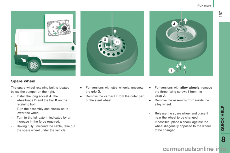
● For versions with alloy wheels, remove
the three fixing screws I from the
strap
j.
●
Remove the assembly from inside the
alloy wheel.
Spare wheel
the spare wheel retaining bolt is located
below the bumper on the right.
-
Install the long socket A , the
wheelbrace
d and the bar B on the
retaining bolt.
-
t
urn the assembly anti-clockwise to
lower the wheel.
-
t
urn to the full extent, indicated by an
increase in the force required.
-
Having fully unwound the cable, take out
the spare wheel under the vehicle. ●
For versions with steel wheels, unscrew
the grip
G.
●
Remove the carrier H from the outer part
of the steel wheel.
-
Release the spare wheel and place it
near the wheel to be changed.
-
If possible, place a chock against the
wheel diagonally opposed to the wheel
to be changed.
QuICK HeLP
8
Puncture
Page 160 of 276
158
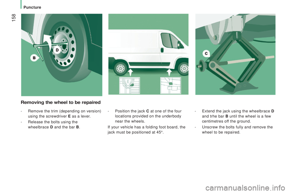
- extend the jack using the wheelbrace d
and trhe bar B until the wheel is a few
centimetres off the ground.
-
u
nscrew the bolts fully and remove the
wheel to be repaired.
- Position the jack c at one of the four
locations provided on the underbody
near the wheels.
If your vehicle has a folding foot board, the
jack must be positioned at 45°.
removing the wheel to be repaired
- Remove the trim (depending on version)
using the screwdriver E as a lever.
-
Release the bolts using the
wheelbrace
d and the bar B .
Puncture