bonnet PEUGEOT EXPERT 2022 Owners Manual
[x] Cancel search | Manufacturer: PEUGEOT, Model Year: 2022, Model line: EXPERT, Model: PEUGEOT EXPERT 2022Pages: 324, PDF Size: 10.39 MB
Page 5 of 324
3
Contents
Gear shift indicator 142
Automatic gearbox 142
Drive selector (Electric) 145
Driving modes (Electric) 146
Stop & Start 147
Tyre under-inflation detection 148
Driving and manoeuvring aids - General
recommendations
150
Head-up display 151
Memorising speeds 152
Road signs recognition 153
Speed limiter 155
Cruise control - Specific recommendations 157
Cruise control 157
Adaptive cruise control 160
Active Safety Brake with Collision Risk Alert and
Intelligent emergency braking assistance
163
Lane departure warning system 166
Distraction detection 167
Blind spot monitoring 168
Parking sensors 169
Visiopark 1 171
7Practical informationCompatibility of fuels 175
Refuelling 175
Diesel misfuel prevention 176
Charging system (Electric) 177
Charging the traction battery (Electric) 184
Energy economy mode 188
Snow chains 189
Towing device 189
Roof bars/Roof rack 190
Bonnet 191
Engine compartment 192
Checking levels 192
Checks 194
AdBlue® (BlueHDi) 196
Free-wheeling 198
Advice on care and maintenance 200
8In the event of a breakdownWarning triangle 202
Running out of fuel (Diesel) 202
Tool box 203
Temporary puncture repair kit 204
Spare wheel 207
Changing a bulb 2 11
Fuses 216
12
V battery
/ Accessory battery 216
Towing the vehicle 220
9Technical dataEngine technical data and towed loads 223
Diesel engines 224
Electric motor 229
Dimensions 231
Identification markings 233
10Bluetooth® audio systemFirst steps 235
Steering mounted controls 236
Menus 236
Radio 237
DAB (Digital Audio Broadcasting) radio 238
Media 239
Telephone 241
Frequently asked questions 244
11Audio System with Touch ScreenFirst steps 247
Steering mounted controls 248
Menus 249
Applications 250
Radio 250
DAB (Digital Audio Broadcasting) radio 252
Media 252
Telephone 254
Settings 257
Frequently asked questions 258
123D Connected NavigationFirst steps 260
Steering mounted controls 261
Menus 261
Voice commands 263
Navigation 266
Connected navigation 269
Applications 271
Radio 274
DAB (Digital Audio Broadcasting) radio 275
Media 275
Telephone 277
Settings 279
Frequently asked questions 281
13Event data recorders
■
Alphabetical index
■
Appendix
Page 6 of 324
4
Overview
Presentation
Instruments and controls
These illustrations and descriptions are intended
as a guide. The presence and location of some
components varies according to the version or
trim level.
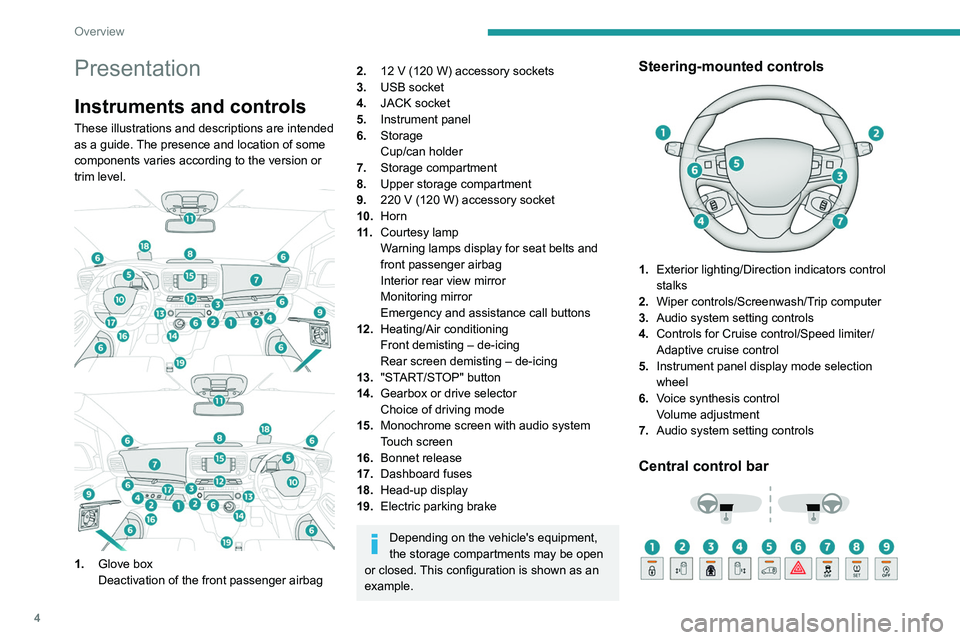
1.Glove box
Deactivation of the front passenger airbag
2.12 V (120 W) accessory sockets
3. USB socket
4. JACK socket
5. Instrument panel
6. Storage
Cup/can holder
7. Storage compartment
8. Upper storage compartment
9. 220
V (120 W) accessory socket
10.Horn
11
.Courtesy lamp
Warning lamps display for seat belts and
front passenger airbag
Interior rear view mirror
Monitoring mirror
Emergency and assistance call buttons
12. Heating/Air conditioning
Front demisting – de-icing
Rear screen demisting – de-icing
13. "START/STOP" button
14. Gearbox or drive selector
Choice of driving mode
15. Monochrome screen with audio system
Touch screen
16. Bonnet release
17. Dashboard fuses
18. Head-up display
19. Electric parking brake
Depending on the vehicle's equipment,
the storage compartments may be open
or closed. This configuration is shown as an
example.
Steering-mounted controls
1. Exterior lighting/Direction indicators control
stalks
2. Wiper controls/Screenwash/Trip computer
3. Audio system setting controls
4. Controls for Cruise control/Speed limiter/
Adaptive cruise control
5. Instrument panel display mode selection
wheel
6. Voice synthesis control
Volume adjustment
7. Audio system setting controls
Central control bar
Page 8 of 324
6
Overview
"Ease of use and comfort - Precautions for
seats and bench seats" section:
"Ease of use and comfort - Retractable
sliding table" section:
"Ease of use and comfort - Additional
heating/ventilation" section:
"Safety - Deactivating the front passenger
airbag" section:
"Safety - ISOFIX child seats" section:
"Safety - Manual child lock" section:
"Driving - Electric parking brake" section:
"Practical information - Compatibility of
fuels" section:
"Practical information - Charging system
(Electric)" section:
"Practical information - Charging the traction
battery (Electric)" section:
"Practical information - Bonnet" section:
"Practical information - Checking levels"
section:
"In the event of a breakdown - Spare wheel"
section:
"In the event of a breakdown - 12 V battery/
Accessory battery" section:
24V12V
Page 19 of 324
17
Dashboard instruments
1– an alert message indicates the distance
remaining, as well as the period before the next
service is due or how long it is overdue.
Service spannerOn temporarily when the ignition is
switched on.
Between 620 and 1,860 miles (1,000 and 3,000
km) remain before the next service is due.
Fixed, when the ignition is switched on.
The next service is due in less than 620
miles (1,000 km).
Have your vehicle serviced very soon.
Service spanner flashingFlashing then fixed, when the
ignition is switched on.
(With
BlueHDi Diesel engines, associated with
the Service warning lamp.)
The servicing interval has been exceeded.
Have your vehicle serviced as soon as possible.
Resetting the service indicator
The service indicator must be reset after each
service.
►
Switch the ignition off.
► Press and hold this button.
► Switch on the ignition; the distance recorder
display begins a countdown.
►
Release the button when =0
is displayed; the
spanner disappears.
If you have to disconnect the battery
following this operation, lock the vehicle
and wait at least 5 minutes for the reset to be
registered.
Retrieving the service information
The service information can be accessed at any
time.
►
Press this button.
The service information is displayed for a few
seconds, then disappears.
The distance indicated (in miles or kilometres) is calculated according to the
distance covered and the time elapsed since
the last service.
The alert may be triggered close to a due
date.
Coolant temperature
indicator (Diesel)
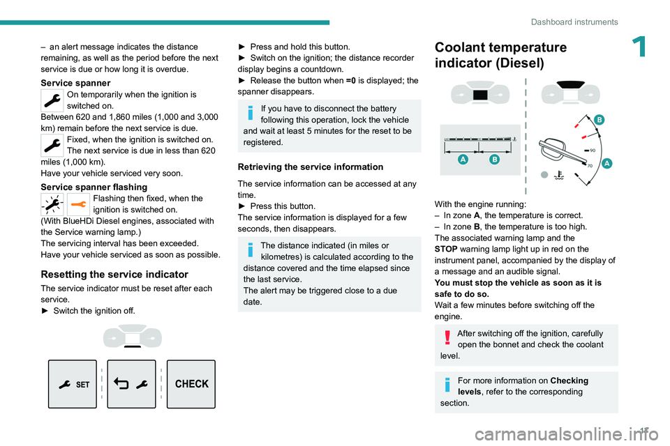
With the engine running:
– In zone A, the temperature is correct.
–
In zone
B, the temperature is too high.
The associated warning lamp and the
STOP
warning lamp light up in red on the
instrument panel, accompanied by the display of
a message and an audible signal.
You must stop the vehicle as soon as it is
safe to do so.
Wait a few minutes before switching off the
engine.
After switching off the ignition, carefully open the bonnet and check the coolant
level.
For more information on Checking
levels, refer to the corresponding
section.
Page 47 of 324
45
Access
2indicator lamps and in particular the door open
warning, refer to the corresponding section.
The tailgate and rear screen cannot both be open at the same time, to avoid
damaging them.
Alarm
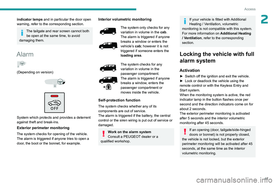
(Depending on version)
System which protects and provides a deterrent
against theft and break-ins.
Exterior perimeter monitoring
The system checks for opening of the vehicle.
The alarm is triggered if anyone tries to open a
door, the boot or the bonnet, for example.
Interior volumetric monitoring
The system only checks for any
variation in volume in the cab.
The alarm is triggered if anyone
breaks a window or enters the
vehicle’s cab; however it is not
triggered if someone enters the
loading area.
The system checks for any
variation in volume in the
passenger compartment.
The alarm is triggered if anyone
breaks a window, enters the
passenger compartment or
moves inside the vehicle.
Self-protection function
The system checks whether any of its
components are out of service.
The alarm is triggered if the battery, the central
control or the siren wiring is put out of service or
damaged.
Work on the alarm system
Consult a PEUGEOT dealer or a
qualified workshop.
If your vehicle is fitted with Additional
Heating / Ventilation, volumetric
monitoring is not compatible with this system.
For more information on Additional Heating
/ Ventilation , refer to the corresponding
section.
Locking the vehicle with full
alarm system
Activation
► Switch off the ignition and exit the vehicle.
► Lock or deadlock the vehicle using the
remote control or with the Keyless Entry and
Start system.
When the monitoring system is active, the red
indicator lamp in the button flashes once per
second and the direction indicators come on for
about 2 seconds.
The exterior perimeter monitoring is activated
after 5 seconds and the interior volumetric
monitoring after 45 seconds.
If an opening (door, tailgate/side-hinged
doors or bonnet) is not properly closed,
the vehicle is not locked, but the exterior
perimeter monitoring will be activated after 45
seconds, at the same time as the interior
volumetric monitoring.
Page 94 of 324
92
Lighting and visibility
– Vehicles whose lighting is obscured (for
example, vehicles driving behind a safety
barrier on a motorway).
–
V
ehicles at the top or bottom of a steep
slope, on winding roads, on crossroads.
Clean the windscreen regularly,
particularly the area in front of the
camera.
The internal surface of the windscreen can
also become misted around the camera.
In humid and cold weather, demist the
windscreen regularly.
Do not allow snow to accumulate on the
bonnet or roof of the vehicle as this could
obstruct the detection camera.
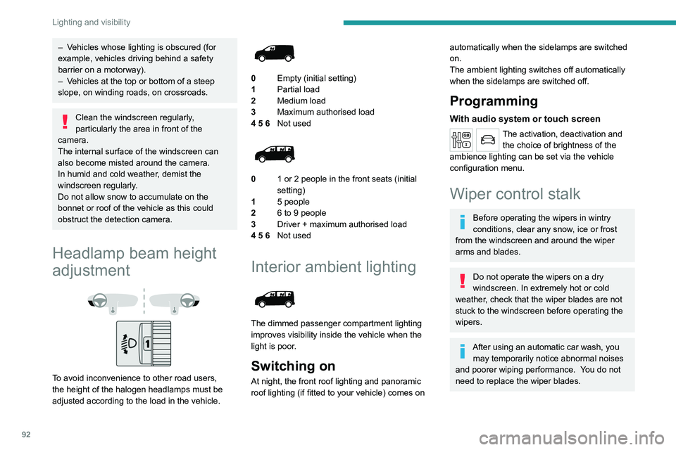
Headlamp beam height
adjustment
To avoid inconvenience to other road users,
the height of the halogen headlamps must be
adjusted according to the load in the vehicle.
0 Empty (initial setting)
1 Partial load
2 Medium load
3 Maximum authorised load
4 5 6 Not used
01 or 2 people in the front seats (initial
setting)
1 5 people
2 6 to 9 people
3 Driver + maximum authorised load
4 5 6 Not used
Interior ambient lighting
The dimmed passenger compartment lighting
improves visibility inside the vehicle when the
light is poor.
Switching on
At night, the front roof lighting and panoramic
roof lighting (if fitted to your vehicle) comes on
automatically when the sidelamps are switched
on.
The ambient lighting switches off automatically
when the sidelamps are switched off.
Programming
With audio system or touch screen
The activation, deactivation and
the choice of brightness of the
ambience lighting can be set via the vehicle
configuration menu.
Wiper control stalk
Before operating the wipers in wintry
conditions, clear any snow, ice or frost
from the windscreen and around the wiper
arms and blades.
Do not operate the wipers on a dry
windscreen. In extremely hot or cold
weather, check that the wiper blades are not
stuck to the windscreen before operating the
wipers.
After using an automatic car wash, you may temporarily notice abnormal noises
and poorer wiping performance.
You do not
need to replace the wiper blades.
Page 188 of 324
186
Practical information
For more information, contact a PEUGEOT
dealer or a qualified workshop.
During charging
While charging is in progress, unlocking
the vehicle will cause the charging to stop.
If no action is taken on one of the openings
(door or boot) or on the charging nozzle, the
vehicle will lock again after 30 seconds and
charging will resume automatically.
Never work under the bonnet:
–
Some areas remain very hot, even an hour
after charging ends - risk of burns!
–
The fan may start at any time - risk of cuts
or strangulation!
After charging
Check that the charging flap is closed.
Do not leave the cable connected to the
domestic power socket - risk of short-circuit
or electrocution in the event of contact with or
immersion in water!
For superfast charging
Before charging
Check that the fast public charging
station and its charging cable are compatible
with the vehicle.
If the exterior temperature is below:
–
0°C, charging times may be extended.
– -20°C, charging is still possible, but
charging times may be extended even further
(the battery has to be heated first).
After charging
Check that the charging flap is closed.
Connection
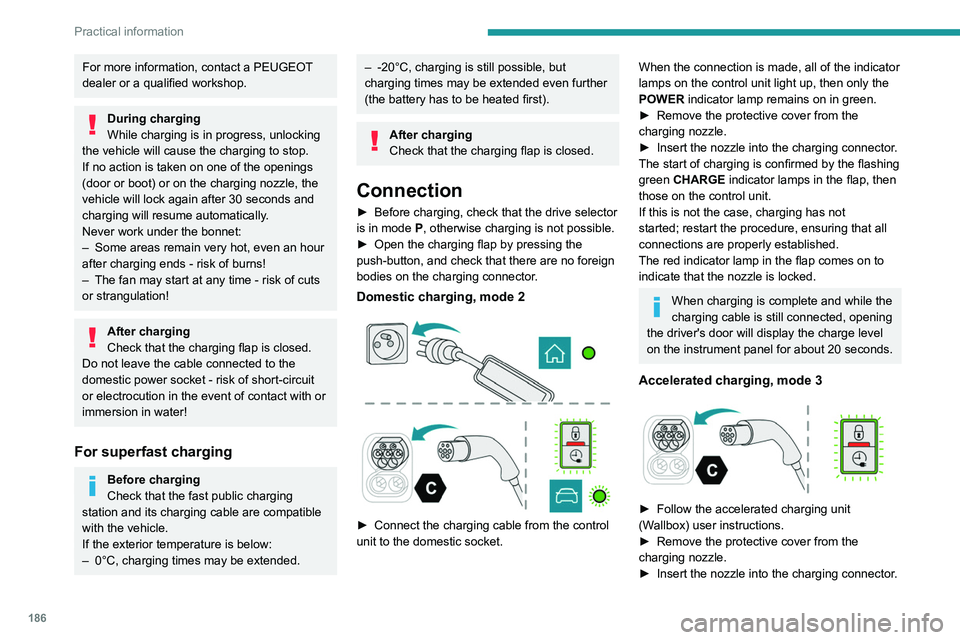
► Before charging, check that the drive selector
is in mode P, otherwise charging is not possible.
►
Open the charging flap by pressing the
push-button, and check that there are no foreign
bodies on the charging connector
.
Domestic charging, mode 2
► Connect the charging cable from the control
unit to the domestic socket.
When the connection is made, all of the indicator
lamps on the control unit light up, then only the
POWER indicator lamp remains on in green.
►
Remove the protective cover from the
charging nozzle.
►
Insert the nozzle into the charging connector
.
The start of charging is confirmed by the flashing
green CHARGE indicator lamps in the flap, then
those on the control unit.
If this is not the case, charging has not
started; restart the procedure, ensuring that all
connections are properly established.
The red indicator lamp in the flap comes on to
indicate that the nozzle is locked.
When charging is complete and while the
charging cable is still connected, opening
the driver's door will display the charge level
on the instrument panel for about 20 seconds.
Accelerated charging, mode 3
► Follow the accelerated charging unit
(W allbox) user instructions.
►
Remove the protective cover from the
charging nozzle.
►
Insert the nozzle into the charging connector
.
Page 193 of 324
191
Practical information
7Roof racks
Max. authorised load weight:
– Compact: 140 kg,
–
Standard and Long: 170 kg.
T
o fit a roof rack, use the fixing points provided
for this purpose:
►
Place the roof rack on the roof aligned with
the fixing points and secure each one to the roof
in turn.
►
Ensure that the roof rack is correctly fitted (by
shaking it).
Bonnet
Stop & Start
Before doing anything under the bonnet,
you must switch off the ignition to avoid any
risk of the engine restarting automatically.
Take care with objects or clothing that could
be caught in the blades of the cooling fan
or in certain moving components - risk of
strangulation and serious injury!
Electric motor
Take care with objects or clothing that
could be caught in the blades of the cooling
fan or in certain moving components - risk of
strangulation and serious injury!
Before carrying out any work under the
bonnet, you must switch off the ignition, check
that the READY indicator lamp is off on the
instrument panel and disconnect the nozzle
from the charging connector if it is connected.
The location of the interior bonnet release lever prevents the bonnet being
opened when the left-hand front door is
closed.
When the engine is hot, handle the
exterior safety catch and the bonnet stay
with care (risk of burns), using the protected
area.
When the bonnet is open, take care not to
damage the safety catch.
Do not open the bonnet under very windy
conditions.
Cooling of the engine when stopped
The engine cooling fan may start after
the engine has been switched off.
Take care with objects or clothing that
could be caught in the blades of the fan!
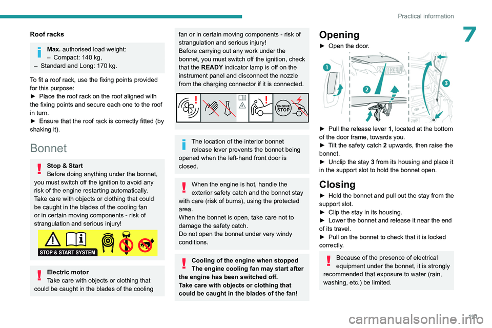
Opening
► Open the door .
► Pull the release lever 1 , located at the bottom
of the door frame, towards you.
►
T
ilt the safety catch 2 upwards, then raise the
bonnet.
►
Unclip the stay
3 from its housing and place it
in the support slot to hold the bonnet open.
Closing
► Hold the bonnet and pull out the stay from the
support slot.
►
Clip the stay in its housing.
►
Lower the bonnet and release it near the end
of its travel.
►
Pull on the bonnet to check that it is locked
correctly
.
Because of the presence of electrical
equipment under the bonnet, it is strongly
recommended that exposure to water (rain,
washing, etc.) be limited.
Page 194 of 324
192
Practical information
Engine compartment
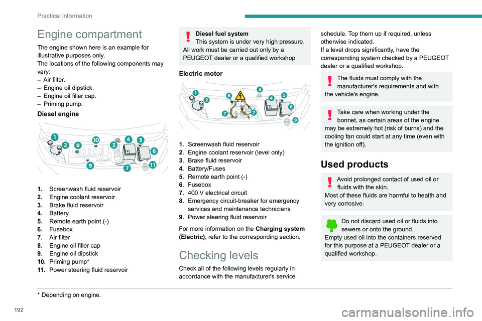
The engine shown here is an example for
illustrative purposes only.
The locations of the following components may
vary:
–
Air filter
.
–
Engine oil dipstick.
–
Engine oil filler cap.
–
Priming pump.
Diesel engine
1. Screenwash fluid reservoir
2. Engine coolant reservoir
3. Brake fluid reservoir
4. Battery
5. Remote earth point (-)
6. Fusebox
7. Air filter
8. Engine oil filler cap
9. Engine oil dipstick
10. Priming pump*
11 . Power steering fluid reservoir
* Depending on engine.
Diesel fuel system
This system is under very high pressure.
All work must be carried out only by a
PEUGEOT dealer or a qualified workshop
Electric motor
1. Screenwash fluid reservoir
2. Engine coolant reservoir (level only)
3. Brake fluid reservoir
4. Battery/Fuses
5. Remote earth point (-)
6. Fusebox
7. 400
V electrical circuit
8. Emergency circuit-breaker for emergency
services and maintenance technicians
9. Power steering fluid reservoir
For more information on the Charging system
(Electric), refer to the corresponding section.
Checking levels
Check all of the following levels regularly in
accordance with the manufacturer's service
schedule. Top them up if required, unless
otherwise indicated.
If a level drops significantly, have the
corresponding system checked by a PEUGEOT
dealer or a qualified workshop.
The fluids must comply with the manufacturer's requirements and with
the vehicle's engine.
Take care when working under the bonnet, as certain areas of the engine
may be extremely hot (risk of burns) and the
cooling fan could start at any time (even with
the ignition off).
Used products
Avoid prolonged contact of used oil or fluids with the skin.
Most of these fluids are harmful to health and
very corrosive.
Do not discard used oil or fluids into
sewers or onto the ground.
Empty used oil into the containers reserved
for this purpose at a PEUGEOT dealer or a
qualified workshop.
Page 204 of 324
202
In the event of a breakdown
Warning triangle
This reflective and dismantlable device is to be
installed on the side of the road when a vehicle
is broken down or damaged.
Before getting out of the vehicle
Turn on the hazard warning lamps, then
put on the safety vest to assemble and install
the triangle.
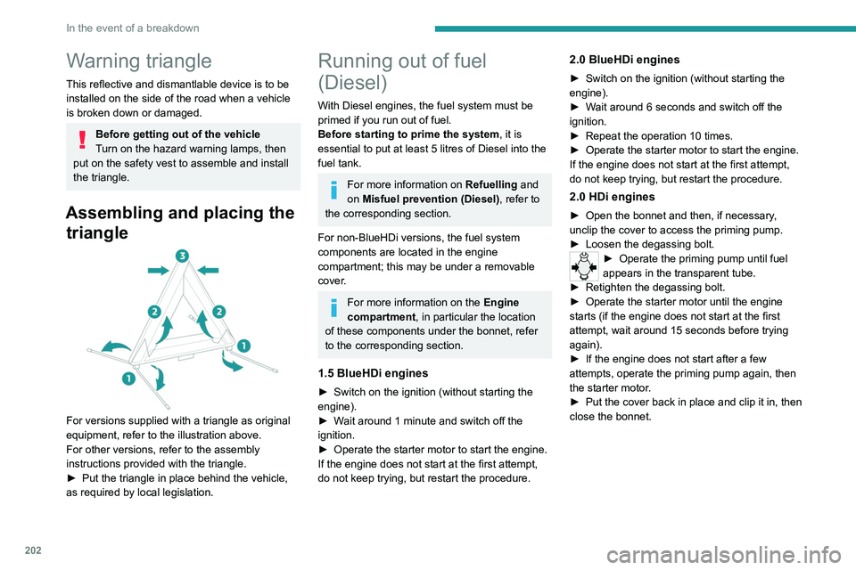
Assembling and placing the triangle
For versions supplied with a triangle as original
equipment, refer to the illustration above.
For other versions, refer to the assembly
instructions provided with the triangle.
►
Put the triangle in place behind the vehicle,
as required by local legislation.
Running out of fuel
(Diesel)
With Diesel engines, the fuel system must be
primed if you run out of fuel.
Before starting to prime the system, it is
essential to put at least 5 litres of Diesel into the
fuel tank.
For more information on Refuelling and
on Misfuel prevention (Diesel), refer to
the corresponding section.
For non-BlueHDi versions, the fuel system
components are located in the engine
compartment; this may be under a removable
cover.
For more information on the Engine
compartment, in particular the location
of these components under the bonnet, refer
to the corresponding section.
1.5 BlueHDi engines
► Switch on the ignition (without starting the
engine).
►
W
ait around 1 minute and switch off the
ignition.
►
Operate the starter motor to start the engine.
If the engine does not start at the first attempt,
do not keep trying, but restart the procedure.
2.0 BlueHDi engines
► Switch on the ignition (without starting the
engine).
►
W
ait around 6 seconds and switch off the
ignition.
►
Repeat the operation 10
times.
►
Operate the starter motor to start the engine.
If the engine does not start at the first attempt,
do not keep trying, but restart the procedure.
2.0 HDi engines
► Open the bonnet and then, if necessary ,
unclip the cover to access the priming pump.
►
Loosen the degassing bolt.
► Operate the priming pump until fuel
appears in the transparent tube.
►
Retighten the degassing bolt.
►
Operate the starter motor until the engine
starts (if the engine does not start at the first
attempt, wait around 15
seconds before trying
again).
►
If the engine does not start after a few
attempts, operate the priming pump again, then
the starter motor
.
►
Put the cover back in place and clip it in, then
close the bonnet.