fuse PONTIAC BONNEVILLE 2003 Owners Manual
[x] Cancel search | Manufacturer: PONTIAC, Model Year: 2003, Model line: BONNEVILLE, Model: PONTIAC BONNEVILLE 2003Pages: 418, PDF Size: 20.24 MB
Page 9 of 418
Front Seats Power Seats
Manual Seats
You can lose control of the vehicle if you try to
adjust
a manual driver’s seat while the vehicle
is moving. The sudden movement could startle
and confuse you, or make you push a pedal when you don’t want to. Adjust the driver’s
seat only when the vehicle is not moving.
Pull up on the control bar located under the front of the
seat to unlock it. Slide the seat to where you want it
and release the bar.
Try to move the seat with your body
to make sure the seat is locked into place. If
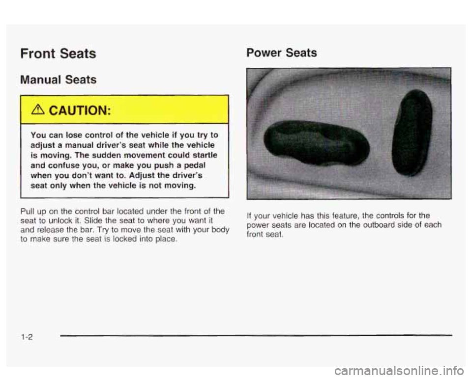
your vehicle has this feature, the controls for
the
power seats are located on the outboard side of each
front seat.
1-2
Page 87 of 418
Testing the Alarm
1. From inside the vehicle, roll down the window.
2. Activate the system by locking the doors with the
power door lock switch while the door is open, or
with the remote keyless entry transmitter.
3. Get out of the vehicle, close the door and wait for
the SECURITY light to go out.
4. Then, reach in through the window, unlock the door
with the manual door lock and open the door. This
should set
off the alarm.
If the alarm does not sound when it should, check to
see
if the horn works. The horn fuse may be blown.
To replace the fuse, see
Fuses and Circuit Breakers on
page 5-92.
If the alarm does not sound, or the exterior lamps do
not flash, see your dealer.
Content Theft-Deterrent
If your vehicle has this option, it has a content
theft-deterrent alarm system.
A light located in your Twilight Sentinel@ cluster, above
the fog lamp button, will begin to flash
30 seconds
after the vehicle ignition is turned
off to let you know the
system has been armed.
While armed, the doors will not unlock with the power
door lock switch. Once armed,
the alarm will go
off if someone tries to
enter the vehicle without using the remote keyless entry
transmitter or a key, breaks a window, tries to damage
the vehicle or turns the ignition to
ON. If any of these do
occur, the horn will sound and the parking lamps will
flash for up to two minutes.
PASS-Key@ 111
Your PASS-Key@ Ill system operates on a radio
frequency subject to Federal Communications
Commission (FCC) Rules and with Industry Canada.
This device complies with Part
15 of the FCC Rules.
Operation is subject to the following two conditions:
(1)
this device may not cause harmful interference, and
(2) this device must accept any interference received,
including interference that may cause undesired
operation.
This device complies with RSS-210 of Industry Canada
Operation is subject to the following two conditions:
(1) this device may not cause interference, and (2) this
device must accept any interference received,
including interference that may cause undesired
operation of the device.
Changes
or modifications to this system by other than
an authorized service facility could void authorization to
use this equipment.
PASS-Key@
Ill uses a radio frequency transponder in
the key that matches
a decoder in your vehicle.
2-22
Page 88 of 418
PASS-Key@ 111 Operation
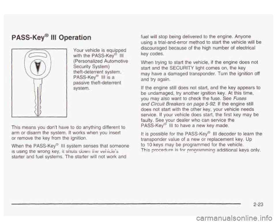
Your vehicle is equipped
with the PASS-Key@
Ill
(Personalized Automotive
Security System)
theft-deterrent system.
PASS-Key@
I II is a
passive theft-deterrent
system.
This means you don’t have
to do anything different to
arm or disarm the system. It works when you insert
or remove the key from the ignition.
When the PASS-Key@
Ill system senses that someone
IS using tne wrong key, ii snuis civwrl iile veilide’s
starter and fuel systems. The starter will not work and fuel will stop being delivered to the
engine. Anyone
using a trial-and-error method to start the vehicle will be
discouraged because of the high number
of electrical
key codes.
When trying to start the vehicle,
if the engine does not
start and the SECURITY light comes on, the key
may have a damaged transponder. Turn the ignition
off
and try again.
If the engine
still does not start, and the key appears to
be undamaged, try another ignition key. At this time,
you may also want to check the fuse. See
Fuses
and Circuit Breakers on page 5-92. If the engine still
does not start with the other key, your vehicle needs
service.
ii your vehicle does star?, the first key ~ay be
faulty. See your dealer who can service the
PASS-Key@
Ill to have a new key made.
It is possible for the PASS-Key@ Ill decoder to learn the
transponder value of a new or replacement key. Up
to
10 keys may be programmed for the vehicle.
Thls prccerll-!re is fnr programming additional keys only.
2-23
Page 122 of 418
Turn Signal/Nlultifunction Lever
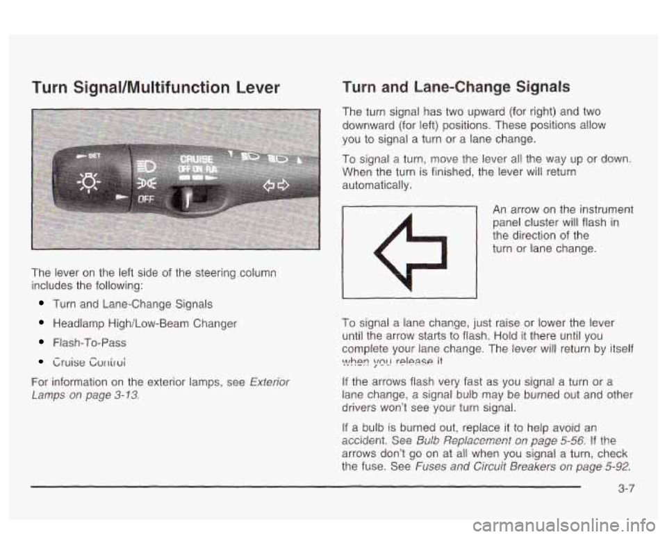
The lever on the left side of the steering column
includes the following:
Turn and Lane-Change Signals
Headlamp High/Low-Beam Changer
Flash-To-Pass
Cruise Cvrriroi
For information on the exterior lamps, see Exterior
Lamps
on page 3-13.
Turn and Lane-Change Signals
The turn signal has two upward (for right) and two
downward (for left) positions. These positions allow
you
to signal a turn or a lane change.
To signal a turn, move the lever all the way up or down.
When the turn is finished, the lever will return
automatically.
- An arrow on the instrument
panel cluster will flash in
the direction of the
turn or lane change.
I
To signal a lane change, just raise or lower the lever
until the arrow starts to flash. Hold
it there until you
complete your lane change. The lever will return by itself
If the arrows flash very fast as you signal a turn or a
lane change, a signal bulb may be burned out and other
drivers won’t see your turn signal.
If a bulb is burned out, replace it to help avoid an
accidmt. See &Ab ,%?pfaxment s,~ page 5-56 !? the
arrows don’t go on at all when you signal a turn, check
the fuse. See
Fuses and Circuit Breakers on page 5-92.
\>!hen ;mL! rplpase it
3-7
Page 138 of 418
If you can’t see the HUD image when the ignition is on,
check to see
if:
0 The HUD unit is covered,
0 the HUD INTENSITY knob is adjusted correctly,
0 the HUD image is adjusted to the proper height, or
a fuse in the fuse panel may have blown. See
Fuses and Circuit Breakers on page 5-92.
If the HUD image is not clear, it could be too bright.
Move the HUD INTENSITY knob counterclockwise. You
may need to clean the windshield and HUD lens.
Your windshield is part of the HUD system. If you ever
have to have a new windshield, be sure to get one
designed for HUD.
If you don’t, the HUD image may look
blurred and out of focus.
Accessory Power Outlets
If your vehicle has a front console, the accessory power
outlet
(1 2-volt ) is located at the rear of the front
console.
If your vehicle has a floor console, the outlet is
located at the rear of the floor console. To
use the outlet, remove the protective cap which
covers it. When not using it, always cover the outlet with
the protective cap.
The accessory power outlet will only operate when the
ignition key
is in ON and for 10 minutes after turning
the ignition OFF. If you would like the accessory power
outlet to operate regardless of ignition position, and
for extended periods of time, see “Engine Compartment
Fuse
Block” under Fuses and Circuit Breakers on
page 5-92 or see your dealer for more information.
Nofice: When using an accessory power outlet,
maximum electrical load must not exceed
15 amps.
Always turn
off any electrical equipment when
not in use. Leaving electrical equipment on for
extended periods will drain your battery.
Certain electrical accessories may not be compatible
with the accessory power outlet and could result
in blown vehicle or adapter fuses.
If you experience a
problem, see your dealer for additional information
on accessory power outlets.
3-23
Page 139 of 418
Notice: Adding some electrical equipment to your
vehicle can damage
it or keep other things from
working as they should. This wouldn’t be covered by
your warranty. Check with your dealer before adding electrical equipment, and never use anything
that exceeds the amperage rating.
When adding electrical equipment, be sure to follow the
proper installation instructions included with the
equipment.
Notice: Power outlets are designed for accessory
plugs only.
Do not hang any type of accessory
or accessory bracket from the plug. Improper use of
the power outlet can cause damage not covered
by your warranty.
Ashtrays and Cigarette Lighter
Push down on the cover to reveal the front ashtray.
To clean the ashtray,
lift it out by pulling on the finger
holes on each side.
On models without a console, an ashtray is located
underneath the instrument panel.
To clean the ashtray,
lift it out by pulling up on the tabs on either side.
It snaps back into place.
To open a rear ashtray, lift the cover
Notice: Don’t put papers or other flammable
items into your ashtrays. Hot cigarettes or other
smoking materials could ignite them, causing
a damaging fire.
The cigarette lighter is located next to the storage tray.
To use a lighter, just push the center in all the way
and let
it go. When it is ready, the center will pop back
out by itself. Pull out the entire unit to use it.
Notice: Don’t hold a cigarette lighter in with your
hand while
it is heating. If you do, it won’t be able to
back away from the heating element when it’s
ready. That can make
it overheat, damaging the
lighter and the heating element.
The cigarette lighter will only operate when the ignition
key is in
ON and for 10 minutes after turning the
ignition
OFF. If you would like the lighter to operate
regardless of ignition position, and for extended periods
of time, see “Engine Compartment Fuse Block under
Fuses and Circuit Breakers on page 5-92 or see
your dealer.
3-24
Page 173 of 418
TRIP RESET: This button allows you to reset your trip
odometer. To reset the trip odometer, press the
TRIP RESET button. The trip odometer will now
accumulate miles (kilometers) until the next reset.
MODE: This button allows you to toggle through the
DIC modes (Vehicle Data, Personalization Programming,
Compass Calibration).
SELECT: This button allows you to select a DIC mode.
RESET: This button, when used along with other
buttons, will allow you
to reset system functions.
Vehicle Data
Average Fuel Economy: Press the SELECT button
until the display shows AVG FUEL ECONOMY. Average
fuel economy is viewed as a long term approximation
of your overall driving conditions. To learn the average
fuel economy from a new starting point, press the
RESET button for five seconds while the average fuel
economy is displayed on the DIC.
Instantaneous Fuel Economy: Press the SELECT
button until the display shows INST FUEL ECONOMY.
Instantaneous fuel economy varies with your driving
conditions, such as acceleration, braking and the grade
of the road being traveled. The RESET button does
not function in this mode.
Fuel Range: Press the SELECT button until the display
shows FUEL RANGE. The fuel range will calculate
the remaining distance you can drive without refueling.
This calculation is based on the average fuel economy
for the last
25 miles (40.25 km) driven, and the fuel
remaining in the fuel tank. If the fuel range drops below
40 miles (64.4 km), the display will show FUEL
RANGE LOW. The RESET button does not function in
this mode.
Fuel Used: Press the SELECT button until the display
shows FUEL USED. The value indicates how much
fuel has been used since the last reset. Don’t confuse
fuel used with the amount of fuel in your tank. To
learn how much fuel
will be used from a specific starting
point, press
the RESET button for five seconds while
the fuel used is displayed on the DIC.
3-58
Page 261 of 418
Section 5 Service and Appearance Care
Windshield Wiper Blade Replacement ............. 5-61
Tires .............................................................. 5.62
Inflation
.. Tire Pressure ................................ 5.62
Check Tire Pressure System
.......................... 5.64
Tire Inspection and Rotation
........................... 5.65
When It
Is Time for New Tires ....................... 5-67
Buying New Tires
........................................ 5-67
Uniform Tire Quality Grading
.......................... 5.68
Wheel Replacement
...................................... 5.69
Tire Chains
.................................................. 5-71
Accessory Inflator
......................................... 5.72
If a Tire Goes Flat ........................................ 5.72
Changing a Flat Tire
..................................... 5.73
Compact Spare Tire
..................................... 5-81
Appearance Care ............................................ 5.82
Wheel
Alignment and Tire Balance
.................. 5-69
Cleaning the Inside of Your Vehicle
................. 5-82
Care of Safety Belts
...................................... 5-85
Weatherstrips ............................................... 5.85
Cleaning the Outside of Your Vehicle .............. 5-85
Sheet Metal Damage
..................................... 5.87
Finish Damage
............................................. 5.87
Underbody Maintenance
................... ...... 5.87
Chemical Paint Spotting
................................. 5.88
Vehicle Identification ..................................... 5-90
Vehicle Identification Number (VIN)
...... ., ...... 5-90
Service Parts Identification Label
........ ...... 5-90
Electrical System ............................... ...... 5-91
Add-on Electrical Equipment
................ , ...... 5-91
Headlamp Wiring
.......................................... 5-91
Windshield Wiper Fuses
................................ 5-91
Power Windows and Other Power Options
....... 5-91
Fuses and Circuit Breakers
............................ 5-92
Removing the Rear Seat Cushion
................... 5-95
Capacities and Specifications ........................ 5-100
Normal Maintenance Replacement Parts ......... 5-101
GM Vehicle Care/Appearance Materials .......... 5.88
5-2
Page 263 of 418
You can be injured and your vehicle could be damaged if you try to do service work on a
vehicle without knowing enough about
it.
Be sure you have sufficient knowledge,
experience, the proper replacement parts
and tools before you attempt any vehicle maintenance task.
Be sure to use the proper nuts, bolts and
other fasteners. “English” and “metric”
fasteners can be easily confused.
If you
use the wrong fasteners, parts can later
break or fall
off. You could be hurt.
Adding Equipment to the Outside of
Your Vehicle
Things you might add to the outside of your vehicle can
affect the airflow around it. This may cause wind
noise and affect windshield washer performance. Check
with your dealer before adding equipment to the
outside of your vehicle.
5-4
Page 274 of 418
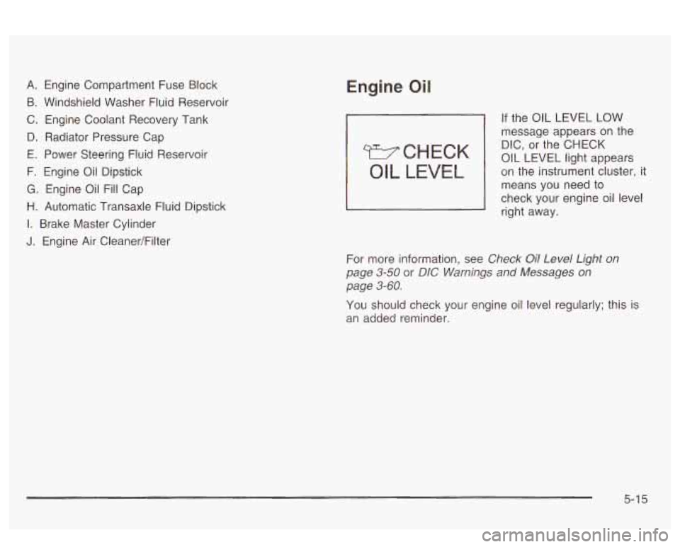
A. Engine Compartment Fuse Block
B. Windshield Washer Fluid Reservoir
C. Engine Coolant Recovery Tank
D. Radiator Pressure Cap
E. Power Steering Fluid Reservoir
F. Engine Oil Dipstick
G. Engine Oil Fill Cap
H. Automatic Transaxle Fluid Dipstick
I. Brake Master Cylinder
J. Engine Air Cleaner/Filter
Engine Oil
WCHECK
OIL LEVEL
If the OIL LEVEL LOW
message appears
on the
DIC, or the CHECK
OIL LEVEL light appears
on the instrument cluster, it
means
YOU need to
check your engine oil level
right away.
For more information, see
Check Oil Level Light on
page
3-50 or DIG Warnings and Messages on
page 3-60.
You should check your engine oil level regularly; this is
an added reminder.
5-1 5