lights PONTIAC FIERO 1988 Service Repair Manual
[x] Cancel search | Manufacturer: PONTIAC, Model Year: 1988, Model line: FIERO, Model: PONTIAC FIERO 1988Pages: 1825, PDF Size: 99.44 MB
Page 1601 of 1825
88-2 LIGHTING SYSTEMS AND HORNS
The fog lights must be aimed for proper
illumination of the road. Fog light
aim should be
checked: at least once a year; when a new light housing
is installed; or if service or repairs in the front end area
have (or may have) disturbed the fog light mountings.
FRONT PARKING/TURM SIGNAL
LIGHTS - Pushing either side of the instrument panel
switch will turn on the front parking lights. (Pushing
the left side of the switch will also turn on the
headlights.) When the ignition is on and the turn signal
lever is moved, the appropriate front parking light
flashes to signal a turn. Both lights will flash when the
hazard flashers are on.
If the driver's door is opened when the parking
lights are on, a warning tone will sound. For more
information, see Section
8A-77.
HAZARD FLASHERS - The hazard warning
flasher is part of the turn signal circuit. Pushing in the
button (on the right side of the steering column) will
cause the front and rear turn signal lights, and the front
sidemarker lights, to flash. Pull out the collar around
the button to turn off the hazard flashers.
The hazard flashers will work with the ignition
either off or on. When the hazard flashers are on, the
turn signals do not
work.
The hazard flashers will stop flashing and stay on
brightly if the brake pedal is pushed down.
HEADLIGHTS - The headlights are controlled
by the switch on the instrument panel (to the left of the
speedometer). They will come on whether or not the
ignition is turned on. Pushing the upper left side of the
switch turns on the headlights and causes the headlight
motors to raise the headlights. Pushing the bottom part
of the switch turns off the headlights, and they should
lower.
If the driver's door is opened when the ignition
is off and the headlights are on, a warning tone will
sound. For more information, see Section
8A-77.
Headlight low-beam and high-beam are
controlled by the turn
signal/multifunction lever on
the left side of the steering column. When the
headlights are on, pull the lever toward the steering
wheel until the switch clicks; the lights will change
from low-beam to high-beam, or from high-beam to
low-beam. An indicator light on the center instrument
cluster will come on when the high-beam headlights
are on.
The headlights must be aimed for proper
illumination of the road. Headlight aim should be
checked: at least once a year; when a new headlight
bulb is installed; or if service or repairs in the front end
area have (or may have) disturbed the headlights or
their mountings. The headlight bezels do not need to
be removed to aim the headlights.
Headlight focus is set when the sealed-beam unit
is made; no adjustment for focus is necessary or
possible.
Some state and local laws specify
requirements for headlight aim; these laws
must be followed.
LICENSE PLATE LBGHTS -A light above the
rear license plate will come on when the headlights or
parking lights are on.
LIGHT SWITCH - Most exterior lights are
controlled by the switch on the instrument panel, to the
left of the speedometer. Pushing the upper right part
of the switch turns on the front parking lights, the
taillights and the sidemarker lights. (It also turns on
the instrument panel lights.) Pushing the upper left
part of the switch turns on all these lights plus the
headlights. Pushing the bottom part of the switch turns
off all lights.
In some cases (such as going through a car wash),
it may be desirable to raise the headlights without
leaving the headlights on. To do so, push the upper
right part of the switch to turn on the parking lights.
Then, lightly push the upper right part of the switch;
the headlights will raise but will not turn on.
(Remember that the parking lights and taillights will
stay on.)
For more information on this switch (including
on-car service), see Section
8C. Also see Section 8C for
information on interior lights.
REAR TAlL/STOP/TURN SIGNAL
LIGHTS - The rear tail/stop/turn signal lights are
part of the same light assembly. Pushing either side of
the instrument panel switch turns on the taillights.
When the brake pedal is pushed down, the lights glow
brighter to serve as stoplights.
Moving the turn signal lever when the ignition is
on causes the appropriate rear lights to flash. (If the
brake pedal is held down and a turn is signalled, one
side will flash and the other will stay on brightly.)
All lights will flash when the hazard flashers are
on. However, if the brake pedal is pushed while the
hazard flashers are on, the lights will stop flashing and
stay on brightly.
SIDEMARKER LIGHTS -The front and rear
sidemarker lights will come on when the headlights or
parking lights are on. Both front and rear sidemarker
lights also have reflectors; they will shine when struck
by light, whether or not the car's lights are on.
If the headlights or parking lights are off when a
turn is signalled, the front sidemarker light will flash
in unison with the front turn signal light on the same
side. If the lights are on when a turn is signalled, the
front
sidemarker light and front turn signal light flash
alternately.
TURN SlG N ALS - The front turn signals are
combined with the front parking lights. The rear turn
signals are part of the rear
tail/stop/turn signal lights.
The turn signals work only when the ignition is on, and
the hazard flashers are turned off.
The turn signals are controlled by the turn
signal/multifunction lever on the left side of the
steering column. Moving the lever all the way up or
down (past the detent) will turn on the turn signals.
When the turn is completed, the lever will return to
neutral and the turn signals will stop flashing.
For changing lanes or shallow turns where the
steering wheel does not move far enough to cancel the
signal, move the turn signal lever only to the first
detent. When the lever is released, it will return to
neutral and the turn signals will cancel.
UNDERHOOD LIGHT - The underhood light
will come on when the hood is raised.
Page 1602 of 1825
LIGHTING SYSTEMS AND HORNS 8B-3
HORNS the steering wheel sounds the horn by closing the horn
relay (in the convenience center behind the instrument
panel, to the right of the steering column). The horns
The holm(§) are mounted behind the front fascia use a solenoid-operated diaphragm to generate sound.
on the driver's side. $ushing the pad in the center of See Section 8A-40 for wiring and circuit information.
ON-CAR SERVICE
Wiring diagrams and other diagnosis information
is given in Section
8A. Information on properly
repairing wiring harnesses, connectors, etc., is on
8A-5.
Most lighting problems are caused by loose
connectors, open or shorted wiring, burned-out bulbs,
bad switches, inadequate ground or blown fuses. Many
of these require only replacement of a defective part.
When replacing a part that requires a special procedure
(such as a lens and housing assembly sealed together),
follow the instructions normally included in the
replacement parts package.
When removing a part that requires special
sealing items (such as sealing washers), be sure to
reinstall those items when replacing the part. Also, if
any body sealing items (grommets, etc.) are disturbed,
be sure to repair them so the passenger compartment
remains properly sealed.
EXTERlOR LIGHTS
BACK-UP LIGHTS
Fig. 8B-8
Replacement Bulb: Trade No. 1156, 32
Candlepower
To replace a back-up light bulb, see "Rear
Tail/Stop/Turn Signal Lights9' in this section. For
information on the back-up light switch on the
transmission, see Section
7.
CENTER HIGH-MOUNTED STOPLIGHT
Fig. 8B-7
Assembly Replacement
Remove or Disconnect
1. Spoiler (see Body Service Manual, Section 7H)
2. Four nuts from assembly
3. Stoplight assembly
Install or Connect
1. Stoplight assembly
2. Four nuts
3. Spoiler
Bulb Replacement
Replacement Bulb: Trade No. 577, 21
Candlepo wer
Remove or Disconnect
1. Two screws from lens
2. Lens
3. Bulb from socket
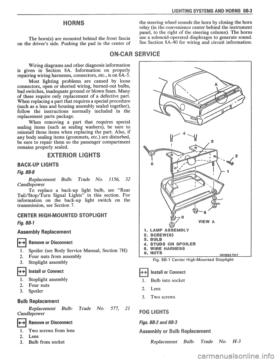
1. LAMP ASSEMBLY
2. SCREW($) 3. BULB
4. STUD8 ON SPOILER 5. WIRE HARNESS
Fig. 8B-1 Center High-Mounted Stoplight
Install or Corrnect
1. Bulb into socket
2. Lens
3. Two screws
FOG LIGHTS
Figs. 8B-2 and 88-3
Assembly or Bulb Replacement
Replacement Bulb: Trade No. H-3
Page 1603 of 1825
8B-4 LIGHTING SYSTEMS AND HORNS
Remove or Disconnect
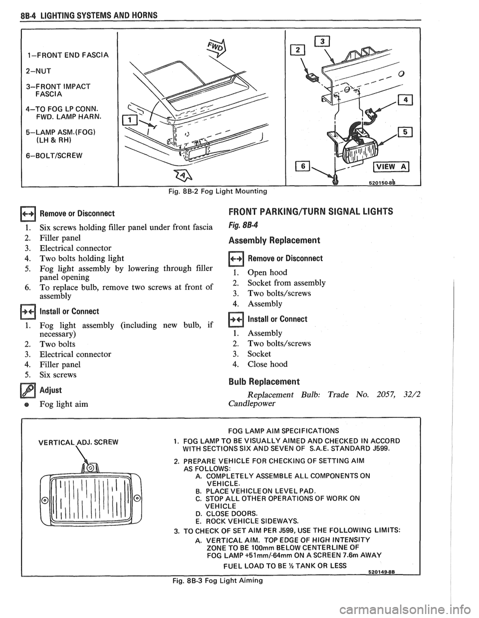
Six screws holding filler panel under front fascia
Filler panel
Electrical connector
Two bolts holding light
Fog light assembly by lowering through filler
panel opening
To replace bulb, remove two screws at front of
assembly
Install or Connect
Fog light assembly (including new bulb, if
necessary)
Two bolts
Electrical connector
Filler panel Six screws
Adjust
Fog light aim
FRONT PARKING/TURN SIGNAL LIGHTS
Fig. 88-4
Assembly Replacement
Remove or Disconnect
1. Open hood
2. Socket from assembly
3. Two bolts/screws
4. Assembly
Install or Connect
1. Assembly
2. Two bolts/screws
3. Socket
4. Close hood
Bulb Replacement
Replacement Bulb: Trade No. 2057, 32/2
Candlepower
VERTICAL ADJ. SCREW
FOG LAMP AIM SPECIFICATIONS
1. FOG LAMP TO BE VISUALLY AIMED AND CHECKED IN ACCORD WITH SECTIONS SIX AND SEVEN OF S.A.E. STANDARD J599.
2. PREPARE VEHICLE FOR CHECKING OF SETTING AIM
AS FOLLOWS:
A. COMPLETELY ASSEMBLE ALL COMPONENTS ON
VEHICLE.
B. PLACE
VEHICLEON LEVEL PAD.
C. STOP ALL OTHER OPERATIONS OF WORK ON
VEHICLE
D. CLOSE DOORS.
E. ROCK VEHICLE SIDEWAYS.
3. TO CHECK OF SET AIM PER J599, USE THE FOLLOWING LIMITS:
A. VERTICAL AIM. TOP EDGE OF
HIGH INTENSITY
ZONE TO BE 100mm BELOW CENTERLINE OF
FOG LAMP +51mm/-64mm ON A SCREEN 7.6m AWAY
FUEL LOAD TO BE %TANK OR LESS
Fig. 88-3 Fog Light Aiming
Page 1604 of 1825
I
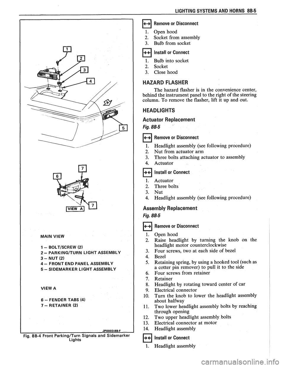
MAIN VIEW
I
1 - BOLTISCREW (2)
2 - PARKINGITURN LIGHT ASSEMBLY
3 - NUT (2)
4 - FRONT END PANEL ASSEMBLY
5 - SIDEMARKER LIGHT ASSEMBLY
VIEW A
6 - FENDER TABS (4)
7 - RETAINER (2)
Fig. 8B-4 Front Parkingflurn Signals and Sidemarker
Lights
LIGHTING SYSTEMS AND HORNS 88-5
Remove or Disconnect
1. Open hood
2. Socket from assembly
3. Bulb from socket
Install or Connect
1. Bulb into socket
2. Socket
3. Close hood
HAZARD FLASHER
The hazard flasher is in the convenience center,
behind the instrument panel to the right of the steering
column. To remove the flasher, lift it up and out.
HEADLIGHTS
Actuator Replacement
Fig. 88-5
Remove or Disconnect
1. Headlight assembly (see following procedure)
2. Nut from actuator arm
3. Three bolts attaching actuator to assembly
4. Actuator
Install or Connect
1. Actuator
2. Three bolts
3. Nut
4. Headlight assembly (see following procedure)
Assembly Replacement
Fig. 88-5
Remove or Disconnect
Open hood
Raise headlight by turning the knob on the
headlight motor counterclockwise
Four screws, two at each side of bezel
Bezel
Retaining spring, by using a hooked tool (such as
a cotter pin remover) to pull it to the side
Four screws from retainer
Retainer
Headlight by rotating toward center of car
Electrical connector
Turn the knob to lower the headlight assembly
about halfway
Two lower headlight assembly bolts by reaching
through opening
Two upper headlight assembly bolts
Electrical connector at motor
Headlight assembly
Install or Connect
1. Headlight assembly
Page 1605 of 1825
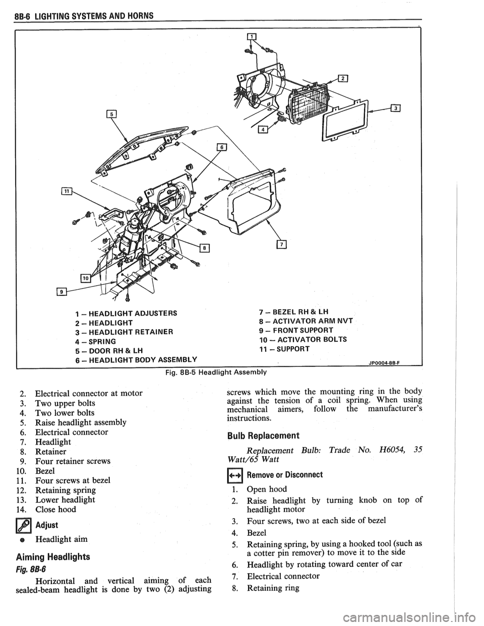
1 - HEADLIGHT ADJUSTERS 7 - BEZEL RH & LH
2 - HEADLIGHT 8 - ACTIVATOR ARM NVT
3 - HEADLIGHT RETAINER 9 - FRONT SUPPORT
4 - SPRING 10 - ACTIVATOR BOLTS
5 - DOOR RH 81 LH 11 - SUPPORT
6 - HEADLIGHT BODY ASSEMBLY JP0004-8B-F
Electrical connector at motor
Two upper bolts
Two lower bolts
Raise headlight assembly
Electrical connector
Headlight Retainer
Four retainer screws
Bezel
Four screws at bezel
Retaining spring Lower headlight
Close hood
Adjust
e Headlight aim
Aiming Headlights
Fig. 8B-6
Horizontal and vertical aiming of each
sealed-beam headlight is done by two
(2) adjusting screws
which move the mounting ring in the body
against the tension of a coil spring. When using
mechanical aimers, follow the manufacturer's
instructions.
Bulb Replacement
Replacement Bulb: Trade No. H6054, 35
Wa t
t/65 Watt
Remove or Disconnect
1. Open hood
2. Raise headlight by turning knob on top of
headlight motor
3. Four screws, two at each side of bezel
4. Bezel
5. Retaining spring, by using a hooked tool (such as
a cotter pin remover) to move it to the side
6. Headlight by rotating toward center of car
7. Electrical connector
8. Retaining ring
Page 1607 of 1825
88.8 LIGHTING SYSTEMS AND HORNS
2. Two screws
3. Light assembly
4. Socket from assembly
5. Bulb from socket
Install or Connect
1. Bulb into socket
2. Socket into assembly
3. Assembly
4. Two screws
5. License plate
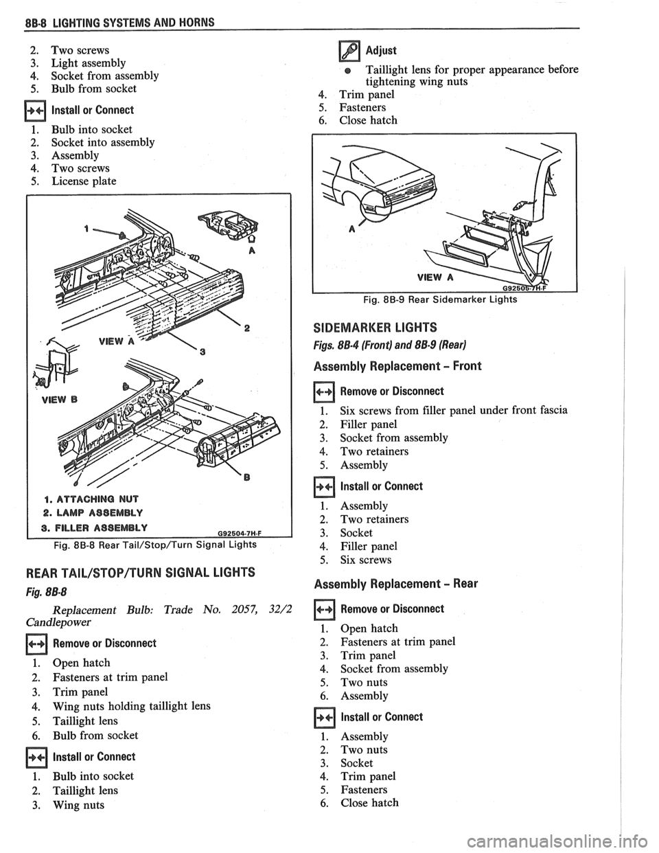
1. ATTACHING NUT
2. LAMP A98EMBLV
Fig. 88-8 Rear Tail/Stop/Turn Signal Lights
REAR TAIL/STOP/TURN SIGNAL LIGHTS
Fig. 8B-8
Replacement Bulb: Trade No. 2057, 32/2
Candlepo wer
Remove or Disconnect
1. Open hatch
2. Fasteners at trim panel
3. Trim panel
4. Wing nuts holding taillight lens
5. Taillight lens
6. Bulb from socket
Install or Connect
1. Bulb into socket
2. Taillight lens
3. Wing nuts
Adjust
Taillight lens for proper appearance before
tightening wing nuts
4. Trim panel
5. Fasteners
6. Close hatch
Fig. 88-9 Rear Sidemarker Lights
SIDEMARKER LIGHTS
Figs. 88-4 (Front) and 8B-9 (Rear)
Assembly Replacement - Front
Remove or Disconnect
1. Six screws from filler panel under front fascia
2. Filler panel
3. Socket from assembly
4. Two retainers
5. Assembly
Install or Connect
1. Assembly
2. Two retainers
3. Socket
4. Filler panel
5. Six screws
Assembly Replacement - Rear
Remove or Disconnect
1. Open hatch
2. Fasteners at trim panel
3. Trim panel
4. Socket from assembly
5. Two nuts
6. Assembly
Install or Connect
1. Assembly
2. Two nuts
3. Socket
4. Trim panel
5. Fasteners
6. Close hatch
Page 1609 of 1825
Adjust 2 . Filler panel 3 . Electrical connector
1 . Increase Current - Turn adjusting screw 4 . ~~l~/~~~~~
clockwise 5 . Horn
2 . Decrease Current . Turn adjusting screw
counterclockwise
Install or Connect
3 . Current adjustments should be made 1/4 turn
(90") at a time
Horn Assembly
Remove or Disconnect
1 . Six screws from filler panel behind front fascia on
driver's side 1
. Horn
2 . Bolt/screw
3 . Electrical connector
4
. Filler panel
5 . Six screws
Horn Relay
The horn relay is in the convenience center.
behind the instrument panel to the right of the steering
column
. To remove the relay. pull it straight out .
REPLACEMENT LIGHT BULBS
For exterior light replacement procedures. see the rest of this
section
. For interior light replacement procedures. see Section $A
and Section 8C .
EXTERIOR LIGHTS Trade No . ...................................................................................................................... Back-up Lights 1 156
Center
High-Mounted Stoplight ............................................................................................. 577
Front Barking/Turn Signal Eights ..................................................................................... 2057
Fog Lights
............................................................................................................................... H-3
Headlights ....................................................................................................................... H6054 ................................................................................................................ License Plate Lights 194
.................................................................................... Rear Tail/Stop/Turn Signal Lights 2057
Sidemarker Lights (Front and Rear) ...................................................................................... 194 ..................................................................................................................... Underhood Light 211
BNTERBOR LIGHTS Trade No .
......................................................................................... Air Conditioner/Heater Controls 194 .................................................................................................................. Ashtray & Lighter 194 .............................................................................................................. Cargo Compartment 561
................................................................................................ Cluster & Speedometer (Tach) 194 ..................................................................................................................... Console Ashtray 194 ............................................................................................................. Console Compartment 194
Courtesy Lights
..................................................................................................................... 194 ......................................................................................................................... Dome Light 561
Gear Selector Indicator
............................................................................................................ 74 .......................................................................................... Headlight High-Beam Indicator 194
Indicator Lights
..................................................................................................... Brake System Warning 194
With Gages
........................................................................................................................ 74
............................................................... Charging System Warning (except Rally Gages) 194 .................................................................................................................... Choke Warning
194
With Gages
........................................................................................................................ 74
...................................................................... Oil Pressure Warning (except Rally Gages) 194 ............................................................................................................ Seat Belt
Reminder 194
With Gages
.................................... ... ................................................................................. 74 ............................................................................................. Service Engine Soon Warning 194
With Gages
..................................................................................................................... 74 ............................................................ Temperature Gage Warning (except Rally Gages) 194
........................................................................................................................ Reading
Light 906 ............................................................................................................ Turn Signal Indicators 194
Page 1612 of 1825
INSTRUMENT PANEL, GAGES & CONSOLE 8C-'I
SECTION 8C
NSTRUMENT PANEL, GAGES & CONSOLE
CONTENTS
General Description ................................... 8C-1
Instrument Panel and Gages ........................ 8C-1
Printed Circuit .......................................... 8C-1
Instruments ................................................... 8C- 1
Speed Sensors
............................ .. ............. 8C- 1
Pinion Gear
............................................. 8C-2
Photo Speed Sensor ................................ 8C-2
PM Generator ................... .. ...... ............... 8C-2
Speedometer ................................................ 8C-2
Mechanical ....................... .. .................... 8C-2
Quartz ........................ .. .......................... 8C-2
Digital .................... .. ...... ................. 8C-2
Fuel Gage .................................................... 8C-2
Temperature Warning Light ...................... 8C-3
Generator Warning Light ............................ 8C-3
Engine Oil Pressure Light ............................ 8C-3
"Service Engine Soon" Light ....................... 8C-3
Upshift Indicator Light .............................. 8C-3
Diagnosis .................... .. ........................... 8C-3
General Information .................................. 8C-3
Instrument Panel & Gages ...................... ..... 8C-3
On-Car Service ......................... .. ........... 8C-4
Instrument Panel Pad ................................... 8C-4
Instrument Panel Cluster ........................... 8C-4
Instrument Panel Carrier ............................. 8C-4
Headlight Switch .......................................... 8C-4
Console Mounted Switches and
Accessories
............................................... 8C-4
Console ......................................................... 8C-4
Speedometer .................................................. 8C-5
Illustra3ions ................................................. 8C-5
IP Pad ........................................................... 8C-5
IP Carrier ................................................... 8C-6
Instrument Cluster ....................................... 8C-6
Lower IP Covers ......................................... 8C-7
IP Trimplates ............................................... 8C-7
IP Hush Panels; with A/C .......................... 8C-8
..................... IP Lower Trim Pad (Console) 8C-8
Map Holder or Map Pocket ........................ 8C-8
IP Hush Panels; without A/C ..................... 8C-9
Radio Mounting ........................................... 8C-9
Subwoofer & Hatch Release
Switches/Covers ........................................ 8C- 10
Foglamp Switch/Cover ................................ 8C- 10
Oil Pressure and Temperature
Switches
..................................................... 8C-11
Heater/Ventilation/Defroster
Ductwork .................................................. 8C- 12
A/C and Defroster Ductwork ..................... 8C-13
Ram Vent System Ductwork ....................... 8C-14
Console Mounted Switches
&
Accessories ................................................. 8C- 14
Dash Insulators
............................................ 8C- 15
Heater Floor Outlet
..................................... 8C-15
................ Headlamp/Parking Lamp Switch 8C- 15
............. Dash Mounted Accessory Switches 8C- 15
GENERAL DESCRIPTION
INSTRUMENT PANEL AND GAGES
INSTRUMENTS
Instruments consist of fuel gage, temperature
The instrument panel on most cars is a sing,e unit indicator light, generator light, oil pressure indicator
design and all parts attach to the main instrument light, and speedometer. See Section 9F for optional
panel with clips and screws. To service the instrument Gages and tachometer. Service on instruments
panel and components see on-car service information, can be obtained through authorized repair stations.
However, knowledge of instrument circuit checks will
PRINTED CIRCUIT
All models are equipped with printed circuits
which supply current to most instrument panel lights
and instruments. These circuits are made of copper foil
which is die cut and bonded to a polyester base film
(usually mylar). The printed circuit electrical power is
supplied by a connector containing several wires, as
shown in the instrument panel wiring harness
installation instructions. The connector also helps
retain the printed circuit to the speedo cluster. The rest
of the circuit is retained by additional connectors (if
used) and snap-in
bulbs/sockets. For individual
printed circuit diagrams, see Section
8A-80/8 1/82/83,
'Instrument Panel'. help
in determining if operating difficulties lie in the
instrument itself or its related circuit.
Instruments have been designed for easy removal
by elimination of separate wiring. With the wiring
provisions integrated with the instrument panel wiring,
the instruments can be removed after removing the
trim and lens.
SPEED SENSORS
There are three speed sensors currently in use:
1. PINION GEAR; used in mechanical systems
2. PHOTO SPEED SENSORS; used in mechanical
systems
3. PM GENERATOR; used in electronic systems
Page 1615 of 1825
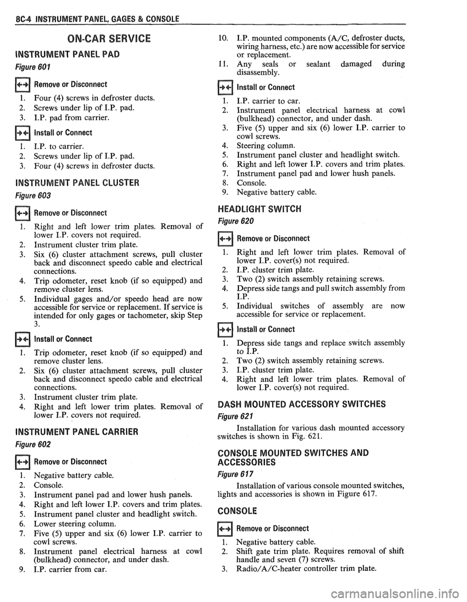
8C.4 INSTRUMENT PANEL, GAGES & CONSOLE
ON-CAR SERVlCE
lNSTRUMEMT PANEL PAD
Figure 601
Remove or Disconnect
1. Four (4) screws in defroster ducts.
2. Screws
under lip of
I.P, pad.
3. I.P. pad from carrier.
lnstall or Connect
1. I.P. to carrier.
2. Screws
under lip of I.P. pad.
3. Four (4) screws in defroster ducts.
INSTRUMENT PANEL CLUSTER
Figure 683
Remove or Disconnect
1. Right and left lower trim plates. Removal of
lower I.P. covers not required.
2. Instrument cluster trim plate.
3. Six (6) cluster attachment screws, pull cluster
back and disconnect speedo cable and electrical
connections.
4. Trip odometer, reset knob (if so equipped) and
remove cluster lens.
5. Individual gages and/or speedo head are now
accessible for service or replacement. If service is
intended for only gages or tachometer, skip Step
3.
Install or Connect
1. Trip odometer, reset knob (if so equipped) and
remove cluster lens.
2. Six
(6) cluster attachment screws, pull cluster
back and disconnect speedo cable and electrical
connections.
3. Instrument cluster trim plate.
4. Right and left lower trim plates. Removal of
lower I.P. covers not required.
INSTRUMENT PANEL CARRIER
Figure 602
Remove or Disconnect
Negative battery cable.
Console. Instrument panel pad and lower hush panels.
Right and left lower I.P. covers and trim plates.
Instrument panel cluster and headlight switch.
Lower steering column.
Five (5) upper and six (6) lower I.P. carrier to
cowl screws.
Instrument panel electrical harness at cowl
(bulkhead) connector, and under dash.
I.P. carrier from car.
10. I.P. mounted components (A/C, defroster ducts,
wiring harness, etc.) are now accessible for service
or replacement.
11. Any seals or sealant damaged during
disassembly.
Install or Connect
I.P. carrier to car.
Instrument panel electrical harness at cowl
(bulkhead) connector, and under dash.
Five (5) upper and six (6) lower I.P. carrier to
cowl screws.
Steering column.
Instrument panel cluster and headlight switch.
Right and left lower I.P. covers and trim plates.
Instrument panel pad and lower hush panels.
Console.
Negative battery cable.
HEADLIGHT SWITCH
Figure 620
Remove or Disconnect
1. Right and left lower trim plates. Removal of
lower I.P.
cover(s) not required.
2. I.P. cluster trim plate.
3. Two (2) switch assembly retaining screws.
4. Depress side tangs and pull switch assembly from
I.P.
5. Individual switches of assembly are now
accessible for service or replacement.
Install or Connect
1. Depress side tangs and replace switch assembly
to I.P.
2. Two
(2) switch assembly retaining screws.
3. I.P. cluster trim plate.
4. Right and
left lower trim plates. Removal of
lower I.P.
cover(s) not required.
DASH MOUNTED ACCESSORY SWITCHES
Figure 62 1
Installation for various dash mounted accessory
switches is shown in Fig.
62 1.
CONSOLE MOUNTED SWITCHES AND
ACCESSORIES
Figure 6 17
Installation of various console mounted switches,
lights and accessories is shown in Figure 617.
CONSOLE
Remove or Disconnect
1. Negative battery cable.
2. Shift gate trim plate. Requires removal
of shift
handle and seven (7) screws.
3. Radio/A/C-heater controller trim plate.
Page 1650 of 1825
RADIO SYSTEMS AND ANTENNAS 9A-1
SECTION 9A
0 SYSTEMS AND ANTENNAS
CONTENTS
............................................. General Description .................................... 9A-1 Radio Operation 9A-4
Radio
............................................................ 9A-1 ETR AM/FM Stereo (UM-7) ....................... 9A-4
Antennas
........................................................ 9A- 1 ETR Stereo Cassette (UM-6) ......................... 9A-5
Fixed Antenna
.......................................... 9A- 1 ETR Stereo/Cassette/Eaualizer
Diagnosis ........................................................
Radio ....................... .. ................................
Static and Noise .................................... .....
........................................ Popping Noise
Preliminary Diagnostics
.............................
Antenna ................................. .. ................
Tape Player .................. .... .......................
Service Procedures ....................................
Radio and Speakers ........................... .............
Radio Noise Suppression Equipment ............
Stereo Cassette Tape Player ..........................
Tape & Tape Player Care ........................
(UX-1) ..................................................... 9A-6
Advanced ETR
Stereo/Cassette/Equalizer Touch
Control
.................................... ... .............. 9A-7
On-Car Service .............................................. 9A-9
Radio Receiver
............................................ 9A-9
Radio Steering Wheel Controls
..................... 9A-9
Audio Amplifier
........................................... 9A-9
Radio Suppression
..................................... 9A-9
Front Speaker
................................................. 9A-9
............... Rear Speaker; Sub Woofer Speaker
9A-9
Antenna
..................... .. ............................. 9A- 10
GENERAL DESCRIPUION
RADIO ANTENNAS
For radios and radio use see the "Radio Fixed Antenna
Operation" section. ETR means 'Electronically Tuned The
fixed antenna on the right front fender
Receiver'. cannot be adjusted up or down. It may provide
improved reception in rural areas.
- The fixed antenna is designed to withstand most
car washes without damage. If the antenna becomes
slightly bent, you can straighten it by hand. The
antenna can be replaced if severely bent (by vandalism,
etc.). Antennas must be kept clean for good
performance.
RADIO
Because radio problems are normally repaired at
authorized warranty repair stations, the tendency is to
remove the set when a problem is reported, without any
preliminary diagnosis. This results in a large number
of radios being "No Trouble Found" units when
received by the warranty repair stations. Often the
trouble can be corrected without radio removal. wire.
If equipped with
A/C, the blower motor has a
built-in capacitor. Extra electrical equipment added to
the static if not properly grounded or wiring was
improperly routed.
Weak
FM station reception will be affected by
nearby buildings, car speed and direction. These
"flutter" and "fading" conditions are characteristic of
weak FM signals.
ETR radios require clock and button reset if the
battery is disconnected.
Popping Noise
Static and Noise Operating devices such as turn signals, pushing in
cigarette lighter, operating stop lights, etc., may cause
Ground strap connections must be clean and
a popping noise on distant (weak) AM signals.
tight, spark plug cables must be TVRS type and in
good condition and resistance-type spark plugs used.
Preliminary Diagnostics
Capacitors are used in the generator, heating/air
conditioning system, and fuse panel to reduce noise
The inconvenience of driving without a radio
entering the radio through the feed wires. If the car has
while the set is being serviced can often be avoided if
a heater only, the capacitor is in the blower motor feed
the following quick checks are used to eliminate