differential PONTIAC FIERO 1988 Service Repair Manual
[x] Cancel search | Manufacturer: PONTIAC, Model Year: 1988, Model line: FIERO, Model: PONTIAC FIERO 1988Pages: 1825, PDF Size: 99.44 MB
Page 16 of 1825
- -
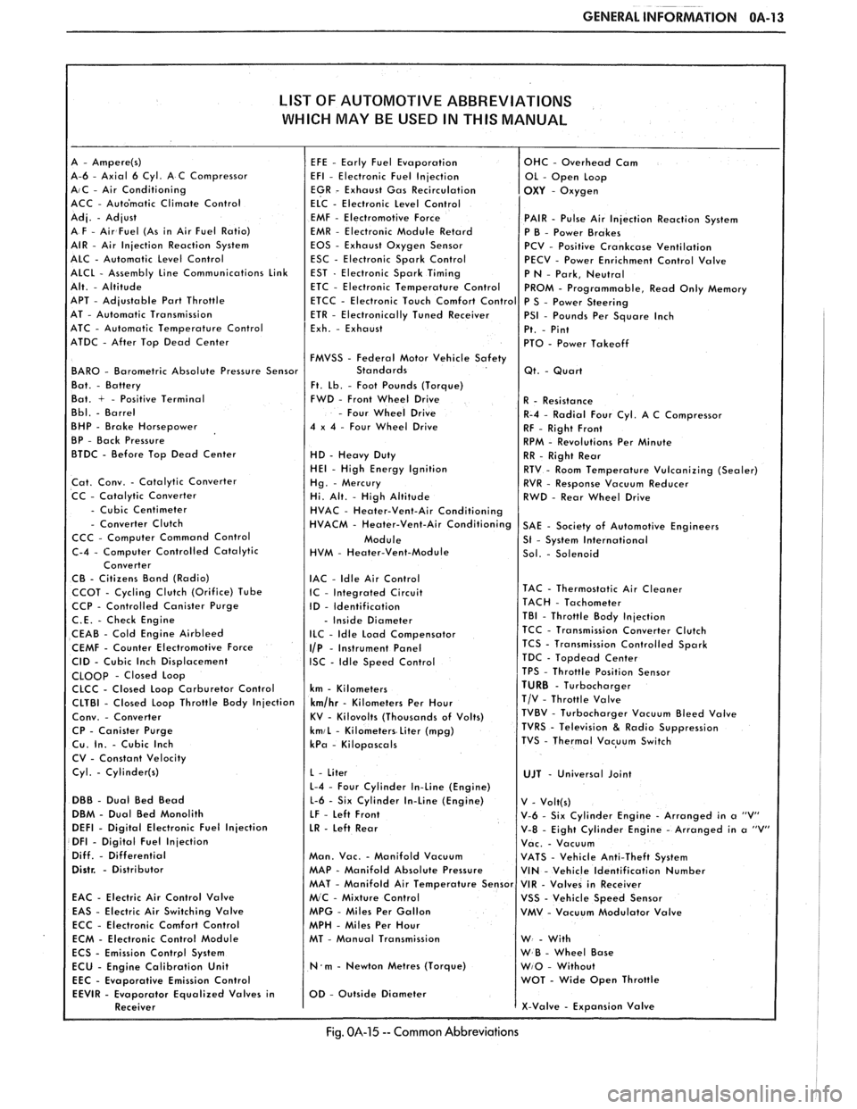
GENERAL INFORMATION OA-13
LIST OF AUTOMOTIVE ABBREVIATIONS
WHICH MAY
BE USED IN THIS MANUAL
A-6 - Axial 6 Cyl. A C Compressor AIC - Air Conditioning
ACC - Auto'matic Climate Control
EMF
- Electromotive Force PAIR - Pulse Air Injection Reaction System
EMR - Electronic Module Retard
P B - Power Brakes
EOS - Exhaust Oxygen Sensor
PCV - Positive Crankcase Ventilation
ESC - Electronic Spark Control
PECV - Power Enrichment Control Valve
APT
- Adjustable Part Throttle
AT - Automatic Transmission
ATC - Automatic Temperature Control
ATDC
- After Top Dead Center
FMVSS
- Federal Motor Vehicle Safety BAR0 - Barometric Absolute Pressure Sensor
Ft. Lb. - Foot Pounds (Torque)
Bat. + - Positive Terminal FWD - Front Wheel Drive
- Four Wheel Drive
BHP - Brake Horsepower 4 x 4 - Four Wheel Drive
BP - Back Pressure
BTDC - Before Top Dead Center
HD - Heavy Duty HE1 - High Energy Ignition
Cat. Conv. - Catalytic Converter
CC - Catalytic Converter
- Cubic Centimeter - Converter Clutch
CCC - Computer Command Control
HVM
- Heater-Vent-Module
IAC
- ldle Air Control CCOT - Cycling Clutch (Orifice) Tube IC - Integrated Circuit CCP - Controlled Canister Purge
ID - Identification
C.E. - Check Engine - Inside Diameter
CEAB - Cold Engine Airbleed ILC - Idle Load Compensator
CEMF - Counter Electromotive Force I/P - Instrument Panel
CID - Cubic Inch Displacement ISC - Idle Speed Control CLOOp - Closed Loop
CLCC - Closed Loop Carburetor Control km - Kilometers
CP
- Canister Purge kmiL - Kilometers Liter (mpg) Cu. In. - Cubic Inch kPa - Kilopascals
CV - Constant Velocity
Cyl.
- Cylinder(s)
L-4 - Four Cylinder In-Line (Engine)
DBB - Dual Bed Bead L-6 - Six Cylinder In-Line (Engine)
DBM - Dual Bed Monolith
LF - Left Front DEFl - Digital Electronic Fuel Injection LR - Left Rear DFI - Digital Fuel Injection
Diff. - Differential Man. Vac. - Manifold Vacuum Distr. - Distributor MAP - Manifold Absolute Pressure
EAC
- Electric Air Control Valve
EAS - Electric Air Switching Valve MPG - Miles Per Gallon
ECC - Electronic Comfort Control
MPH - Miles Per Hour
ECM - Electronic Control Module MT - Manual Transmission
N.m - Newton Metres (Torque)
Emission Control
Fig. 014-15 -- Common Abbreviations
Page 230 of 1825
REAR SUSPENSION 3D-9
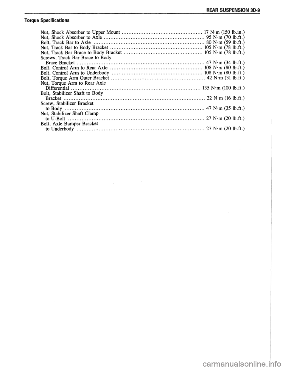
"Torque Specifications
................................................ Nut. Shock Absorber to Upper Mount 17 N.m (150 1b.in.)
............................................................ Nut. Shock Absorber to Axle 95 N-m (70 1b.ft.) .................................................................. Bolt. Track Bar to Axle 80 N.m (59 1b.ft.)
....................................................... Nut. Track Bar to Body Bracket 105 N-m (78 1b.ft.)
............................................... Nut. Track Bar Brace to Body Bracket 105 N-m (78 1b.ft.)
Screws. Track Bar Brace to Body ............................................................................ Brace Bracket 47 N.m (34 1b.ft.)
....................................................... Bolt. Control Arm to Rear Axle 108 N-m (80 1b.ft.)
...................................................... Bolt. Control Arm to Underbody 108 N.m (80 1b.ft.)
........................................................ Bolt. Torque Arm Outer Bracket 42 N.m (31 1b.ft.)
Nut. Torque Arm to Rear Axle ............................................................................. Differential 135 N-m (100 1b.ft.)
Bolt. Stabilizer Shaft to Body
Bracket
.................................................................................... 22 N.m (16 1b.ft.)
Screw. Stabilizer Bracket ................................................................................... to Body 47 Nam (35 1b.ft.l
Nut. Stabilizer Shaft Clamp ................................................................................. to U-Bolt 27 N-m (20 1b.ft.)
Bolt. Axle Bumper Bracket ............................................................................ to Underbody 27 N-m (20 1b.ft.)
Page 242 of 1825
PROPELLER SHAFT 4A-1
PROPELLER SHAFT
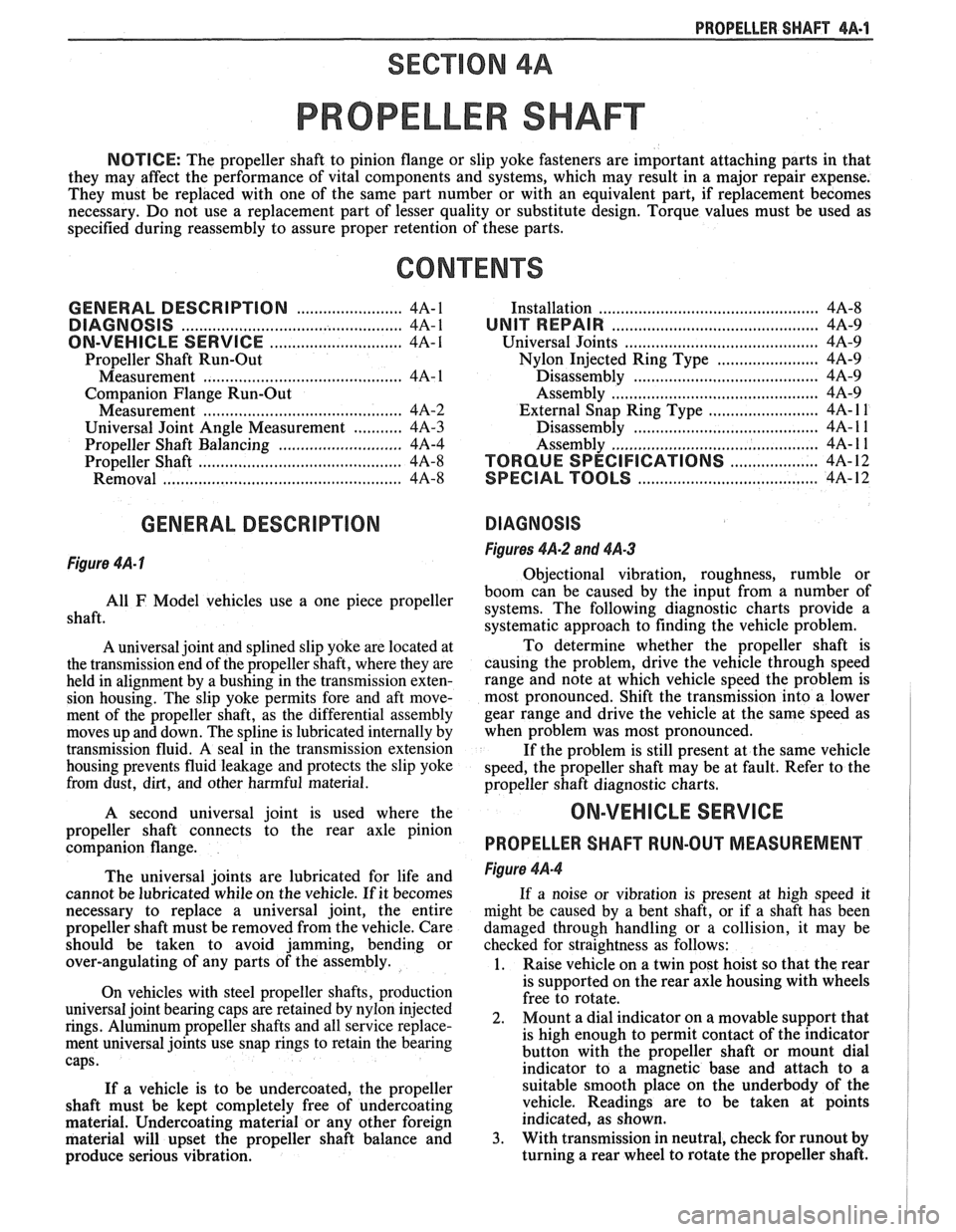
NOTICE: The propeller shaft to pinion flange or slip yoke fasteners are important attaching parts in that
they may affect the performance of vital components and systems, which may result in a major repair expense.
They must be replaced with one of the same part number or with an equivalent part, if replacement becomes
necessary. Do not use a replacement part of lesser quality or substitute design. Torque values must be used as
specified during reassembly to assure proper retention of these parts.
CONTENTS
GENERAL DESCRIPTION ........................ 4A-1
DIAGNOSIS ......................... ............ 4A-1
ON-VEHICLE SERVICE ........................... 4A-I
Propeller Shaft Run-Out
....................................... Measurement 4A- 1
Companion Flange Run-Out
Measurement
............................................. 4A-2
........... Universal Joint Angle Measurement 4A-3
............................ Propeller Shaft Balancing 4A-4
.............................................. Propeller Shaft 4A-8
Removal
.................... .. ............................. 4A-8
GENERAL DESCRIPTION
Figure 4A- I
.............................................. Installation 4A-8
UNIT REPAIR ............................................... 4A-9
Universal Joints
...................... ... ............ 4A-9
....................... Nylon Injected Ring Type 4A-9
..... ....................... Disassembly .... 4A-9
.......................................... Assembly 4A-9
......................... External Snap Ring Type 4A- l 1
............. .................... Disassembly .. 4A- 1 1
........................................... Assembly
4A- 1 1
.................... TORQUE SPECIFICATIONS 4A-12
.................................. SPECIAL TOOLS 4A-12
DIAGNOSIS
Figures 4A-2 and 4A-3
Obiectional vibration, roughness, rumble or
boom
can be caused by the input from a number of
shaft. use a One piece propeller systems. The following diagnostic charts provide a
systematic approach to finding the vehicle problem.
A universal joint and splined slip yoke are located at
the transmission end of the propeller shaft, where they are
held in alignment by a bushing in the transmission exten-
sion housing. The slip yoke permits fore and aft move-
ment of the propeller shaft, as the differential assembly
moves up and down. The spline is lubricated internally by
transmission fluid. A seal in the transmission extension
housing prevents fluid leakage and protects the slip yoke
from dust,
dirt, and other harmful material.
A second universal joint is used where the
propeller shaft connects to the rear axle pinion
companion flange.
The universal joints are lubricated for life and
cannot be lubricated while on the vehicle.
If it becomes
necessary to replace a universal joint, the entire
propeller shaft must be removed from the vehicle. Care
should be taken to avoid jamming, bending or
over-angulating of any parts of the assembly.
On vehicles with steel propeller shafts, production
universal joint bearing caps are retained by nylon injected
rings. Aluminum propeller shafts and all service replace-
ment universal joints use snap rings to retain the bearing
caps.
If a vehicle is to be undercoated, the propeller
shaft must be kept completely free of undercoating
material. Undercoating material or any other foreign
material will upset the propeller shaft balance and
produce serious vibration. To
determine whether the propeller shaft is
causing the problem, drive the vehicle through speed
range and note at which vehicle speed the problem is
most pronounced. Shift the transmission into a lower
gear range and drive the vehicle at the same speed as
when problem was most pronounced.
If the problem is still present at the same vehicle
speed, the propeller shaft may be at fault. Refer to the
propeller shaft diagnostic charts.
ON-VEHICLE SERVICE
PROPELLER SHAFT RUN-OUT MEASUREMENT
Figure 4A-4
If a noise or vibration is present at high speed it
might be caused by a bent shaft, or if a shaft has been
damaged through handling or a collision, it may be
checked for straightness as follows:
1. Raise vehicle on a twin post hoist so that the rear
is supported on the rear axle housing with wheels
free to rotate.
2. Mount
a dial indicator on a movable support that
is high enough to permit contact of the indicator
button with the propeller shaft or mount dial
indicator to a magnetic base and attach to a
suitable smooth place on the underbody of the
vehicle. Readings are to be taken at points
indicated, as shown.
3. With transmission in neutral, check for runout by
turning a rear wheel to rotate the propeller shaft.
Page 243 of 1825
4A-2 PROPELLER SHAFT
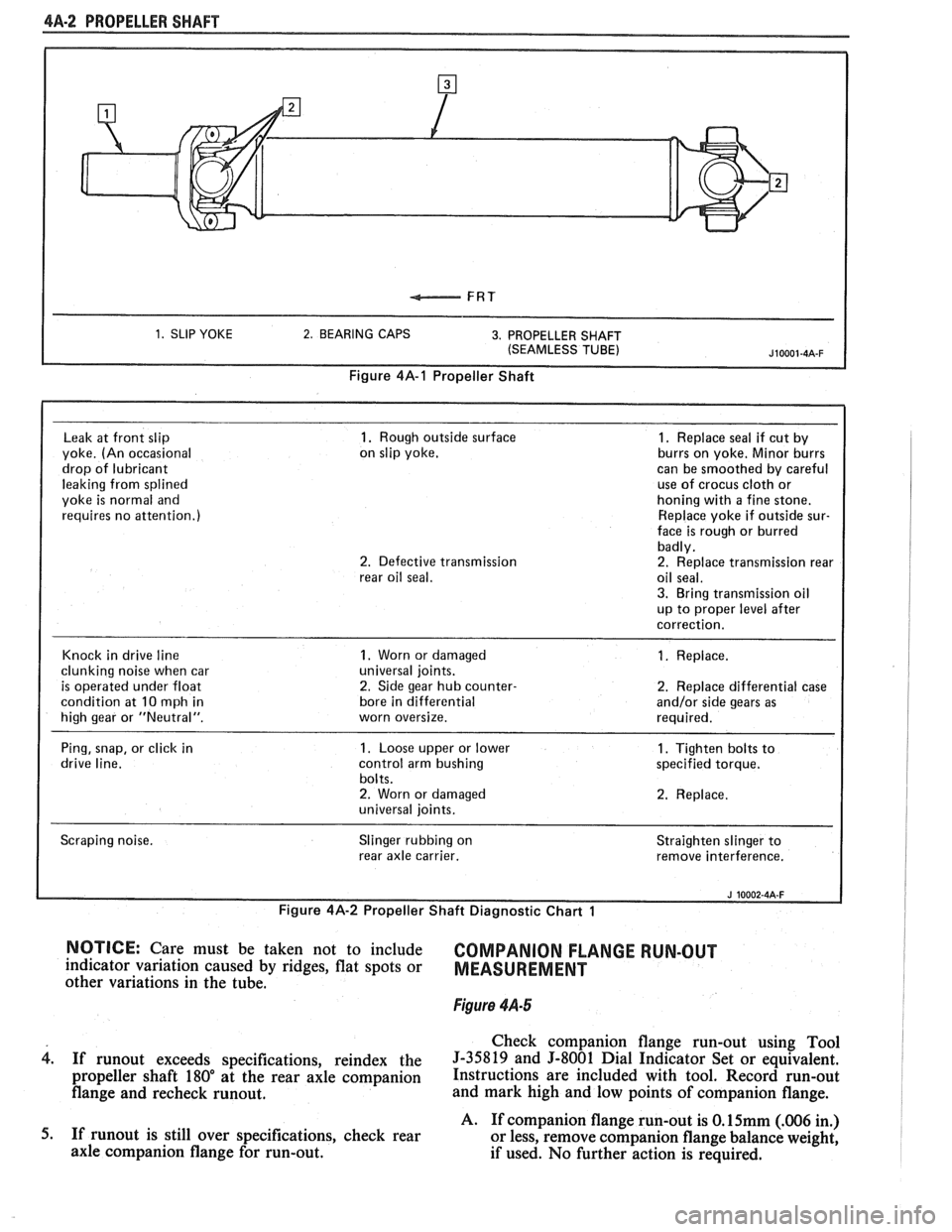
1. SLIP YOKE 2. BEARING CAPS 3. PROPELLER SHAFT
(SEAMLESS TUBE)
Figure 4A-1 Propeller Shaft
Leak
at front slip 1. Rough outside surface 1. Replace seal if cut by
yoke. (An occasional on
slip yoke. burrs on yoke.
Minor burrs
drop of lubricant can
be smoothed by careful
leaking from splined use
of crocus
cloth or
yoke
is normal and honing
with a fine stone.
requires no attention.) Replace
yoke if outside sur-
face is rough or burred
badly.
2. Defective transmission 2. Replace transmission rear
rear oil seal. oil seal.
3. Bring transmission oil
up to proper level after
correction.
Knock in drive line
1. Worn or damaged 1. Replace.
clunking noise when car universal
joints.
is operated under float 2. Side gear hub counter- 2. Replace differential case
condition at
10 mph in bore
in differential and/or side gears as
high gear or "Neutral". worn oversize. required.
Ping, snap, or click in
1. Loose upper or lower 1. Tighten bolts to
drive line. control arm bushing specified torque.
bolts.
2. Worn or damaged 2. Replace.
universal joints.
Scraping noise. Slinger
rubbing on
rear axle carrier. Straighten
slinger to
remove interference.
I
Figure 4A-2 Propeller Shaft Diagnostic Chart 1 I i
NOTICE: Care must be taken not to include COMPANION FLANGE RUN-OUT indicator variation caused by ridges, flat spots or MEASUREMENT other variations in the tube.
Figure 4.4-5
Check companion flange run-out using Tool
4. If runout exceeds specifications, reindex the 5-35819 and 5-8001 Dial Indicator Set or equivalent.
propeller shaft 180" at the rear axle companion Instructions are included with tool. Record run-out
flange and recheck runout. and mark high and low points of companion flange.
A. If companion flange run-out is
O.15mm (.006 in.)
5. If
runout is still over specifications, check rear
or less, remove companion flange balance weight,
axle companion flange for run-out.
if used. No further action is required.
Page 244 of 1825
PROPELLER SHAFT $A-3
B. If companion flange run-out is over 0.15mm (.006
in.) but less than 0.28mm (.011 in.) and balance
weight is at or near low point of companion flange
run-out, no further action is required.
If balance weight is not at or near low point of
companion flange run-out, remove weight.
6. If companion flange run-out is over 0.28mm (.011
in.), but no greater than 0.38mm (.015 in.) and
balance weight is at or near low point of
companion flange run-out, no further action is
required.
If balance weight is not at or near low point of
companion flange
runout, remove weight and
reindex companion flange until run-out is 0.25
mm
(.010 in.) or less.
If impossible to achieve
0.25mm (.010 in.) or less
run-out, install a new companion flange and
recheck for
0.25mm (.010 in.) or less run-out.
Service replacement companion flanges are not
equipped with balance weights and no weights
should be added.
UNIVERSAL JOINT ANGLE MEASUREMENT
When torque is transmitted through any ordinary
universal joint, the driven yoke fluctuates slightly in
speed. In other words, although the driving yoke
rotates at a constant speed, the driven yoke speeds up
and slows down twice per revolution. This flucutation
of the driven yoke is in direct proportion to the angle
through which the universal joint is operating; the
greater the angle, the greater the fluctuation.
Whenever two universal joints are used, this
fluctuation effect can be eliminated by staggering the
joints so that the two driving yokes are 90 degrees apart
provided the two joints are transmitting torque
through the same angle.
Therefore, when two universal joints are used, the
angles through which they operate must be very nearly the
same. This allows the alternate acceleration and decelera-
tion of one joint to be offset by the alternate acceleration
and deceleration of the second joint. When the two joints
do not run at approximately the same angle, operation is
rough and an objectionable vibration is produced.
The actual optimum angles desired must take into
consideration the effects of various passenger loadings
and rear axle windup during acceleration; therefore, it
is unlikely that the front and rear universal joint angles
will be found to be the same in actual practice.
In addition, universal joints are designed to
operate safely and efficiently within certain angles. If
the designed angle is exceeded, the joint may be broken
or otherwise damaged.
The front universal joint angle is actually the
angle between the engine-transmission centerline and
the propeller shaft centerline. This angle is determined
by the design of the frame assembly and may be altered
by adding or removing shims between the transmission
and the transmission mount.
Adding one shim at the transmission mount will
decrease the transmission universal joint angle by
1/2"
and increase differential universal joint angle by 1/4".
If one shim is removed the tranmission angle will
increase
1/2" and decrease differential angle I/@. The
production transmission mount bolt is an
M10-1.5 x 35
mm. When installing two or more shims, an
M10-1.5
x 50 mm bolt must be used.
All complaints of propeller shaft vibrations
should be accompanied by rear trim height
measurements at curb weight. An incorrect trim height
may cause some vibration. If vibration is severe
enough, removal or installation of spring shims may be
required. If any irregular roughness or vibration is
detectable in the drive line, the front and rear universal
joint angles should be checked. Should the vehicle
become involved in a severe rear end collision, or
should the rear axle carrier be replaced, the rear
universal joint angle should be checked and control
arms should be replaced if necessary.
Figure 4A-6
This method can be used with the vehicle over a
pit or on a drive-on platform hoist, as long as the
vehicle is at curb weight with a full tank of gasoline.
Bounce vehicle up and down to assure curb height.
Before universal joint angles can be checked, the
measurements specified (the distance between the top
of the axle tube and the bottom of the frame) must be
met. To insure an accurate measurement, weight may
have to be added to the vehicle to reach these
specifications.
Readings should be taken at the following
locations in the following manner.
Angle Measurement at Rear Universal Joint
Figures 4A-7 and 4A-8
1. Place inclinometer J 23498-A on rear propeller
shaft bearing cap. Center bubble in sight glass and
record measurement. Bearing cap must be straight
up and down and free of dirt or other foreign mate-
rial to obtain an accurate measurement.
2. Rotate propeller shaft 90 degrees and place
inclinometer on the companion flange bearing
cap. Center bubble in sight glass and record
measurement.
3. Subtract smaller figure from larger figure to
obtain existing rear universal joint angle.
Angle Measurement at Front Universal Joint
Figures 4A.9 and 4A- 10
1. Place inclinometer on front propeller shaft
bearing cap. Center bubble in sight and record
measurement.
2. Rotate propeller shaft 90 degrees and place
inclinometer on the slip yoke bearing cap. Center
bubble on sight glass and record measurement.
3. Substract smaller figure from larger figure
lo
obtain existing front universal joint angle.
Page 250 of 1825
PROPELLER SHAFT 4A-9
damage, do not place any tool betvveen pro-
peller shaft yoke and the universal joint
spider.
When making the rear propeller shaft connection,
be sure to align marks made on the pinion flange and
propeller shaft prior to removal.
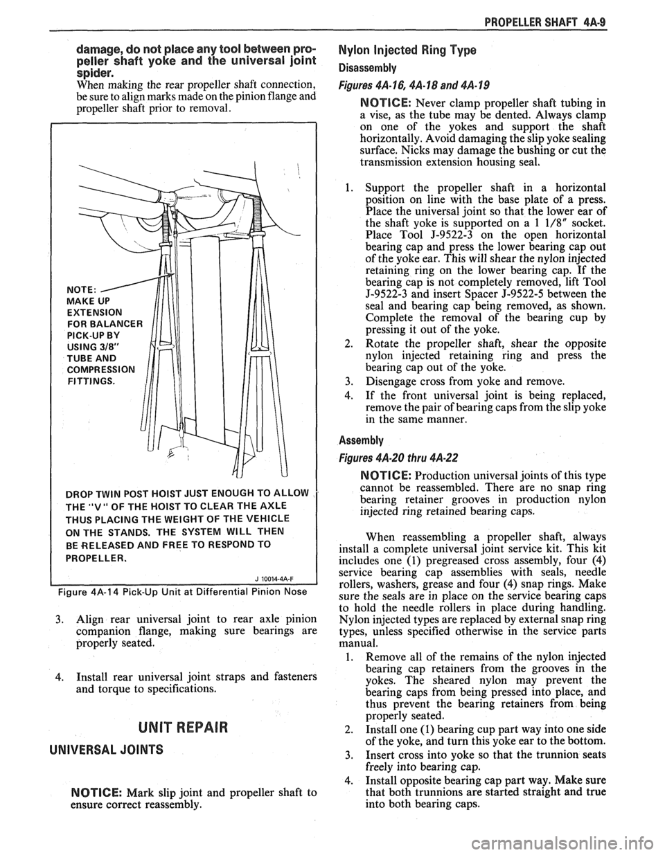
DROP TWIN POST HOIST JUST ENOUGH TO ALLOW
THE
"V" OF THE HOIST TO CLEAR THE AXLE
THUS PLACING THE WEIGHT OF THE VEHICLE
ON THE STANDS. THE SYSTEM
WILL THEN
BE RELEASED AND FREE TO RESPOND TO
PROPELLER.
Figure 4A-14 Pick-Up Unit at Differential Pinion Nose
3. Align rear universal joint to rear axle pinion
companion flange, making sure bearings are
properly seated.
4. Install rear universal joint straps and fasteners
and torque to specifications.
UNIT REPAIR
UNIVERSAL JOINTS
NOTICE: Mark slip joint and propeller shaft to
ensure correct reassembly.
Nylon Injected Ring Type
Disassembly
Figures 4A-16,4A-18 and 4A-19
NOTICE: Never clamp propeller shaft tubing in
a vise, as the tube may be dented. Always clamp
on one of the yokes and support the shaft
horizontally. Avoid damaging the slip yoke sealing
surface. Nicks may damage the bushing or cut the
transmission extension housing seal.
1. Support the propeller shaft in a horizontal
position on line with the base plate of a press.
Place the universal joint so that the lower ear of
the shaft yoke is supported on a
1 1/8" socket.
Place Tool
J-9522-3 on the open horizontal
bearing cap and press the lower bearing cap out
of the yoke ear. This will shear the nylon injected
retaining ring on the lower bearing cap. If the
bearing cap is not completely removed, lift Tool
5-9522-3 and insert Spacer J-9522-5 between the
seal and bearing cap being removed, as shown.
Complete the removal of the bearing cup by
pressing it out of the yoke.
2. Rotate
the propeller shaft, shear the opposite
nylon injected retaining ring and press the
bearing cap out of the yoke.
3. Disengage cross from yoke and remove.
4. If the front universal joint is being replaced,
remove the pair of bearing caps from the slip yoke
in the same manner.
Assembly
Figures 4A-20 thru 4A-22
NOTICE: Production universal joints of this type
cannot be reassembled. There are no snap ring
bearing retainer grooves in production nylon
injected ring retained bearing caps.
When reassembling a propeller shaft, always
install a complete universal joint service kit. This kit
includes one
(1) pregreased cross assembly, four (4)
service bearing cap assemblies with seals, needle
rollers, washers, grease and four
(4) snap rings. Make
sure the seals are in place on the service bearing caps
to hold the needle rollers in place during handling.
Nylon injected types are replaced by external snap ring
types, unless specified otherwise in the service parts
manual.
1. Remove all of the remains of the nylon injected
bearing cap retainers from the grooves in the
yokes. The sheared nylon may prevent the
bearing caps from being pressed into place, and
thus prevent the bearing retainers from being
properly seated.
2. Install one (1) bearing cup part way into one side
of the yoke, and turn this yoke ear to the bottom.
3. Insert cross into yoke so that the trunnion seats
freely into bearing cap.
4. Install opposite bearing cap part way. Make sure
that both trunnions are started straight and true
into both bearing caps.
Page 254 of 1825
REAR AXLE 481-1
SECTION 4B4
BORG WARNER REAR AXLE
NOTICE: All rear axle attaching fasteners are an
necessary. Do not use a replacement part of lesser
important part in that they could affect the
quality or substitute design. Torque values must
performance of vital parts and systems, and/or
be used as specified during reassembly to assure
could result in major repair expense. They must
proper retention of all parts. (There is to be no
be replaced with one of the same part number or
welding as it may result in extensive damage and
with an equivalent part if replacement becomes
weakening of the metal.)
CONTENTS
General Description ............................... 4B 1- I
......... Standard Rear Axle ................... ..... 4B 1 - 1
General Information ............................. .... 4B 1- 1
Limited-Slip Rear Axle .............................. 4B 1-2
Operation
............................................ 4B 1-3
Diagnosis and Testing .......................... 4B 1-2
Axle Noises
..................... .... .................. 4B 1-2
Gear Noise
................................... .... .. 4B 1-4
Bearing Noise
......................... ...... ... 4B 1-4
Rear Wheel Bearing Noise ..................... 4B 1-4
Knock At Low Speeds
....................... ..... 4B 1-4
Backlash Clunk
................................... 4B 1-4
Diagnosis
................................................ 4B 1-4
Pre-Repair Investigation and Trouble
Diagnosis
....................... .. .................... 4B 1-4
...................................... On-Vehicle Sewice 4B 1-7
Carrier Cover and Gasket .......................... 4B 1-7
.............. Axle Shaft ......................... ....., 4B 1-7
Tooth Contact Pattern Test
................... 4B 1-8
Procedure
.................... .. ...................... 4B 1-8
Effects of Increasing Load on
Teeth Contact Pattern
......................... 4B 1-8
Adjustments Affecting Tooth
................................................ Contact 4B 1-8
Effects of Pinion
Postion on Tooth Pattern
............................................... 4B
1-8
Pinion Oil Seal and Companion
Flange Replacement
................... .. ...... 4B 1-8
Rear Wheel Bolt
........................................ 4B 1 - 10
Rear Axle Assembly
................................... 4B I - 10
Unit Repair
............................................... 4Bl-1 1
Drain Rear Axle Assembly ........................ 4B I - I I
Differential Assembly ............................. 4B 1 - 1 1
Hypoid Pinion & Pinion Bearings .......... 4B 1- I I
Four Pinion Standard Differential
Assembly
....................... ... ........... 4B 1 - 1 3
Inspection
............................................ 4B 1 - I:!
Differential Assembly .......................... 4B 1 - 14
Differential Bearing Preload Spacer
................... ...................... Selection .. 4B I - 11
.................................................. Pinion 4B 1 - 15
Operation of Limited Slip Rear Axle
........................................... (Cone Type) 4B 1 - 17
Checking Limited-Slip Function
............ 4B 1 - 17
......................... Limited Slip Differential 4B 1 - 18
.............. Disassembly Inspection Chart 4B
1- 18
......................... Limited Slip Differential 4B I - 1 X
............................................. Specifications
4B 1- 19
Axle Code Identification Chart
............ 4B 1-19
............................................. Special Tools 4B 1-20
GENERAL DESCRIPTION
STANDARD REAR AXLE All parts necessary to transmit power from the
propeller shaft to the rear wheels are enclosed in a
The rear axle assembly is of the semi-floating type salisbury type axle housing (a carrier casting with tubes
in which the car weight is carried on the axle housing.
pressed and welded into the carrier to form a complete The rear axle assembly is designed for use with an open carrier and tube assembly). A removable steel cover drive line and coil springs. The rear axle has a hypoid bolted to the rear of the carrier permits service of the type ring gear and pinion with the centerline of the rear axle without removing the entire assembly from
pinion gear below the centerline of the ring gear.
the car.
GENERAL INFORMATION
NOTICE: Most rear axle service repairs can be
Two pre-loaded tapered roller bearings support the
made with the rear axle assembly in the car, by
hypoid pinion gear in the carrier. The inner race of the
raising the rear end of the car with the rear axle
rear bearing is a tight press fit on the pinion stem. The
hanging on the shock absorbers.
inner race of the front bearing combines a light press
fit to a close sliding fit on the pinion flange end of the
A universal joint connects the rear end of the pinion stem. The outer race of each bearing is pressed
propeller shaft to a companion flange having a splined against a shoulder recessed in the carrier. Tightening
end which fits over and drives the
hypoid pinion gear. the pinion nut compresses a collapsible spacer which
Page 255 of 1825
4819 REAR AXLE
bears against the inner race of the front bearing and a
shoulder on the pinion stem. This spacer is used to
enable accurate bearing pre-load adjustment and
maintain a pre-load on both front and rear pinion
bearings, Adjustment of the fore and aft position of the
pinion is obtained by placing a shim between the rear
pinion bearing cup and axle housing. The differential
case is of two-piece construction and is supported in
the carrier by two tapered roller side bearings. Pre-load
rear axle case by inserting shims between the bearings
and the carrier. The rear axle case assembly is
positioned for proper ring gear to pinion backlash by
varying the shim thickness from side to side. The ring
gear is bolted to the case. Two side gears have splined
bores for driving the axle shafts. They are positioned
to turn in counterbored cavities in the case. The four
rear axle pinions have smooth bores and are held in
position by a pinion cross shaft, mounted and locked
in the rear axle case. All six gears are in mesh with each
other and because the pinion gears turn freely on their
shaft, they act as idler gears when the rear wheels are
turning at different speeds. The pinions and side gears
are backed by steel thrust washers.
LIMITED-SLIP REAR AXLE
The operation of the Limited-Slip differential is
the same as the standard differential, except that there
is additional friction provided by the conical clutches.
Under ordinary driving and cornering conditions, the
cones slip, allowing the outside wheel to turn faster
than the inner. Under poor traction conditions, such as
ice, snow, or loose gravel under one driving wheel, the
increased friction provided by the cones increases the
driving torque available to the wheel with the better
traction. The cones are spring loaded to provide the
increased driving torque under extremely low traction
conditions.
Operation
When the vehicle turns a corner, the outer rear
wheel must turn faster than the inner wheel. The inner
wheel, turning slower than the outer wheel, slows its
differential side gear (as the axle shaft is splined to the
side gear) and the differential pinion gears will roll
around the slowed differential side gear, driving the
other differential side gear and wheel faster.
DIAGNOSIS AND TESTING
Many noises reported as coming from the rear
axle assembly actually originate from other sources
such as tires, road surfaces, front wheel bearings, axle
bearing, engine, transmission, muffler or body
drumming. A thorough and careful check should be
made to determine the source of the noise before
disassembling the rear axle. Noise which originates in
other places cannot be corrected by adjustment or
replacement of parts in the differential. It should also
be remembered that rear axle gears, like any other
mechanical device, are not absolutely quiet and should
be accepted as being commercially quiet unless some
abnormal noise is present.
To make a systematic check for axle noise under
standard conditions, observe the following:
1. Select a level smooth asphalt road to reduce tire
noise and body drumming.
2. Check rear axle lubricant to assure correct level,
then drive car far enough to thoroughly warm up
rear axle lubricant, approximately 10 miles.
3. Note speed and RPM at which noise occurs. Stop
car and put transmission in neutral. Run engine
slowly up and down through engine speeds,
corresponding to car speed at which noise was
most pronounced, to determine if it is caused by
exhaust, muffler roar or other engine conditions.
4. Tire noise changes with different road surfaces,
but rear axle noise does not. Temporarily
inflating all tires to approximately 50 pounds
pressure
for test purposes only will materially
alter noise caused by tires, but will not affect noise
caused by rear axle. Rear axle noise usually stops
when coasting at speeds under 30 miles per hour;
however, tire noise continues, but with lower
tone, as car speed is reduced. Rear axle noise
usually changes when comparing acceleration
and coast, but tire noise remains about the same.
Distinguish between tire noise and rear axle noise
by noting if noise varies with various speeds or
sudden acceleration and deceleration; exhaust
and axle noise show variations under these
conditions while tire noise remains constant and
is more pronounced at speeds of 20 to 30 miles
per hour. Further check for tire noise by driving
car over smooth pavements or dirt roads (not
gravel) with tires at normal pressure. If noise is
caused by tires, it will noticeably change or
disappear and reappear with changes in road
surface.
5. Loose or rough front wheel bearings will cause
noise which may be confused with rear axle
noises; however, front wheel bearing noise does
not change when comparing drive and coast.
Light application of brakes while holding car
speed steady will often cause wheel bearing noise
to diminish, as this takes some weight off the
bearing. Front wheel bearings may be easily
checked for noise by jacking up the wheels and
spinning them, also by shaking wheels to
determine if bearings are loose.
6. Rear suspension rubber bushings and spring
insulators dampen out rear axle noise when
correctly installed. Check to see that no metallic
contact exists between the spring and spring seat
opening in frame or between upper and lower
control arm bushings and frame or axle housing
brackets. The track bar and torque arm must be
bolted securely. Metal-to-metal contact at those
points may result in telegraphing road noise and
normal axle noise which would not be
objectionable if dampened by bushings.
AXLE NOISES
After the noise has been determined as being in
the axle by following the above appraisal procedure,
the type of axle noise should be determined to aid in
making repairs if necessary.
Page 256 of 1825
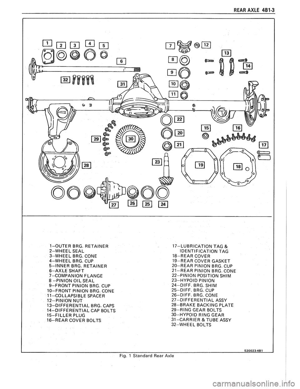
REAR AXLE 481-3
1-OUTER BRG. RETAINER
2-WHEEL SEAL
3-WHEEL BRG. CONE
4-WHEEL
BRG. CUP
5-INNER BRG. RETAINER
6-AXLE SHAFT
7-COMPANION FLANGE
8 -PINION OIL SEAL
9-FRONT PINION BRG. CUP
10-FRONT PINION BRG. CONE
1 1-COLLAPSIBLE SPACER
12-PINION NUT
13-DIFFERENTIAL
BRG. CAPS
14-DIFFERENTIAL CAP BOLTS
15-FILLER PLUG
16-REAR COVER BOLTS 17-LUBRICATION
TAG
&
IDENTI FlCATlON TAG
18-REAR COVER
19-REAR COVER GASKET
20-REAR PINION BRG. CUP
21-REAR PlNlON BRG. CONE
22-PINION POSITION
SHIM 23-HYPOID PlNlON
24-DIFF. BRG. SHIM
25-DIFF.
BRG. CUP
26-DIFF. BRG. CONE
27-DIFFERENTIAL ASSY
28-BRAKE BACKING PLATE
29-RING GEAR BOLTS
30-HYPOID
RING GEAR
31-CARRIER &TUBE ASSY
32-WHEEL BOLTS
Fig.
1 Standard Rear Axle
Page 257 of 1825
481-4 REAR AXLE
Gear Noise
Gear noise (whine) is audible from 20 to 55 mph
under four driving conditions:
1. Light Acceleration - Accelerate slowly.
2. Road Load
- Car
driving load or constant speed.
3. Float - Using enough throttle to keep the car from
driving the engine
- car slows down gradually but
engine still pulls slightly.
4. Coast - Throttle closed and car in gear.
Bearing Noise
Bad bearings generally produce more of a rough
growl or grating sound, rather than the whine typical
of gear noise. Bearing noise frequently "wow-wows" at
bearing rpm, indicating a defective pinion or rear axle
case side bearing. This noise could easily be confused
with rear wheel bearing noise. Inspect and replace as
required.
Rear Wheel Bearing Noise
A rough rear wheel bearing produces a noise
which continues with car coasting at low speed and
transmission in neutral. Noise may diminish some by
gentle braking. With rear wheels jacked up, spin rear
wheels by hand while listening at hubs for evidence of
rough (noisy) wheel bearing.
Knock At Low Speeds
Low speed knock can be caused by worn
universal joints or a side gear hub counterbore in a case
that has worn oversize. Inspect and replace universal
joint or case and side gear as required.
Backlash Clunk
Excessive clunk with acceleration and deceleration
is caused by worn differential pinion gear shaft, excessive
clearance between axle shaft and side gear splines, exces-
sive clearance between side gear hub and counterbore in
case, worn pinion and side gear teeth, worn thrust washers
and excessive drive pinion and ring gear backlash. Re-
move worn parts and replace as required, selecting close
fitting parts when possible. Adjust pinion and ring gear
backlash.
DIAGNOSIS
1. Noise
is the same in "Light Acceleration" or
"Coast".
a. Road noise.
b. Tire noise.
c. Front wheel bearing noise.
d. Rear axle bearing noise.
2. Noise changes on a different type of road.
a. Road noise.
b. Tire noise.
3. Noise tone lowers as car speed is lowered.
a. Tire noise.
b. Front
wheel bearings and rear axle bearings.
c. Gear noise.
4. Similar noise is produced with car standing and
driving. a.
Engine noise.
b. Transmission noise.
c. Exhaust noise.
5. Vibration.
a. Rough rear axle bearing.
b. Unbalanced or damaged propeller shaft.
c. Tire unbalance.
d. Worn universal joint in propeller shaft.
e. Mis-indexed propeller shaft at pinion
flange.
f. Pinion flange runout too great.
6. A knock or click approximately every two
revolutions of the rear wheel.
a. A rear axle bearing.
b. Worn case.
7. Noise most pronounced on turns.
a. Rear axle side gear and pinion noise,
differential gear noise.
b. Axle bearings.
8. A continuous low pitch whirring or scraping
noise starting at relatively low speed.
a. All bearing noise.
9. Drive noise, coast noise or float noise.
a. Ring
and pinion gear noise.
b. Front
pinion bearing noise, coast or drive.
c. Axle bearing noise.
10. Clunk
on
acceleration or deceleration.
a. Worn
rear axle pinion shaft splines.
b. Side
gear hub counterbore in case worn
oversize.
c. Worn U-joints.
d. Excessive transmission backlash.
e. Worn axle shaft splines.
11. Chatter on turns.
a. Wrong
lube in rear axle.
b. Clutch
cone worn or spalled.
12. Clunk
or knock on rough road operation.
a. Worn suspension bushings.
PRE-REPAIR INVESTIGATION AND TROUBLE
DIAGNOSIS
A carefull diagnosis of the rear axle prior to
disassembly will often reveal valuable information as to
the extent and type of repairs or adjustments necessary.
Since frequent causes of axle noises are improper
backlash, pinion bearing pre-load, or side bearing
pre-load, or a combination, a few simple adjustments
may be all that are necessary to correct a problem.
Before disassembling the rear axle, the following
checks should be made with the results recorded and
analyzed: 1) Backlash;
2) Total Assembly Preload; 3)
Tooth Contact Pattern Test; 4) Fluid Level; and 5)
Fluid Contamination.
If axle shaft end play is excessive then check
bearings, retainer, and bolts securing backing plate.
The axle bearings could be worn and need replacement.
The four bolts or nuts securing the brake backing plate
may be loose, stripped, or missing. If the inner bearing
retainer worked loose it must be replaced.
Use care at all times to keep dirt and other foreign
matter, such as grinder dust, soot or sand, away from
differential to prevent possibility of subsequent failure.