automatic transmission PONTIAC FIERO 1988 Service User Guide
[x] Cancel search | Manufacturer: PONTIAC, Model Year: 1988, Model line: FIERO, Model: PONTIAC FIERO 1988Pages: 1825, PDF Size: 99.44 MB
Page 412 of 1825
ENGINE COOLING 6B-1
SECTION 6B
NE COOL
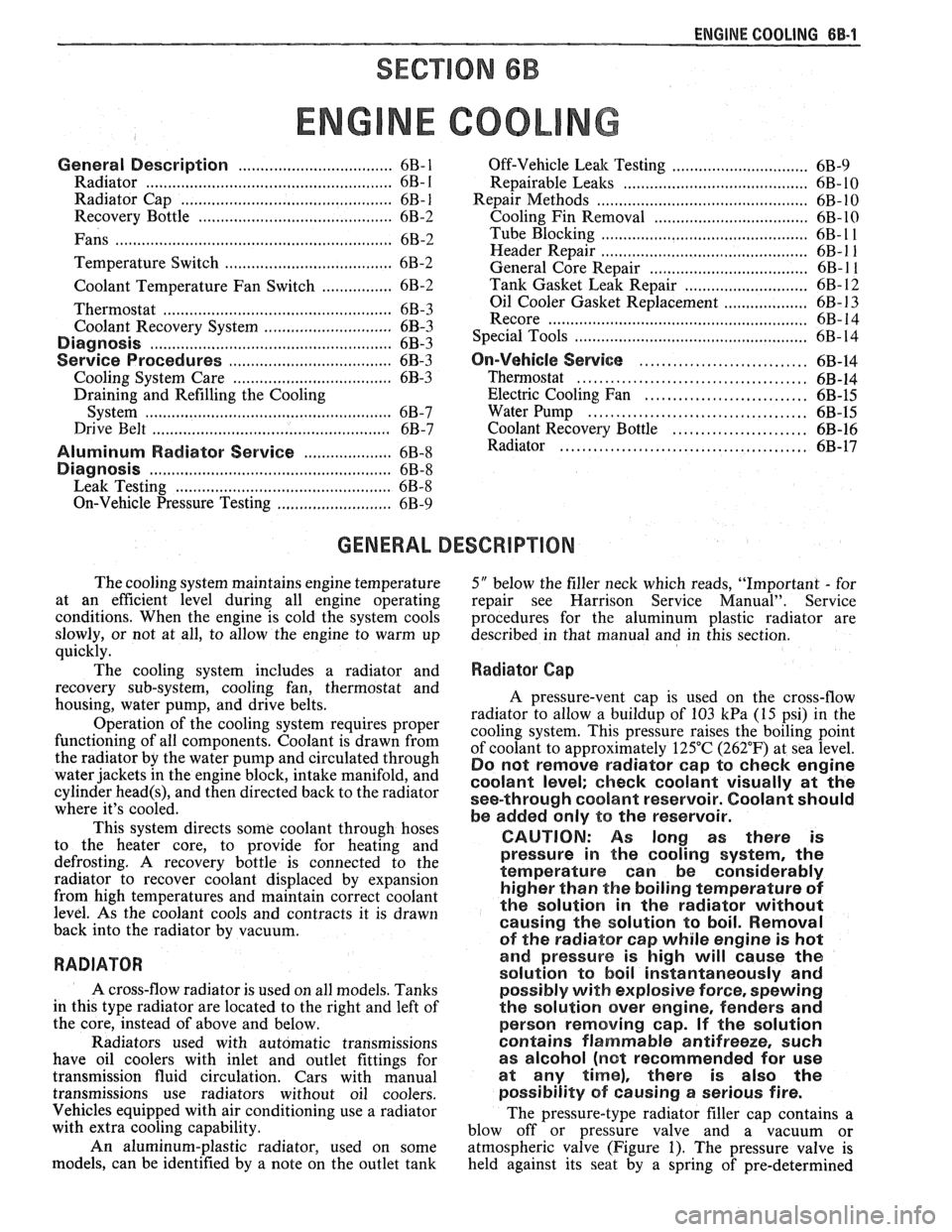
General Description ................................ 6B- 1 Off-Vehicle Leak Testing ............................... 6B-9
Radiator
...................................................... 6B- 1 Repairable Leaks ........................ ... .......... 6B- 10
Radiator Cap
......................... .. ............... 6B- 1 Repair Methods ................................................ 6B- 10
Recovery Bottle ......................................... 6B-2 Cooling Fin Removal ................................ 6B- 10 - ............................................. Fans ............................................................... 6B-2 Tube Blocking 6B- 1 1 ............ Header Repair ....................... .... 6B- 1 1 Temperature Switch ..................................... 6B-2 General Core Repair 6B- 1 1 ....................................
........................... Coolant Temperature Fan Switch ................ 6B-2 Tank
Gasket ~eik Repair 6B- 12
................... Thermostat .. 6B-3 Oil
Cooler Gasket Replacement
6B- 13 ............... ................................
...........................................................
Coolant Recovery System 6B-3 Recore 6B- 14 ............................. Special Tools ..................................................... 6B- 14 Diagnosis ..................................................... 6B-3
.............................. ..................................... Service Procedures 6B-3 On-Vehicle Service 6B-14
Cooling System Care
............................... 6B-3 Thermostat ....................................... 6B-14
Draining and Refilling the Cooling Electric Cooling Fan ............................. 6B-15
System
................................................... 6B-7 Water Pump .................... .... ......... 6B-15
Drive Belt
...................... .. .......................... 6B-7 Coolant Recovery Bottle ........................ 6B-16
.......................................... Aluminum Radiator Service .................... 6B-8 Radiator 6B-17
Diagnosis .................................................... 6B-8
Leak Testing
.............................................. 6B-8
On-Vehicle Pressure Testing
...................... .... 6B-9
GENERAL DESCRIPnIBN
The cooling system maintains engine temperature
5" below the filler neck which reads, "Important - for
at an efficient level during all engine operating repair see Harrison Service Manual". Service
conditions. When the engine is cold the system cools procedures for the aluminum plastic radiator are
slowly, or not at all, to allow the engine to warm up described in that manual and in this section.
quickly.
The cooling system includes a radiator and
Radiator Cap
recovery sub-system, cooling fan, thermostat and
housing, water pump, and drive belts.
Operation of the cooling system requires proper
functioning of all components. Coolant is drawn from
the radiator by the water pump and circulated through
water jackets in the engine block, intake manifold, and
cylinder
head(s), and then directed back to the radiator
where it's cooled.
This system directs some coolant through hoses
to the heater core, to provide for heating and
defrosting. A recovery bottle is connected to the
radiator to recover coolant displaced by expansion
from high temperatures and maintain correct coolant
level. As the coolant cools and contracts it is drawn
back into the radiator by vacuum.
RADIATOR
A cross-flow radiator is used on all models. Tanks
in this type radiator are located to the right and left of
the core, instead of above and below.
Radiators used with automatic transmissions
have oil coolers with inlet and outlet fittings for
transmission fluid circulation. Cars with manual
transmissions use radiators without oil coolers.
Vehicles equipped with air conditioning use a radiator
with extra cooling capability.
An aluminum-plastic radiator, used on some
models, can be identified by a note on the outlet tank A pressure-vent
cap is used on the cross-flow
radiator to allow a buildup of
103 kPa (15 psi) in the
cooling system. This pressure raises the boiling point
of coolant to approximately 125°C (262°F) at sea level.
Do not remove radiator cap to check engine
coolant level; check coolant visually at the
see-through coolant reservoir. Coolant should
be added only
to the reservoir.
CAUTION: As long as there
is
pressure in the cooling system, the
temperature can be considerably
higher than the boiling temperature
of
the solution in the radiator without
causing the solution to boil. Removal
of the radiator cap while engine is hot
and pressure is high will cause
the
solution to boil instantaneously and
possibly with explosive
force, spewing
the solution over engine, fenders and
person removing cap. If the solution
contains flammable antifreeze, such
as alcohol (not recommended for use
at any time), there is also the
possibility
of causing a serious fire.
The pressure-type radiator filler cap contains a
blow off or pressure valve and a vacuum or
atmospheric valve (Figure
1). The pressure valve is
held against its seat by a spring of pre-determined
Page 418 of 1825
ENGINE COOLING BB-7
NOTICE: If recommended quality antifreeze is
used, supplemental inhibitors or additives claiming
to provide increased cooling capability are not
necessary. They may be detrimental to the efficient
operation of the system, and represent an
unnecessary operating expense.
Every 12 months or 15,000 miles, the cooling
system should be serviced as follows;
1. Wash radiator cap and filler neck with clean
water.
2. Check coolant for proper level and freeze
protection.
3. Pressure test system and radiator cap for proper
pressure holding capacity, 103
kPa (15 psi). If
replacement of cap is required, use the proper cap
specified for car model.
4. Tighten hose clamps and inspect all hoses. Replace
hoses whenever cracked, swollen or otherwise
deteriorated.
5. Clean frontal area of radiator core and air
conditioning condenser.
DRAINING AND REFILLING THE COOLING
SYSTEM
Replace hoses every 24 months or 30,000 miles or
earlier if cracked, swollen or otherwise deteriorated.
Every two years or 30,000 miles, whichever first
occurs, the cooling system should be flushed and
refilled using the following recommended procedure:
1. Remove radiator cap, or thermostat housing cap
(VIN
0, J, R and U), when engine is cool by:
a. Slowly
rotating cap counterclockwise to
detent. (Do not press down while rotating.)
b. Wait until any
residual pressure (indicated
by a hissing sound) is relieved.
c. After all hissing ceases, press down on cap
while continuing to rotate
counterclockwise.
CAUTION: To avoid the danger of
being burned, do not remove radiator
cap while engine and radiator are still
hot. Scalding fluid and steam may be
blown out under pressure.
2. Remove the thermostat by using the wire handle
to lift it out of the housing (VIN
0, J, R and U).
3. With the thermostat removed, reinstall the
thermostat housing cap (VIN
0, J, R and U).
4. Open radiator drain valve and block drain plugs
to drain coolant. On VIN R and
9 (P series)
engines, open coolant pipe plugs.
5. Close valve. Reinstall drain plugs, and add
sufficient water to fill system.
6. Run engine, drain and refill the system, as
described in steps
4 and 5 a sufficient number of
times, until the drained liquid is nearly colorless.
Important
BLOCK DRIVE WHEELS, place
transmission in PARK (automatic
transmission) or NEUTRAL (manual
transmission) and set the parking brake. 7.
Allow system to drain completely. Then close
radiator drain valve tightly, and reinstall block
drain plugs.
8. Remove recovery cap leaving hoses in place.
Remove coolant recovery tank and empty of
fluid. Flush tank with clean water, drain and
reinstall.
9. Add sufficient ethylene glycol coolant, meeting
GM specification 1825-M, to provide the
required freezing and corrosion protection
- at
least 50 percent solution -37°C (-34°F). Fill
radiator to the base of the radiator fill neck and
add sufficient coolant to the recovery tank to
raise level to the "FULL" mark. Reinstall
recovery tank cap.
10. Run engine, with radiator cap or thermostat
housing cap removed, until normal operating
temperature is reached. (Radiator upper hose
becomes hot.)
11. With engine idling, add coolant until level
reaches bottom of filler neck and reinstall cap,
making certain arrows line up with overflow tube.
CAUTION: Under some conditions, the
ethylene glycol in engine coolant is
flammable. To help avoid being
burned when adding coolant, DO NOT
spill
it on the exhaust system or hat
engine parts.
It is the owner's responsibility to keep the freeze
protection at a level appropriate to the
temperatures which may occur in the area of
vehicle operation.
a. Maintain
cooling system freeze protection
at
-37°C (-34"F), to ensure protection
against corrosion and loss of coolant from
boiling, even though freezing temperatures
are not expected.
b. Add ethylene glycol base coolant that meets
GM Specification 1825-M, when coolant
additions are required because of coolant
loss, or to provide additional protection
against
freezing at temperatures lower than
-37°C (-34°F).
NOTICE: Alcohol or methanol base coolants, or
plain water, are not recommended at any time.
DRlVE BELT
NOTICE: Routine inspection of the belt may
reveal cracks in the belt ribs. These cracks will
not impair belt performance and therefore should
not be considered a problem requiring belt
replacement. However, the belt should be
replaced if belt slip occurs or if sections of the
belt ribs are missing.
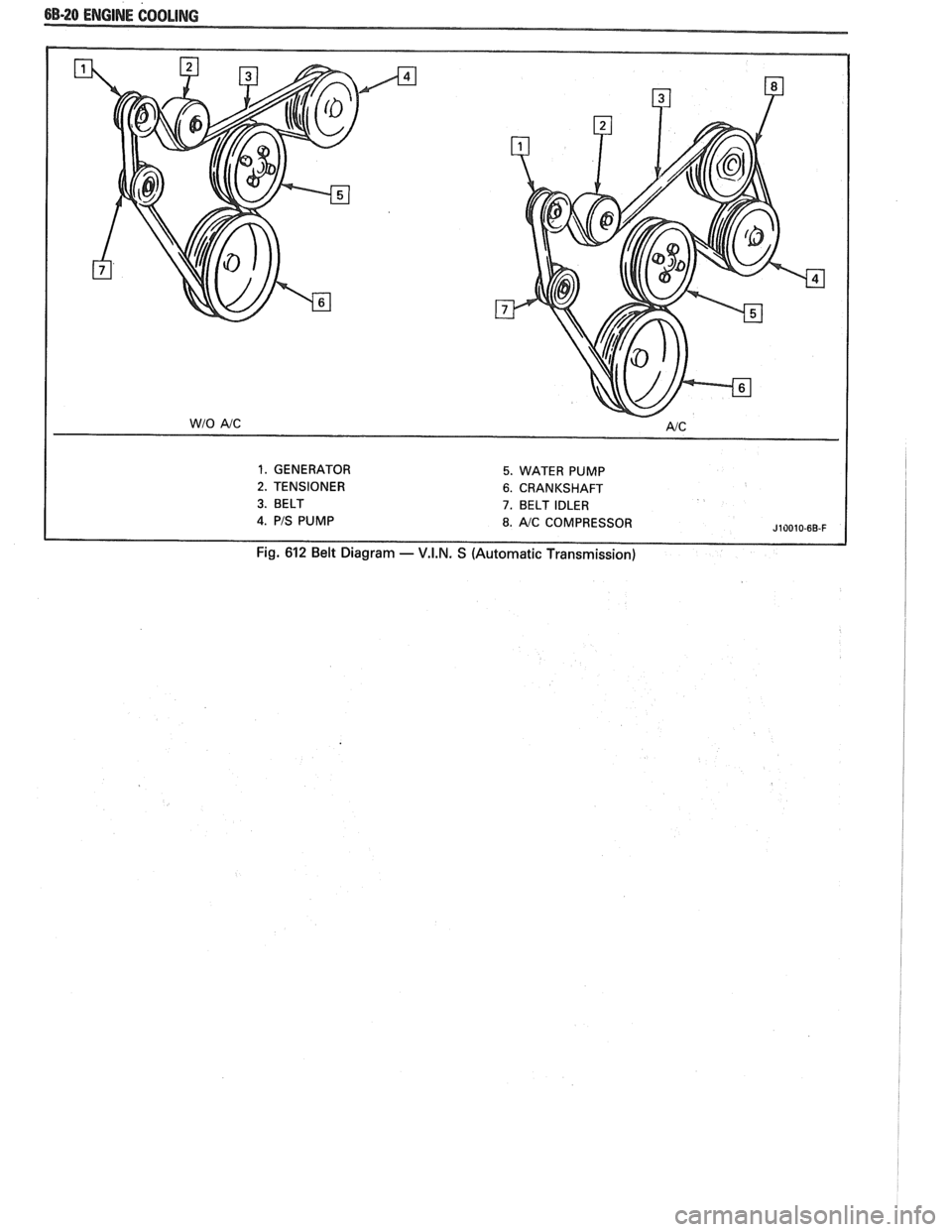
A single (serpentine) belt is used to drive all
engine accessories formerly driven by multiple drive
belts. All belt driven accessories are ridgedly mounted
with belt tension maintained by a spring loaded
tensioner.
The drive belt tensioner has the ability to control
belt tension over a fairly broad range of belt lengths.
Page 428 of 1825
ENGINE COOLING 68.17
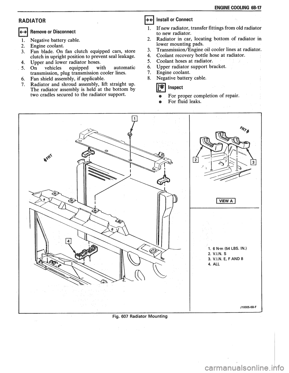
RADIATOR
Remove or Disconnect
1. Negative battery cable.
2. Engine coolant.
3. Fan blade. On fan clutch equipped cars, store
clutch in upright position to prevent seal leakage.
4. Upper and lower radiator hoses.
5. On vehicles equipped with automatic
transmission, plug transmission cooler lines.
6. Fan shield assembly, if applicable.
7. Radiator and shroud assembly, lift straight up.
The radiator assembly is held at the bottom by
two cradles secured to the radiator support.
Install or Connect
1. If new radiator, transfer fittings from old radiator
to new radiator.
Radiator in car, locating bottom of radiator in
lower mounting pads.
Transmission/Engine oil cooler lines at radiator.
Coolant recovery bottle hose at radiator.
Coolant hoses at radiator.
6. Upper radiator support bracket.
7. Engine coolant.
8. Negative battery cable.
Inspect -
e For proper completion of repair.
e For fluid leaks.
Page 431 of 1825
6B-20 ENGINE COOLING
1. GENERATOR 5. WATER PUMP
2. TENSIONER 6. CRANKSHAFT
3. BELT 7. BELT IDLER
J10010-6B-F
Fig. 612 Belt Diagram - V.I.N. S (Automatic Transmission)
Page 447 of 1825
6D1-4 BATTERY
VOLTAGE
A. 16.0 or more
B. 14.0
- 15.9
C. 13.9 or less HOURS
1. Set parking brake and place automatic
Up to 4 Hours transmission in "PARK" (NEUTRAL for
Up to 8 Hours manual transmission.) Turn off the ignition,
Up to 16 Hours turn off lights, and all other electrical
If the charge current is still not
measurable
at the end of the above charging
times, the battery should be replaced.
If the charge current is measurable during
the charging time, the battery is considered to be
good and charging should be completed in the
normal manner.
5. It
is important to remember that a completely
discharged battery must be recharged for a
sufficient number of ampere hours (AH) to
restore it to a usable state. As a general rule of
thumb, using the reserve capacity rating (RC) of
the battery as the number of ampere hours of
charge will usually bring the green dot into view.
For example, if battery is rated at 75 RC minutes,
it would be completely recharged as follows:
10 ampere charge x 7-1/2 hours
= 75 AH
25 ampere charge x 3 hours = 75 AH, etc.
6. It
is recommended that any battery recharged by
this procedure be
LOAD TESTED to establish
serviceability.
JUMP STARTING IN CASE OF EMERGENCY
WITH AUXILIARY (BOOSTER) BAVEEWY
NOTICE: Do not push or tow the vehicle to start.
Damage to the emission system, or to other parts
of the vehicle may result.
Both booster and discharged battery should be
treated carefully when using jumper cables. Follow the
procedure outlined below, being careful not to cause
sparks:
CAUTION: Departure from these
conditions or the procedure below
could result in:
(1) Serious personal
injury (particularly to eyes) or property
damage from such causes as battery
explosion, battery acid, or electrical
burns; and/or
(2) damage to electronic
components of either vehicle.
Never expose battery to open flame or electric
spark
- batteries generate a gas which is flammable and
explosive.
Remove rings, watches, and other jewelry. Wear
approved eye protection.
Do not allow battery fluid to contact eyes, skin,
fabrics, or painted surfaces
- fluid is a corrosive acid.
Flush any contacted area with water immediately and
thoroughly. Be careful that metal tools or jumper
cables do not contact the positive battery terminal (or
metal in contact with it) and any other metal on the
car, because a short circuit could occur. Batteries
should always be kept out of the reach of children.
loads.
2. Check the built-in hydrometer. If it is clear or
light yellow, replace the battery.
3. Attach the end of one jumper cable to the positive
terminal of the booster battery and the other end
of the same cable to the positive terminal of the
discharged battery. Do not permit vehicles to
touch each other as this could cause a ground
connection and counteract the benefits of this
procedure. (Use 12-volt battery only to jump start
the engine).
4. Attach one end of the remaining negative cable
to the negative terminal of the booster battery,
and the other end to a solid engine ground (such
as
A/C compresser bracket or generator
mounting bracket) at least 18 inches from the
battery of the vehicle being started (DO NOT
CONNECT DIRECTLY TO THE NEGATIVE
TERMINAL OF THE DEAD BATTERY).
5. Start the engine of the vehicle that is providing
the jump start and turn off electrical accessories.
Then start the engine in the car with the
discharged battery.
6. Reverse these directions exactly when removing
the jumper cables. The negative cable must be
disconnected from the engine that was jump
started first.
I-FENDER 4-BATTERY (REF.)
2- BOLTISCREW 5-FENDER SKIRT
3-RETAINER
520028-60
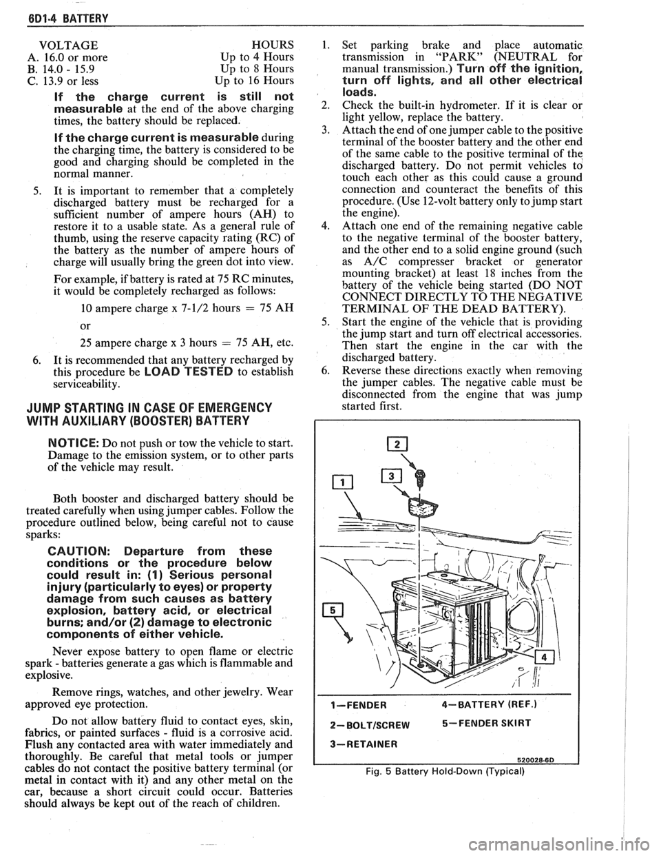
Fig. 5 Battery Hold-Down (Typical)
Page 584 of 1825
DRIVEABILITY AND EMISSIONS - 5.OL (VIN El CEZ-C2-9
u PART IDENTIFICATION NUMBER
VENDOR IDENTlFlCATl
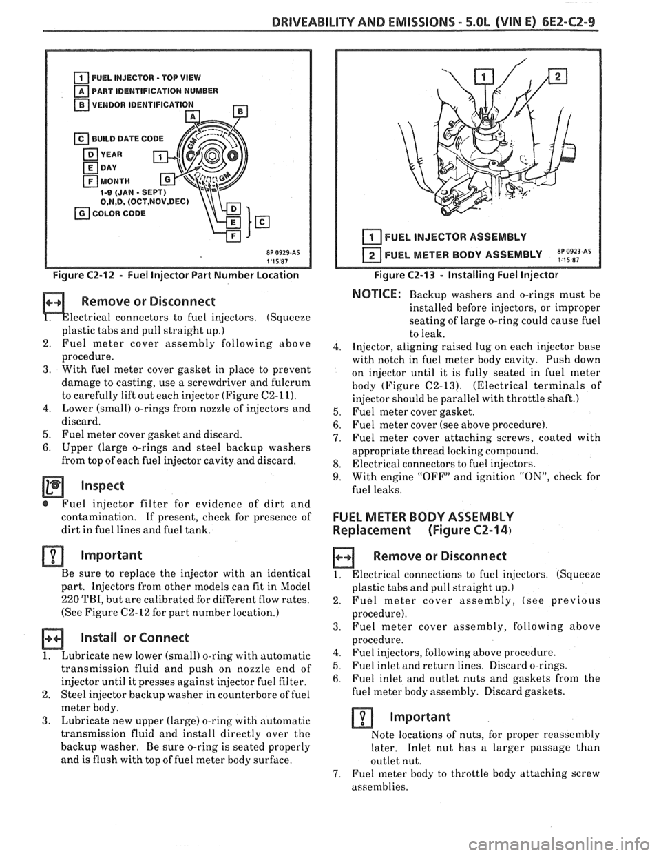
Figure C2-12 - Fuel Injector Part Number Location
Remove or Disconnect
lectrical connectors to fuel injectors. (Squeeze
plastic tabs and pull straight
up.)
2. Fuel meter
cover assembly following above
procedure.
3. With fuel meter cover gasket in place to prevent
damage to casting, use a screwdriver and fulcrum
to carefully lift out each injector (Figure
C2-11).
4. Lower (small) o-rings from nozzle of injectors and
discard.
5. Fuel meter cover gasket and discard.
6. Upper (large o-rings and steel backup washers
from top of each fuel injector cavity and discard.
Inspect
@ Fuel injector filter for evidence of dirt and
contamination.
If present, check for presence of
dirt in fuel lines and fuel tank.
Important
Be sure to replace the injector with an identical
part. Injectors from other models can fit in Model
220 TBI, but are calibrated for different flow rates.
(See Figure
C2-12 for part number location.)
Install or Connect
1. Lubricate new lower (small) o-ring with automatic
transmission fluid and push on nozzle end of
injector until it presses against
in,jector fuel filter.
2. Steel injector backup washer in counterbore of fuel
meter body.
3. Lubricate new upper (large) o-ring with automatic
transmission fluid and install directly over
the
backup washer. Be sure o-ring is seated properly
and is flush with top of fuel meter body surface.
I I 1 I FUEL INJECTOR ASSEMBLY
FUEL METER BODY ASSEMBLY
~p,~9~~~As
Figure C2-13 - Installing Fuel Injector
NOTICE: Backup washers and o-rings must be
installed before injectors, or improper
seating of large o-ring
could cause fuel
to leak.
4. Injector, aligning raised lug on each injector base
with notch in fuel meter body cavity. Push down
on injector until it is fully seated in fuel meter
body (Figure
C2-13). (Electrical terminals of
injector should be parallel with throttle shaft.)
5. Fuel meter cover gasket.
6. Fuel meter cover (see above procedure).
7. Fuel meter cover attaching screws, coated with
appropriate thread locking compound.
8. Electrical connectors to fuel injectors.
9. With engine "OFF" and ignition "ON", check for
fuel leaks.
FUEL METER BODY ASSEMBLY
Replacement (Figure
CZ-14)
a Remove or Disconnect
1. Electrical connections to fuel injectors. (Squeeze
plastic tabs and pull straight up.)
2. Fuel meter cover assembly, (see previous
procedure).
3. Fuel
meter cover assembly, following above
procedure.
4. Fuel injectors, following above procedure.
5. Fuel inlet and return lines. Discard o-rings.
6. Fuel inlet and outlet nuts and gaskets from the
fuel meter body assembly. Discard gaskets.
Important
Note locations of nuts, for proper reassembly
later. Inlet nut has a larger passage than
outlet nut.
7. Fuel meter body to throttle body attaching screw
assemblies.
Page 627 of 1825
6Ef-C8-2 BRlVEABlLlYV AND EMISSIONS - 5.OL (VIN E) ----
RESULTS OF INCORRECTTCC OPERATION
An engine stall will result if the converter clutch
remains applied at all times.
If the converter clutch does not apply, fuel
economy may be lower than expected.
The transmission converter clutch
(TCC) system
has different operating characteristics than an
automatic transmission without TCC.
If the driver
complains of a "chuggle" or "surge" condition, the car
should be road tested and compared to a similar car to
see if a real problem exists. Another TCC complaint
may be
a downshift felt when going up a grade,
especially with cruise control. This may not be
a
downshift, but a clutch disengagement due to the
change in TPS to maintain cruising speed. The
Owner's Manual section on TCC operation should be
reviewed with the driver.
DIAGNOSIS
The diagnosis of the TCC system is covered in
ClIART C-8. If the ECM detects a problem in the VSS
system, a Code
24 should set. In this case see Code 24
Chart.
If the ECM doesn't switch the TCC "ON" when
driving, but will turn it
"ON" when the "test"
terminal is grounded with ignition "ON" and engine
stopped, the sensors such as coolant, speed, and
throttle position should be checked.
ON-CAW SERVICE
@ See Section "7" for TCC Solenoid.
@ See Section "SH" for VSS (HP mounted) and brake
system.
PAR- SNFORMATBIQN
PART NAME GRQUQ
.......................... Sensor, VSS 9.761
........................ Solenoid, TCC 4.122
Page 629 of 1825
6EZ-C8-4 DRIVEABILITY AND EMISSIONS - 5.OL (VIN E)
I5 WAY (FRONT VIEW)
SPEED INPUT
4rH GEAR SIGNAL
422 TANIBLK
ALDL CONNECTOR
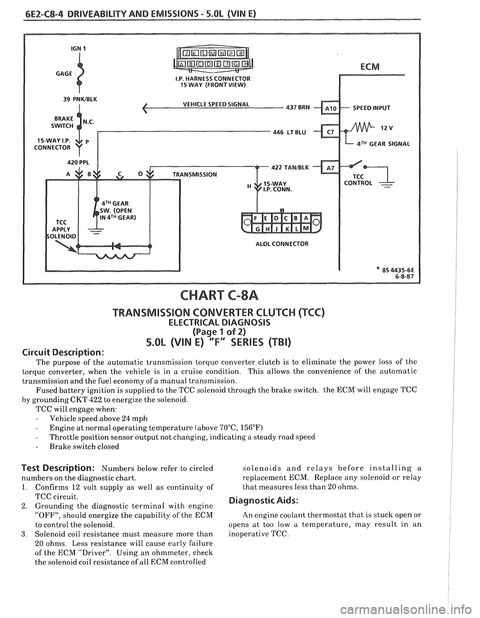
CHART C-8A
TRANSMISSION CONVERTER CLUTCH (TCC)
ELECTRICAL DIAGNOSIS
(Page 1 of 2)
5.OL (VIN E) "F" "SERIES (TBI)
Circuit Description:
The purpose of the automatic transmission torque converter clutch is to eliminate the power loss of the
torque converter, when the vehicle is in a cruise condition. This allows the convenience of the automatic
transmission and the fuel economy of a manual transmission.
Fused battery ignition is supplied to the TCC solenoid through the brake switch. the ECM will engage
TCC
by grounding CKT 422 to energize the solenoid.
TCC will engage when:
- Vehicle speed above 24 mph - Engine at normal operating temperature (above 70°C, 156°F)
- Throttle position sensor output not changing, indicating a steady road speed
- Brake switch closed
Test Description: Numbers below refer to circled solenoids
and relays before installing a
numbers on the diagnostic chart. replacement ECM. Replace
any solenoid or relay
1. Confirms 12 volt supply as well as continuity of that
measures less than 20 ohms.
TCC circuit.
2. Grounding the diagnostic terminal with engine Diagnostic Aids:
"OFF", should energize the capability of the ECM An
engine coolant thermostat that is stuck open or
to control the solenoid. opens
at too low a temperature, may result in an
3. Solenoid coil resistance must measure more than inoperative TCC.
20 ohms. Less resistance will cause early failure
of the ECM
drive^.". Using an ohmmeter, check
the solenoid coil resistance of
all ECM controlled
Page 642 of 1825
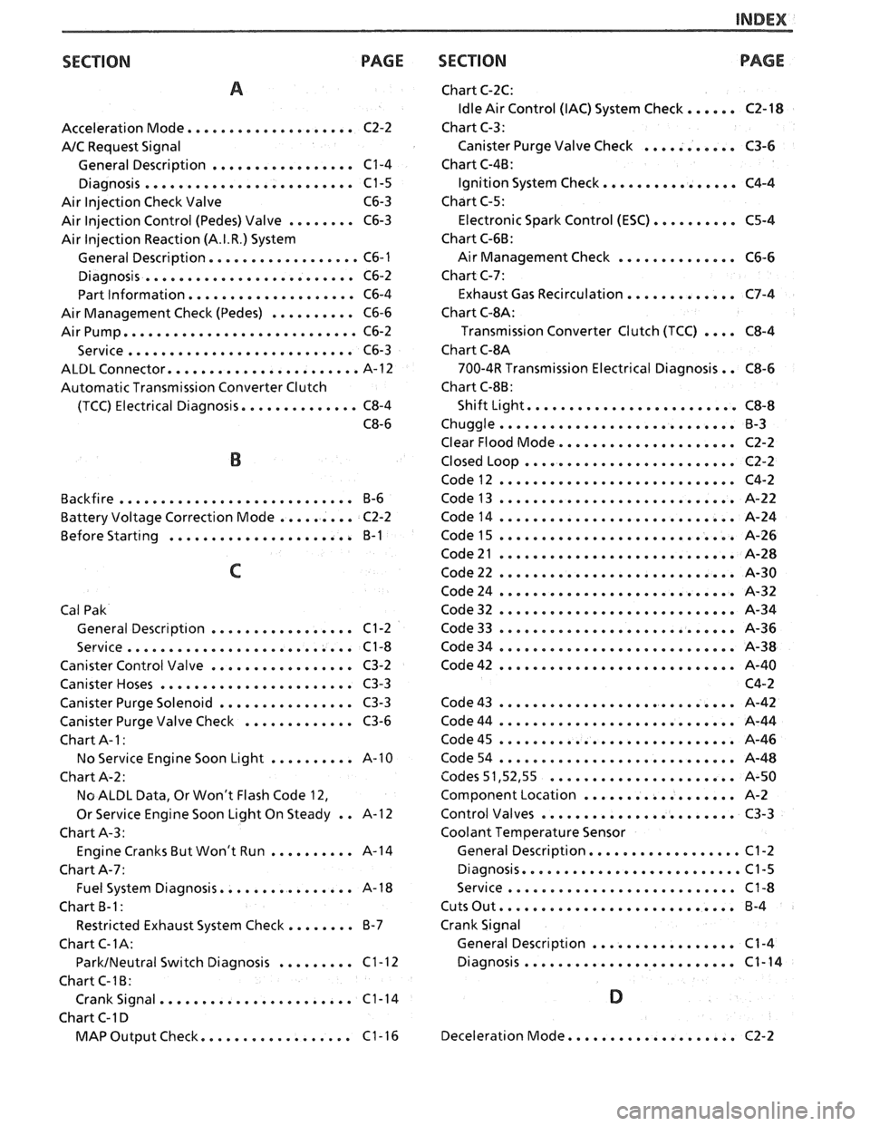
SECTION PAGE
A
Acceleration Mode .................... C2-2
AIC Request Signal
General Description
................. C1-4
Diagnosis ......................... C1-5
Air Injection Check Valve C6-3
Air Injection Control (Pedes) Valve
........ C6-3
Air
lnjection Reaction (A.I.R.) System
General Description
.................. C6- 1
Diagnosis ......................... C6-2
Part Information
.................... C6-4
Air Management Check (Pedes)
.......... C6-6
Air Pump
............................ C6-2
........................... Service C6-3
ALDL Connector ....................... A-1 2
Automatic Transmission Converter Clutch
(TCC) Electrical Diagnosis
.............. C8-4
C8-6
B
Backfire ............................ 6-6
......... Battery Voltage Correction Mode C2-2
Before
Start~ng ...................... B-1
C
Cal Pak General
Descript~on ................. C1-2
Service
........................... C1-8
Canister Control Valve
................. C3-2
Canister Hoses
....................... C3-3
Canister Purge Solenoid
................ C3-3
Canister Purge Valve Check
............. C3-6
Chart A-
I :
No Service Engine Soon Light .......... A-10
Chart A-2:
No ALDL Data. Or Won't Flash Code 12.
Or Service Engine Soon Light On Steady
. . A-1 2
Chart A-3:
Engine Cranks But Won't Run
.......... A-14
Chart A-7:
Fuel System Diagnosis
................ A-1 8
Chart
B-1:
Restricted Exhaust System Check ........ 6-7
Chart C-IA:
ParkINeutral Switch Diagnosis ......... Cl-12
Chart C-16:
Crank Signal
....................... C1-14
Chart C-1 D
.................. MAP Output Check C1-16
SECTION
Chart C-2C:
Idle Air Control (IAC) System Check ...... C2-18
Chart C-3:
Canister Purge Valve Check
........... C3-6
Chart C-4B:
Ignition System Check
................ C4-4
Chart C-5:
Electronic Spark Control
(ESC) .......... C5-4
Chart C-66:
Air Management Check
.............. C6-6
Chart C-7:
Exhaust Gas Recirculation
............. C7-4
Chart
C-$A:
Transmission Converter Clutch (TCC) .... C8-4
Chart
C-8A
700-4R Transmission Electrical Diagnosis . . C8-6
Chart
C-86:
Shift Light ......................... C8-8
Chuggle
............................ B-3
Clear Flood Mode
..................... C2-2
Closed Loop
......................... C2-2
Code12
............................ C4-2
Code13
............................ A-22
Code14
............................ A-24
Code43
............................ A-42
Code44
............................ A-44
Code45
............................ A-46
Code54
............................ A-48
Codes 5 1.52. 55
...................... A-50
Component Location
.................. A-2
Control Valves
....................... C3-3
Coolant Temperature Sensor
General Description
.................. C1-2
Diagnosis
.......................... Cl-5
Service
........................... C1-8
Cuts Out ............................ 6-4
Crank Signal General Description
................. C1-4
Diagnosis
......................... C1-14
D
Deceleration Mode .................... C2-2
Page 647 of 1825
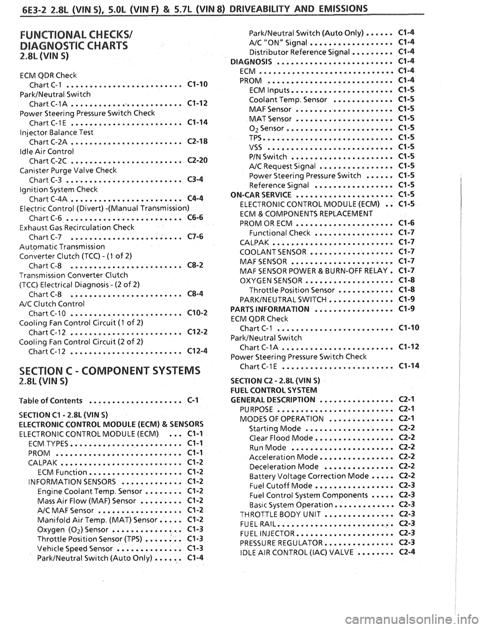
FUNCTIONAL CHECKS/
DIAGNOSTIC CHARTS
2.8L (VIN S)
ECM QDR Check
......................... Chart C-1 C1-10
ParkINeutral Switch
......................... Chart C-1A C1-12
Power Steering Pressure Switch Check
........................ ChartC-1E C1-14
Injector Balance Test
........................ Chart C-2A C2-18
Idle Air Control
........................ Chart C-2C C2-20
Canister Purge Valve Check
......................... Chart C-3 C3-4
Ignition System Check
........................ Chart C-4A C4-4
Electr~c Control (Divert) -(Manual Transmission)
......................... Chart C-6 C6-6
Exhaust Gas Recirculation Check
........................ Chart C-7 C7-6
Automatic Transmission
Converter Clutch (TCC)
. (I of 2)
........................ Chart C-8 C8-2
Transmiss~on Converter Clutch
(TCC) Electrical Diagnosis
. (2 of 2)
........................ Chart C-8 C8-4
A/C Clutch Control
........................ Chart C-10 C10-2
Cooling Fan Control Circuit (I of 2)
........................ Chart C-12 C12-2
Cooling Fan Control Circuit (2 of 2)
........................ Chart C-12 C12-4
ParklNeutral Switch (Auto Only) ...... C1-4
AIC "ON" Signal .................. C1-4
Distributor Reference Signal ......... C1-4
......................... DIAGNOSIS C1-4
............................. ECM C1-4
........................... PROM C1-4
...................... ECM Inputs C1-5
Coolant Temp . Sensor ............. C1-5
..................... MAFSensor C1-5
..................... MAT Sensor C1-5
....................... 02Sensor C1-5
TPS ............................ C1-5
........................... VSS C1-5
...................... PIN Switch C1-5
................ A/C Request Signal C1-5
Power Steering Pressure Switch ...... C1-5
................. Reference Signal C1-5
ON-CAR SERVICE ..................... C1-5
ELECTRONIC CONTROL MODULE (ECM) . . C1-5
ECM & COMPONENTS REPLACEMENT
..................... PROM OR ECM C1-6
................. Functional Check C1-7
CALPAK .......................... C1-7
COOLANT SENSOR .................. C1-7
MAFSENSOR ...................... C1-7
MAF SENSOR POWER & BURN-OFF RELAY . C1-7
................... OXYGEN SENSOR C1-8
Throttle Position Sensor ............ C1-8
PARKINEUTRALSWITCH .............. C1-9
................. PARTS INFORMATION C1-9
ECM QDR Check
................... ... Chart C-1 ... C1-10
ParktNeutral Switch
........................ ChartC-1A C1-12
Power Steering Pressure Switch Check
........................ SECTION C . COMPONENT SYSTEMS ChartC-lE C1-14
2.8L (VIN S) SECTION C2 . 2.8L (WIN S)
FUEL CONTROL SYSTEM
................ 'Table of Contents .................... C-1 GENERAL DESCRIPTION C2-1
SECTION
C1 . 2.8L (VIN S)
ELECTRONIC CONTROL MODULE (ECM)
& SENSORS
ELECTRONIC CONTROL MODULE (ECM) ... C1-1
........................ ECM TYPES C1-1
........................... PROM C1-1
CALPAK .......................... C1-2
.................... ECM Function C1-2
............. INFORMATION SENSORS C1-2
Engine Coolant Temp . Sensor ........ C1-2
Mass Air Flow (MAF) Sensor ......... C1-2
.................. A/C MAF Sensor Cl-2
Manifold Air Temp . (MAT) Sensor ..... C1-2
Oxygen (Oz)Sensor ............... C1-3
Throttle Position Sensor (TPS) ........ C1-3
Vehicle Speed Sensor .............. C1-3
ParkINeutral Switch (Auto Only) ...... C1-4
......................... PURPOSE C2-1
.............. MODES OF OPERATION C2-1
................... Starting Mode C2-2
................. Clear Flood Mode C2-2
...................... Run Mode C2-2
................ Acceleration Mode C2-2
............... Deceleration Mode C2-2
Battery Voltage Correction Mode ..... C2-2
................. Fuel Cutoff Mode C2-3
Fuel Control System Components ..... C2-3
Basic System Operat~on ............. C2-3
THROTTLEBODY UNIT ............... C2-3
......................... FUELRAIL C2-3
..................... FUEL INJECTOR C2-3
............... PRESSURE REGULATOR C2-3
IDLE AIR CONTROL (IAC) VALVE ........ C2-4