brake light PONTIAC FIERO 1988 Service User Guide
[x] Cancel search | Manufacturer: PONTIAC, Model Year: 1988, Model line: FIERO, Model: PONTIAC FIERO 1988Pages: 1825, PDF Size: 99.44 MB
Page 255 of 1825
4819 REAR AXLE
bears against the inner race of the front bearing and a
shoulder on the pinion stem. This spacer is used to
enable accurate bearing pre-load adjustment and
maintain a pre-load on both front and rear pinion
bearings, Adjustment of the fore and aft position of the
pinion is obtained by placing a shim between the rear
pinion bearing cup and axle housing. The differential
case is of two-piece construction and is supported in
the carrier by two tapered roller side bearings. Pre-load
rear axle case by inserting shims between the bearings
and the carrier. The rear axle case assembly is
positioned for proper ring gear to pinion backlash by
varying the shim thickness from side to side. The ring
gear is bolted to the case. Two side gears have splined
bores for driving the axle shafts. They are positioned
to turn in counterbored cavities in the case. The four
rear axle pinions have smooth bores and are held in
position by a pinion cross shaft, mounted and locked
in the rear axle case. All six gears are in mesh with each
other and because the pinion gears turn freely on their
shaft, they act as idler gears when the rear wheels are
turning at different speeds. The pinions and side gears
are backed by steel thrust washers.
LIMITED-SLIP REAR AXLE
The operation of the Limited-Slip differential is
the same as the standard differential, except that there
is additional friction provided by the conical clutches.
Under ordinary driving and cornering conditions, the
cones slip, allowing the outside wheel to turn faster
than the inner. Under poor traction conditions, such as
ice, snow, or loose gravel under one driving wheel, the
increased friction provided by the cones increases the
driving torque available to the wheel with the better
traction. The cones are spring loaded to provide the
increased driving torque under extremely low traction
conditions.
Operation
When the vehicle turns a corner, the outer rear
wheel must turn faster than the inner wheel. The inner
wheel, turning slower than the outer wheel, slows its
differential side gear (as the axle shaft is splined to the
side gear) and the differential pinion gears will roll
around the slowed differential side gear, driving the
other differential side gear and wheel faster.
DIAGNOSIS AND TESTING
Many noises reported as coming from the rear
axle assembly actually originate from other sources
such as tires, road surfaces, front wheel bearings, axle
bearing, engine, transmission, muffler or body
drumming. A thorough and careful check should be
made to determine the source of the noise before
disassembling the rear axle. Noise which originates in
other places cannot be corrected by adjustment or
replacement of parts in the differential. It should also
be remembered that rear axle gears, like any other
mechanical device, are not absolutely quiet and should
be accepted as being commercially quiet unless some
abnormal noise is present.
To make a systematic check for axle noise under
standard conditions, observe the following:
1. Select a level smooth asphalt road to reduce tire
noise and body drumming.
2. Check rear axle lubricant to assure correct level,
then drive car far enough to thoroughly warm up
rear axle lubricant, approximately 10 miles.
3. Note speed and RPM at which noise occurs. Stop
car and put transmission in neutral. Run engine
slowly up and down through engine speeds,
corresponding to car speed at which noise was
most pronounced, to determine if it is caused by
exhaust, muffler roar or other engine conditions.
4. Tire noise changes with different road surfaces,
but rear axle noise does not. Temporarily
inflating all tires to approximately 50 pounds
pressure
for test purposes only will materially
alter noise caused by tires, but will not affect noise
caused by rear axle. Rear axle noise usually stops
when coasting at speeds under 30 miles per hour;
however, tire noise continues, but with lower
tone, as car speed is reduced. Rear axle noise
usually changes when comparing acceleration
and coast, but tire noise remains about the same.
Distinguish between tire noise and rear axle noise
by noting if noise varies with various speeds or
sudden acceleration and deceleration; exhaust
and axle noise show variations under these
conditions while tire noise remains constant and
is more pronounced at speeds of 20 to 30 miles
per hour. Further check for tire noise by driving
car over smooth pavements or dirt roads (not
gravel) with tires at normal pressure. If noise is
caused by tires, it will noticeably change or
disappear and reappear with changes in road
surface.
5. Loose or rough front wheel bearings will cause
noise which may be confused with rear axle
noises; however, front wheel bearing noise does
not change when comparing drive and coast.
Light application of brakes while holding car
speed steady will often cause wheel bearing noise
to diminish, as this takes some weight off the
bearing. Front wheel bearings may be easily
checked for noise by jacking up the wheels and
spinning them, also by shaking wheels to
determine if bearings are loose.
6. Rear suspension rubber bushings and spring
insulators dampen out rear axle noise when
correctly installed. Check to see that no metallic
contact exists between the spring and spring seat
opening in frame or between upper and lower
control arm bushings and frame or axle housing
brackets. The track bar and torque arm must be
bolted securely. Metal-to-metal contact at those
points may result in telegraphing road noise and
normal axle noise which would not be
objectionable if dampened by bushings.
AXLE NOISES
After the noise has been determined as being in
the axle by following the above appraisal procedure,
the type of axle noise should be determined to aid in
making repairs if necessary.
Page 257 of 1825
481-4 REAR AXLE
Gear Noise
Gear noise (whine) is audible from 20 to 55 mph
under four driving conditions:
1. Light Acceleration - Accelerate slowly.
2. Road Load
- Car
driving load or constant speed.
3. Float - Using enough throttle to keep the car from
driving the engine
- car slows down gradually but
engine still pulls slightly.
4. Coast - Throttle closed and car in gear.
Bearing Noise
Bad bearings generally produce more of a rough
growl or grating sound, rather than the whine typical
of gear noise. Bearing noise frequently "wow-wows" at
bearing rpm, indicating a defective pinion or rear axle
case side bearing. This noise could easily be confused
with rear wheel bearing noise. Inspect and replace as
required.
Rear Wheel Bearing Noise
A rough rear wheel bearing produces a noise
which continues with car coasting at low speed and
transmission in neutral. Noise may diminish some by
gentle braking. With rear wheels jacked up, spin rear
wheels by hand while listening at hubs for evidence of
rough (noisy) wheel bearing.
Knock At Low Speeds
Low speed knock can be caused by worn
universal joints or a side gear hub counterbore in a case
that has worn oversize. Inspect and replace universal
joint or case and side gear as required.
Backlash Clunk
Excessive clunk with acceleration and deceleration
is caused by worn differential pinion gear shaft, excessive
clearance between axle shaft and side gear splines, exces-
sive clearance between side gear hub and counterbore in
case, worn pinion and side gear teeth, worn thrust washers
and excessive drive pinion and ring gear backlash. Re-
move worn parts and replace as required, selecting close
fitting parts when possible. Adjust pinion and ring gear
backlash.
DIAGNOSIS
1. Noise
is the same in "Light Acceleration" or
"Coast".
a. Road noise.
b. Tire noise.
c. Front wheel bearing noise.
d. Rear axle bearing noise.
2. Noise changes on a different type of road.
a. Road noise.
b. Tire noise.
3. Noise tone lowers as car speed is lowered.
a. Tire noise.
b. Front
wheel bearings and rear axle bearings.
c. Gear noise.
4. Similar noise is produced with car standing and
driving. a.
Engine noise.
b. Transmission noise.
c. Exhaust noise.
5. Vibration.
a. Rough rear axle bearing.
b. Unbalanced or damaged propeller shaft.
c. Tire unbalance.
d. Worn universal joint in propeller shaft.
e. Mis-indexed propeller shaft at pinion
flange.
f. Pinion flange runout too great.
6. A knock or click approximately every two
revolutions of the rear wheel.
a. A rear axle bearing.
b. Worn case.
7. Noise most pronounced on turns.
a. Rear axle side gear and pinion noise,
differential gear noise.
b. Axle bearings.
8. A continuous low pitch whirring or scraping
noise starting at relatively low speed.
a. All bearing noise.
9. Drive noise, coast noise or float noise.
a. Ring
and pinion gear noise.
b. Front
pinion bearing noise, coast or drive.
c. Axle bearing noise.
10. Clunk
on
acceleration or deceleration.
a. Worn
rear axle pinion shaft splines.
b. Side
gear hub counterbore in case worn
oversize.
c. Worn U-joints.
d. Excessive transmission backlash.
e. Worn axle shaft splines.
11. Chatter on turns.
a. Wrong
lube in rear axle.
b. Clutch
cone worn or spalled.
12. Clunk
or knock on rough road operation.
a. Worn suspension bushings.
PRE-REPAIR INVESTIGATION AND TROUBLE
DIAGNOSIS
A carefull diagnosis of the rear axle prior to
disassembly will often reveal valuable information as to
the extent and type of repairs or adjustments necessary.
Since frequent causes of axle noises are improper
backlash, pinion bearing pre-load, or side bearing
pre-load, or a combination, a few simple adjustments
may be all that are necessary to correct a problem.
Before disassembling the rear axle, the following
checks should be made with the results recorded and
analyzed: 1) Backlash;
2) Total Assembly Preload; 3)
Tooth Contact Pattern Test; 4) Fluid Level; and 5)
Fluid Contamination.
If axle shaft end play is excessive then check
bearings, retainer, and bolts securing backing plate.
The axle bearings could be worn and need replacement.
The four bolts or nuts securing the brake backing plate
may be loose, stripped, or missing. If the inner bearing
retainer worked loose it must be replaced.
Use care at all times to keep dirt and other foreign
matter, such as grinder dust, soot or sand, away from
differential to prevent possibility of subsequent failure.
Page 260 of 1825
REAR AXLE 481-7
ON-VEHICLE SERVICE
CARRIER COVER AND GASKET
Remove or Disconnect
1. Having
a container in place remove drain plug
with tool
J-35117,remove cover bolts and pry
cover loose to drain lubricant.
2. Make sure both
gasket sealing surfaces are clean.
Install or Connect
Use cover gasket (do not assemble with
sealant alone).
NOTICE: Apply locktite part No. 573, GM Part
Nos. 1052080, or 1052279 or equivalent to cover
bolts before installing cover. If sealant is not applied
bolts may loosen causing fluid leak and damage to
rear axle assembly.
1. Torque cover bolts in a crosswise pattern to
insure uniform draw on gasket. Torque
26 N.m
(20 1b.ft.).
2. Fill with lubricant to bottom of filler plug hole.
Refer to specifications for correct lubricant usage
and quantity.
AXLE SHAFT
Remove or Disconnect
1. Wheel
and brake components as necessary.
2. The
four nuts holding the brake anchor plate and
outer bearing retainer.
3. Withdraw the axle shaft and wheel bearing assem-
bly using axle shaft remover
J 21579 and slide
hammer
J 2619-01 (Fig. 4).
Fig. 4 Axle Shaft Removal
4. Inner
bearing retainer and bearing from axle
shaft. To do this carefully split the retainer with
a chisel and remove from shaft. Press off bearing
with tool
5-22912-01 from axle. Discard bearing
and seal (Fig. 5).
Fig. 5 Bearing and Seal Removal
Examine axle shaft. If axle shaft is in satisfactory
condition it may be re-used.
Important
Bearings and inner bearing retainers which
have been removed from an axle shaft
should not be re-used.
Install or Connect
1. Place the outer bearing retainer on the axle shaft.
Important
Right and left hand axle shaft seals are
different in construction. Right hand seal is
black banded with right hand ridges. Left
hand seal is gold banded with left hand
ridges. The part numbers designate left and
right sides.
2. Place the oil seal on the axle shaft ensuring that
the spring side of the oil seal faces the center of
the axle. Lubricate seals lips with a light coat of
grease. Note use of excessive amounts of grease
may damage seal.
3. Press wheel bearing and inner bearing retainer hard
against bearing shoulder on axle shaft with tool
J 8853-01, ensuring that the retainer is tight against
the bearing and with
O.D. chamfer towards
bearing.
4. Place the axle shaft through the brake anchor
plate and align axle shaft and side gear splines.
5. Once the splines have been engaged in the side
gears the wheel bearing and oil seal may be
pushed into the housing.
A light coat of grease on
the seal outside diameter will assist in installation.
Tighten four backing plate bolts alternately. Use
new locknuts on bolts. (Refer to specifications).
NOTICE: If a limited-slip differential is used
ensure that both axle shaft splines are fully
engaged before the axle shafts are rotated. This is
to mainatain spline alignment, refer to limited-slip
instructions.
Page 261 of 1825
481.8 REAR AXLE
6. Replace
brake components and wheel.
7. Tighten wheel nuts and lower vehicle.
Tooth Contact Pattern Test
The side of the ring gear tooth which curves
outward, or is convex, is referred to as the "drive" side.
The concave side is the "coast" side. The end of the
tooth nearest center of ring gear is referred to as the
"toe" end. The end of the tooth farthest away from the
center is the "heel" end. Toe end of tooth is smaller
than heel end.
It is very important that tooth contact be tested
before the rear axle carrier assembly is disassembled.
Variations in the carrier or pinion rear bearing may
cause the pinion to be too far away from, or close to,
the ring gear. Thus, the tooth contact must be tested
and corrected, if necessary, or the gears may be noisy.
Procedure
1. Drain
oil out of carrier and carefully clean each
tooth of ring gear.
2. Apply parking brake until a torque of 54 to 70
N-m (40-50 lb. ft.) is required to turn the pinion.
3. Tighten bearing cap bolts to 52 N-m (40 lb. ft.).
4. Use gear marking compound part number
1052351 or equivalent and apply this mixture
sparingly to all ring gear teeth, using a medium
stiff brush. When properly used, the area of
pinion tooth contact will be visible when hand
load is applied.
A test made without loading the gears will not
give a satisfactory pattern. Turn pinion flange
with wrench so that ring gear rotates five full
revolutions, then reverse rotation so that ring
gear rotates five
revolutio~ls in opposite direction.
5. Observe pattern on ring gear teeth and compare
with Fig.
6.
Effects of Increasing Load on Teeth Contact
Pattern
When "load" on ring and pinion gear is
increased, such as when car is accelerated forward
from standstill or from normal drive, the tooth contact
will tend to spread out and, under very heavy load, will
extend from near toe to near heel on the drive side. The
entire contact also tends to shift toward heel under
increasingly heavier loads and will become somewhat
broader with respect to tops and bottoms of teeth. The
patterns obtained by this tooth contact pattern test
approximate a light load and, for this reason, they will
extend only about halfway.
The important thing to note is that the contact
pattern is centrally located up and down on the face of
the ring gear teeth.
Adjustments Affecting Tooth Contact
Two adjustments can be made which will affect
tooth contact pattern, backlash and position of drive
pinion in carrier. The effects of bearing pre-loads are
not readily apparent
on (hand-loaded) tooth contact
pattern tests; however, these adjustments should be within
specifications before proceeding with backlash
and drive pinion adjustments.
Backlash is adjusted by means of the side bearing
adjusting shims, which moves the entire case and ring
gear assembly closer to, or farther from, the drive
pinion (the adjusting shims are also used to set side
bearing pre-load). The position of the drive pinion is
adjusted by increasing or decreasing the shim thickness
between the rear pinion cup and axle housing
. The
shim is used in the rear axle case to compensate for
manufacturing tolerances. Increasing shim thickness
will move the pinion closer to centerline of the ring
gear. Decreasing shim thickness will move pinion
farther away from centerline of the ring gear.
Effects of Pinion Position on Tooth Pattern
When the drive pinion is too far away from
centerline of the ring gear, the pattern will be a high
heel contact on the drive side and high toe contact on
coast side (Fig. 6). Moving the pinion closer to
centerline of the ring gear by increasing shim thickness
will cause the high heel contact on drive side to lower
and move toward the toe; the high toe contact on coast
side will lower and move toward the heel.
When the pinion is too close to the centerline of
the ring gear, the pattern will be a low toe contact on
drive side and a low heel contact on the coast side.
Moving the pinion farther away from the ring gear by
decreasing shim thickness will cause low toe contact on
drive side to raise and move toward the heel; the low
heel contact on coast side will raise and move toward
the toe.
PINION OIL SEAL AND COMPANION FLANGE
REPLACEMENT
Remove or Disconnect
1. Mark the propeller shaft and companion flange
so they can be reassembled in the same position.
Remove four nuts and lock washers from two
saddles retaining
U-joints to companion flange
and remove propeller shaft.
2. Measure and record preload at pinion - this
includes pinion bearing, differential bearings,
effect of grease and oil seal. (Figure
7).
3. Pinion nut with companion flange remover
J-8614-01. (Figure 8).
4. Companion flange with companion flange
remover
5-8614-01. (Figure 8).
5. Seal and discard.
NOTICE: Before installing a new seal examine the
surface of the companion flange on which the seal
runs. Should this surface be damaged or the splines
excessively worn, a new companion flange should
be installed. Also examine the housing bore and
remove any nicks or burrs.
Page 276 of 1825
REAR AXLE 4B-3
Noise which originates in other places cannot be
corrected by adjustment or replacement of parts in the
differential. It should also be remembered that rear
axle gears, like any other mechanical device, are not
absolutely quiet and should be accepted as being
commercially quiet unless some abnormal noise is
present.
To make a systematic check for axle noise under
standard conditions, observe the following:
1. Select a level smooth asphalt road to reduce tire
noise and body drumming.
2. Check rear axle lubricant to assure correct level,
then drive car far enough to thoroughly warm up
rear axle lubricant.
3. Note speed and RPM at which noise occurs. Then
stop car and with automatic transmission in neutral,
run engine slowly up and down through engine speeds, corresponding to car speed at which noise
was most pronounced, to determine if it is caused by
exhaust, muffler roar or other engine conditions.
4. Tire noise changes with different road surfaces,
but rear axle noise does not. Temporarily
inflating all tires to approximately 50 pounds
pressure for
test purposes only will materially
alter noise caused by tires, but will not affect noise
caused by rear axle. Rear axle noise usually stops
when coasting at speeds under 30 miles per hour;
however, tire noise continues, but with lower
tone, as car speed is reduced. Rear axle noise
usually changes when comparing acceleration
and coast, but tire noise remains about the same.
Distinguish between tire noise and rear axle noise
by noting if noise varies with various speeds or
sudden acceleration and deceleration; exhaust
and axle noise show variations under these
conditions while tire noise remains constant and
is more pronounced at speeds of 20 to 30 miles
per hour. Further check for tire noise by driving
car over smooth pavements or dirt roads (not
gravel) with tires at normal pressure. If noise is
caused by tires, it will noticeably change or
disappear and reappear with changes in road
surface.
5. Loose or rough front wheel bearings will cause
noise which may be confused with rear axle
noises; however, front wheel bearing noise does
not change when comparing drive and coast.
Light application of brakes while holding car
speed steady will often cause wheel bearing noise
to diminish, as this takes some weight off the
bearing. Front wheel bearings may be easily
checked for noise by jacking up the wheels and
spinning them, also by shaking wheels to
determine if bearings are loose.
6. Rear suspension rubber bushings and spring
insulators dampen out rear axle noise when
correctly installed. Check to see that no metallic
contact exists between the spring and spring
opening in frame or between upper and lower
control arm bushings and frame or axle housing
brackets.
Metal-to-metal contact at those points
may result in telegraphing road noise and normal axle
noise which would not be objectionable if
dampened by bushings.
AXLE NOISES
Gear Noise
After the noise has been determined as being in
the
axle by following the above appraisal procedure,
the type of axle noise should be determined to aid in
maki~~g repairs if necessary.
Gear noise (whine) is audible from 20 to
55 mph
under four driving conditions:
1. Drive - Acceleration or heavy pull.
2. Road Load - Car driving load or constant speed.
3. Float
- Using
enough throttle to keep the car from
driving the engine
- car slows down gradually but
engine still pulls slightly.
4. Coast
- Throttle closed and car in gear. Gear
noise most frequently has periods where noise is
more prominent, usually 30 to 40 mph and 50 to
55 mph.
Bearing Noise
Bad bearings generally produce more of a rough
growl or grating sound, rather than the whine typical
of gear noise. Bearing noise frequently "wow-wows" at
bearing rpm, indicating a defective pinion or rear axle
case side bearing. This noise could easily be confused
with rear wheel bearing noise. Inspect and replace as
required.
Rear Wheel Bearing Noise
A rough rear wheel bearing produces a noise
which continues with car coasting at low speed and
transmission in neutral. Noise may diminish some by
gentle braking. With rear wheels jacked up, spin rear
wheels by hand while listening at hubs for evidence of
rough (noisy) wheel bearing.
I(noclc At Low Speeds
Low speed knock can be caused by worn
universal joints or a side gear hub counterbore in a case
that has worn oversize. Inspect and replace universal
joint or case and side gear as required.
Baclclash Clunk
Excessive clunk with acceleration and
deceleration is caused by worn differential pinion shaft,
excessive clearance between axle shaft and side gear
splines, excessive clearance between side gear hub and
counterbore in case worn pinion and side gear teeth,
worn thrust washers and excessive drive pinion and
rear gear backlash. Remove worn parts and replace as
required, selecting close fitting parts when possible.
Adjust pinion and ring gear backlash.
REAR AXLE STANDARD AND LIMITED-SLIP
1. Noise is the same in "Drive" or "Coast".
a. Road noise.
b. Tire noise.
c. Front wheel bearing noise.
Page 277 of 1825
4B-4 REAR AXLE
d. Incorrect driveline angle.
Noise changes on a different type of road.
a. Road noise.
b. Tire noise.
Noise tone lowers as car speed is lowered.
a. Tire noise.
Similar noise is produced with car standing and
driving.
a. Engine noise.
b. Transmission noise.
Vibration. a. Rough rear wheel bearing.
b. Unbalanced
or damaged propeller shaft.
c. Tire unbalance.
d. Worn
universal joint in propeller shaft.
e. Incorrect driveline angle.
f. Mis-indexed propeller shaft at pinion
flange.
g. Pinion
flange
runout too great.
A knock or click approximately every two
revolutions of the rear wheel.
a. A rear wheel bearing.
Noise most pronounced on turns.
a. Rear
axle side gear and pinion noise.
A continuous low pitch whirring or scraping
noise starting at relatively low speed.
a. Pinion bearing noise.
Drive noise, coast noise or float noise.
a. Ring and
pinion gear noise.
Clunk on acceleration or deceleration.
a. Worn rear
axle pinion shaft in case or side
gear hub counterbore in case worn oversize.
b. Insufficient
lubrication on propeller shaft
slip yoke.
c. Worn U-joints on
propeller shaft. Front or
rear.
Groan in "Forward" or "Reverse".
a. Wrong
or contaminated lube in rear axle.
b. Worn bushings.
Chatter on turns.
a. Wrong
or contaminated lube in rear axle.
b. Clutch
cone worn and/or
spring(s) worn.
Clunk or knock on rough road operation.
a. Excessive end play of axle shafts to
differential cross shaft.
b. Worn bushings.
PRE-REPAIR INVESTIGATION AND TROUBLE
DIAGNOSIS
A careful1 diagnosis of the rear axle prior to
disassembly will often reveal valuable information as to
the extent and type of repairs or adjustments necessary.
Since frequent causes of axle noises are improper
backlash, pinion bearing pre-load, or side bearing
pre-load, or a combination, a few simple adjustments
may be all that are necessary to correct a problem.
Therefore, before removing the rear axle from the
housing, the following checks should be made with the
results recorded and analyzed:
1) Backlash; 2) Total Assembly
Preload; 3) Tooth Contact Pattern Test;
4)
Fluid Level; and 5) Fluid Contamination.
Use care at all times to keep dirt and other foreign
matter, such as grinder dust, soot or sand, away from
differential to prevent possibility of subsequent failure.
The pinion and ring gear must be completely
assembled, installed and all pre-load and backlash
adjustments completed prior to the start of this method
of pinion depth setting. The following procedure can
be used in place of the gage method of pinion depth
setting.
Gear Tooth Nomenclature
The side of the ring gear tooth which curves
outward, or is convex, is referred to as the "drive" side.
The concave side is the "coast" side. The end of the
tooth nearest center of ring gear is referred to as the
"toe" end. The end of the tooth farthest away from the
center is the "heel" end. Toe end of tooth is smaller
than heel end.
It is very important that tooth contact be tested
before the rear axle carrier assembly is disassembled.
Variations in the carrier or pinion rear bearing may
cause the pinion to be too far away from, or close to,
the ring gear. Thus, the tooth contact must be tested
and corrected, if necessary, or the gears may be noisy.
Tooth Contact Pattern Test
1. Wipe oil out of carrier and carefully clean each
tooth of ring gear.
2. Use gear marking compound part number
1052351 or equivalent and apply this mixture
sparingly to all ring gear teeth, using a medium
stiff brush. When properly used, the area of
pinion tooth contact will be visible when hand
load is applied.
3. Tighten bearing cap bolts to 75
N.m (55 lb. ft.).
4. Expand
brake shoes using parking brake cables
until a torque of 54 to
70 N-m (40-50 lb. ft.) is
required to turn the pinion.
A test made without loading the gears will not
give a satisfactory pattern. Turn pinion flange
with wrench so that ring gear rotates one full
revolution, then reverse rotation so that ring gear
rotates one revolution in opposite direction.
5. Observe
pattern on ring gear teeth and compare
with Fig. 3.
Effects of Increasing Load on Teeth Contact
Pattern
When "load" on ring and pinion gear is
increased, such as when car is accelerated forward
from standstill or from normal drive, the tooth contact
will tend to spread out and, under very heavy load, will
extend from near toe to near heel on the drive side. The
entire contact also tends to shift toward heel under
increasingly heavier loads and will become somewhat
broader with respect to tops and bottoms of teeth. The
patterns obtained by this tooth contact pattern test
approximate a light load and, for this reason, they will
extend only about halfway.
Page 281 of 1825
4B-8 REAR AXLE
GENERAL lNFORMATlON
A universal joint connects the rear end of the
propeller shaft to a pinion flange, having a splined end
which fits over and drives the
hypoid pinion gear. The
housing is attached to the underbody through a center
bearing support. Inside the housing, an extension shaft
is splined to the drive pinion at the rear end, and to the
companion flange at the other end. Two pre-loaded
tapered roller bearings support the
hypoid pinion gear
in the carrier. The inner race of the rear bearing is a
light press fit on the pinion stem. The inner race of the
front bearing combines a light press fit to a close sliding
fit on the pinion flange end of the pinion stem. The
outer race of each bearing is pressed against a shoulder
recessed in the carrier. Tightening the pinion nut
compresses a collapsible spacer which bears against the
inner race of the front bearing and a shoulder on the
pinion stem. This spacer is used to enable accurate
bearing pre-load adjustment and
maintain a pre-load
on both front and rear pinion bearings. Adjustment of the
fore and aft position of the pinion is obtained by
placing
shims between the head of the drive pinion and
the rear pinion bearing.
The rear axle case is of
one-piece construction and is supported in the carrier
by two tapered roller side bearings. These are
pre-loaded by inserting
shims between the bearings and
the carrier. The rear axle case assembly is positioned
for proper ring gear to pinion backlash by varying the
shin1 thickness from side to side. The ring gear is bolted
to the case. Two side gears have splined bores for
driving the axle shafts. They are positioned to turn in
counterbored cavities in the case. The two rear axle
pinions have
smooth bores and are held in position by
a solid pinion cross shaft, mounted and locked in the
rear axle case. All four gears are in
mesh with each
other and because the pinion gears turn freely
on their
shaft, they act as idler gears when the rear wheels are
turning at different speeds. The pinions and side gears
are backed by steel thrust washers.
LIMITED-SLIP REAR AXLE
The operation of the Limited-Slip differential is
the same as the standard differential, except that there
is additional friction provided by the clutches or cones.
Under ordinary driving and cornering conditions, the
clutches or cones slip, allowing the outside wheel to
turn faster than the inner. Under poor traction
conditions, such as ice, snow, or loose gravel under one
driving wheel, the increased friction provided by the clutches
or cones increases the driving torque available
to the wheel with the better traction. The clutches or
cones are spring loaded to provide the increased
driving torque under extremely low traction
conditions.
Most rear axle service repairs can be made with
the rear axle assembly in the car, by raising the rear end
of the car with the rear axle hanging
on the shock
absorbers.
ON-VEHICLE SERVICE
CARRIER COVER AND GASKET
Remove or Disconnect
1. Having a container in place, remove cover bolts
and pry cover loose to drain lubricant.
2. Make sure both gasket sealing surfaces are clean.
Install or Connect
Use sealant
1052366 or cover gasket
only.
1. Torque cover bolts in a crosswise pattern to
insure uniform draw on gasket. Torque
27 N.m
(20 Ib.fr.).
2. Fill with lubricant to a level within 4.5mm (3116")
or filler plug hole. Refer to specifications for correct
lubricant usage and quantity.
Axle Shaft
a Remove or Disconnect
1. Raise car and remove wheel and brake drum.
2. Clean all dirt from area of carrier.
3. Remove bolts and differential carrier cover and
allow lubricant to drain.
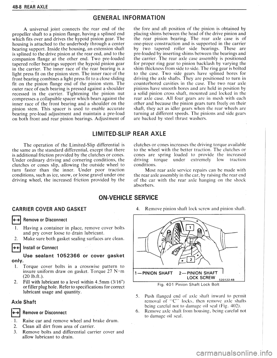
4. Remove pinion shaft lock screw and pinion shaft.
1 -PINION SHAFT 2-PINION SHAFT 1
SCREW 520122 48
Fig. 401 Pinion Shaft Lock Bolt
5. Push flanged end of axlc shalt inward to pcrmil
removal of "C" locks, thcn rcmovc axlc shafts
being
careful not to cl;uii~~gc oil scal (Fig. 402).
6. Remove axlc shaft from housing, bcing curcl'ul not
to
damage oil scal.
Page 284 of 1825
REAR AXLE 48-1 1
Rear Wheel Bolt
Remove or Disconnect 1.
1. Raise vehicle on hoist allowing axle to hang
freely. 2.
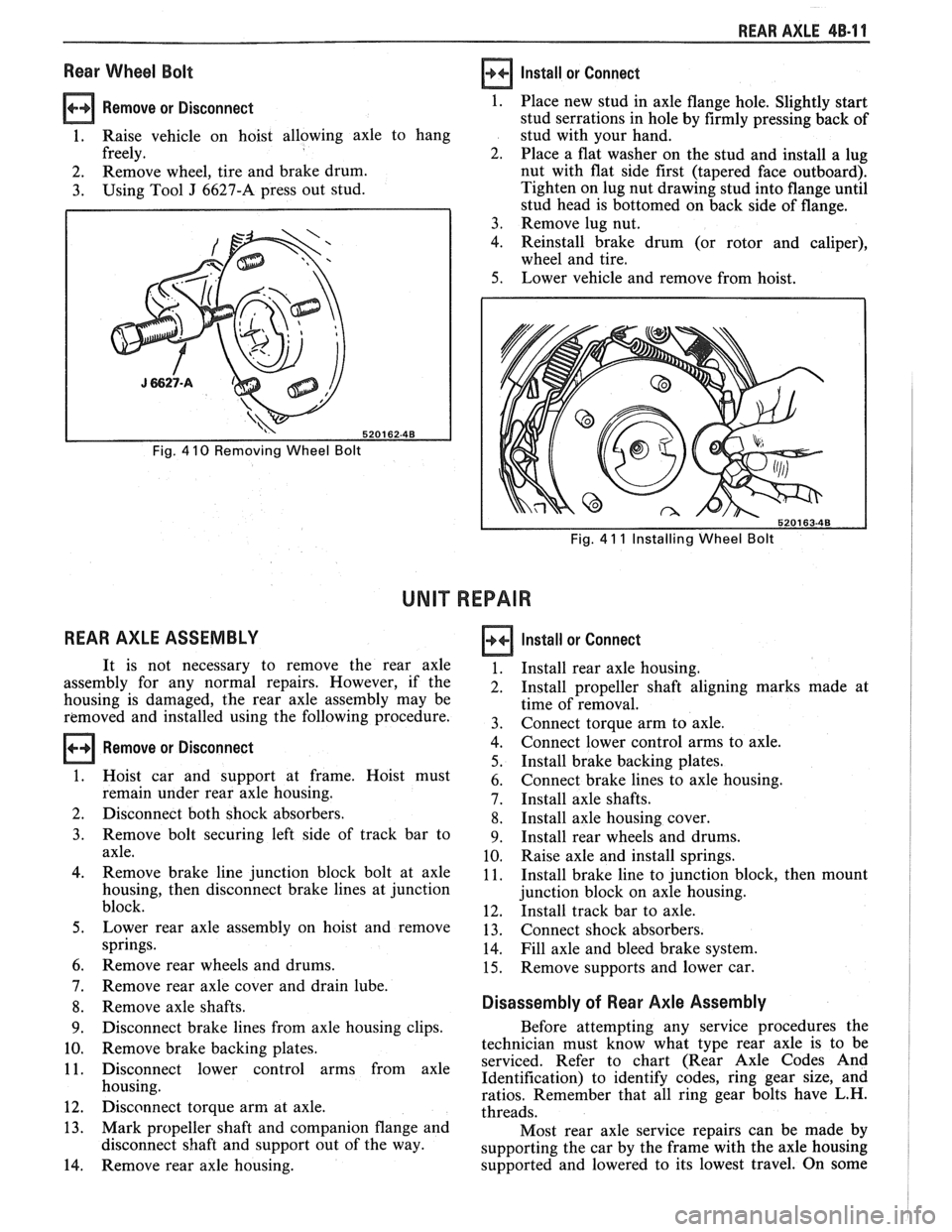
2. Remove
wheel, tire and brake drum.
3. Using Tool J 6627-A press out stud.
Fig. 4 10 Removing Wheel Bolt
REAR AXLE ASSEMBLY
Install or Connect
Fig. 4 11 Installing Wheel Bolt
UNIT REPAIR
Remove or Disconnect
Place new stud in axle flange hole. Slightly start
stud serrations in hole by firmly pressing back of
stud with your hand.
Place a flat washer on the stud and install a lug
nut with flat side first (tapered face outboard).
Tighten on lug nut drawing stud into flange until
stud head is bottomed on back side of flange.
Remove lug nut.
Reinstall brake drum (or rotor and caliper),
wheel and tire.
Lower vehicle and remove from hoist.
It is not necessary to remove the rear axle
assembly for any normal repairs. However, if the
housing is damaged, the rear axle assembly may be
removed and installed using the following procedure.
Hoist car and support at frame. Hoist must
remain under rear axle housing.
Disconnect both shock absorbers.
Remove bolt securing left side of track bar to
axle.
Remove brake line junction block bolt at axle
housing, then disconnect brake lines at junction
block.
Lower rear axle assembly on hoist and remove
springs.
Remove rear wheels and drums.
Remove rear axle cover and drain lube.
Remove axle shafts.
Disconnect brake lines from axle housing clips.
Remove brake backing plates.
Disconnect lower control arms from axle
housing.
Disconnect torque arm at axle.
Mark propeller shaft and companion flange and
disconnect shaft and support out of the way.
Remove rear axle housing.
Install or Connect
Install rear axle housing.
Install propeller shaft aligning marks made at
time of removal.
Connect torque arm to axle.
Connect lower control arms to axle.
Install brake backing plates.
Connect brake lines to axle housing.
Install axle shafts.
Install axle housing cover.
Install rear wheels and drums.
Raise axle and install springs.
Install brake line to junction block, then mount
junction block on axle housing.
Install track bar to axle.
Connect shock absorbers.
Fill axle and bleed brake system.
Remove supports and lower car.
Disassembly of Rear Axle Assembly
Before attempting any service procedures the
technician must know what type rear axle is to be
serviced. Refer to chart (Rear Axle Codes And
Identification) to identify codes, ring gear size, and
ratios. Remember that all ring gear bolts have L.H.
threads.
Most rear axle service repairs can be made by
supporting the car by the frame with the axle housing
supported and lowered to its lowest travel. On some
Page 290 of 1825
REAR AXLE 48-1 7
approached. No further tightening should be
attempted until the pre-load has been checked.
7. Check pre-load by using an inch pound torque
wrench.
NOTICE: After pre-load has been checked, final
tightening should be done very carefully. For
example, if when checking, pre-load was found to
be 0.6
N-m (5 lbs. in.), any additional tightening
of the pinion nut can add many additional pound
inch of torque. Therefore, the pinion nut should be
further tightened only a little at a time and the
pre-load should be checked after each slight
amount of tightening. Exceeding pre-load
specifications will compress the collapsible spacer
too far and require the installation of a new
collapsible spacer.
While observing the preceeding note, carefully set
pre-load at 2.7 to 3.6
N-m (24 to 32 1b.in.) on new
bearings or 1.0 to 1.4
N m (8 to 12 1b.in.) on used
bearings.
8. Rotate pinion several times to assure that
bearings have been seated. Check pre-load again.
If pre-load has been reduced by rotating pinion,
reset pre-load to specifications.
Rear Axle Backlash Adjustment
1. Install rear axle case into carrier, using shims as
determined by the side bearing pre-load
adjustment.
2. Rotate rear axle case several times to seat
bearings, then mount dial indicator. Use a small
button on the indicator stem so that contact can
be made near heel end of tooth. Set dial indicator
so that stem is in line as nearly as possible with
gear rotation perpendicular to tooth angle for
accurate backlash reading.
3. Check backlash at three or four points around
ring gear. Lash must not vary over
.05mm (.002")
around ring gear. Pinion must be held stationary
when checking backlash. If variation is over
.05mm (.002") check for burrs, uneven bolting
conditions or distorted case flange and make
corrections as necessary.
4. Backlash at the point of minimum lash should be
between .13 and
.23mm (.005" and ,009") for all
new gears.
5. If backlash is not within specifications, correct by
increasing thickness of one shim and decreasing
thickness of other shim the same amount. This
will maintain correct rear axle side bearing
pre-load.
For each
.03mm (.001") change in backlash
desired, transfer
.05mm (.002") in shim
thickness. To decrease backlash
.03mm (.00lU),
decrease thickness of right shim .05mm (.002")
and increase thickness of left shim .05mm (.
002 "). To increase backlash .05mm (.002 ")
increase thickness of right shim .10mm (.004")
and decrease thickness of left shim .10mm (.
004"). 6.
When backlash is correctly adjusted, remove both
bearing caps and both shim packs.
Keep packs in their respective position, right or
left side.
Select a shim
.10mm (.004") thicker than the one
removed from the left side, then insert left side
shim pack between the spacer and the left bearing
race. Loosely install bearing cap.
7. Select a shim
.10mm (.004") thicker than the one
removed from right side and insert between the
spacer and the right bearing race. It will be
necessary to drive the right shim into position
(Fig. 614).
8. Torque to 75 Nem (55 1b.ft.).
9. Recheck backlash
and correct if necessary.
10. Install axles (See Rear Axle Installation).
11.
Use sealant 1052366 or cover gasket
only.
Install cover and torque cover bolts to 27
N-m (20 1b.ft.).
12. Fill rear axle to proper level with the specified
lubricant. Refer to specifications.
LIMITED SLIP REAR AXLE (GONE TYPE)
The cone-type limited-slip differential has several
definite operating characteristics. An understanding of
these characteristics is necessary as an aid to diagnosis.
The clutch energizing force comes from the
thrust side of the gears. Consequently, a free spinning
wheel may not have enough resistance to drive torque
to apply the clutch cones. If this occurs, apply the
parking brake a few notches which will provide enough
resistance to energize the clutch cones.
Energizing the clutch cones is independent of
acceleration; therefore, a very slow application of the
throttle on starting is recommended to provide
maximum traction by preventing "break away" of
either rear wheel.
Improper operation is generally indicated by cone
slippage or grabbing. Sometimes this produces a
chatter or whirring sound. However, these sounds do
not always indicate failure as they could be produced
from a lack of proper lubrication. For example, under
certain conditions where one wheel is on
a very slippery
surface and the other on dry pavement, wheel spin can
occur if over acceleration is attempted. Continued
spinning may cause audible noise, such as a whirring
sound, due to the cones lacking sufficient lubricant.
This does not necessarily indicate failure of the unit.
During regular operation (straight ahead driving)
when both wheels rotate at equal speeds, there is an
approximately equal driving force delivered to each
wheel. When cornering, the inside wheel delivers extra
driving force causing slippage in both clutch cones.
Consequently, the operational life of the limited slip
unit is dependent upon equal rotation of both wheels
during straight ahead operation. If wheel rotation for
both rear wheels is not equal during straight ahead
operation, the limited-slip unit will constantly be
functioning as if the vehicle were cornering. This will
impose constant slippage on the clutch cones and will
eventually lead to abnormal wear on the clutch cones.
Therefore, it is important that there be no excessive
differences in the rear wheel tire sizes, air pressures, or
Page 295 of 1825
5-2 BRAKES
GENERAL DESCRIPTION
COMPOSIE EASTER CYLINDER
This vehicle uses a composite master cylinder which has
an aluminum body and a clear nylon reservoir with fluid
level indicators. The master cylinder uses a "quick take-up" feature in the
rear chamber to reduce pedal travel which may result from
increased fluid displacement required to move the caliper
piston. The quick take-up master cylinder includes a spring
loaded ball check valve which holds pressure in the
large-
diameter rear chamber. When the brake is first applied, the
movement of the rear piston causes fluid to be displaced
forward, past the primary piston primary seal and into the
primary high pressure chamber, which feeds the front
brakes. At a predetermined pressure, 480-690
kPa (70-100
mi), the ball unseats and fluid from the largi! rear bore is
disblaced past the ball and into the reservoir. The primary
and secondary high pressure chambers supply pressure to
the front and rear brakes, respectively, in the usual way.
When the pedal is released, the large-bore chamber is filled
with fluid by drawing fluid from the reservoir around the
quick take-up lip seal, and also through a small orifice in the
ball seat.
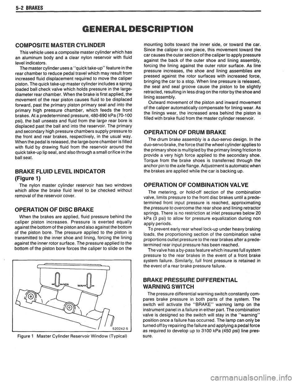
BRAKE FLUID LEVEL INDICATOR
(Figure 1)
The nylon master cylinder reservoir has two windows
which allow the brake fluid level to be checked without
removal of the reservoir cover.
OPERATION OF DISC BRAKE
When the brakes are applied, fluid pressure behind the
caliper piston increases. Pressure is exerted equally
against the bottom of the piston and also against the bottom
of the piston bore. The pressure applied to the piston is
transmitted to the inner shoe and lining, forcing the lining
against the inner rotor surface. The pressure applied to the
bottom of the piston bore forces the caliper to slide on the
Figure
1 Master Cylinder Reservoir Window (Typical) mounting bolts toward the inner side,
or toward the car.
Since the caliper is one piece, this movement toward the
car causes the outer section of the caliper to apply pressure
against the back of the outer shoe and lining assembly,
forcing the lining against the outer rotor surface. As line
pressure increases, the shoe and lining assemblies are
pressed against the rotor surfaces with increased force,
bringing the car to a stop. When line pressure is released,
the seal and seal groove cause the piston to be slightly
retracted, resulting in less drag on the rotor by the shoe and
lining assembly.
Outward movement of the piston and inward movement
of the caliper automatically compensate for lining wear. As
the linings wear, the increased area behind the piston is
filled with brake fluid from the master cylinder reservoir.
OPERATION OF DRUM BRAKE
The drum brake assembly is a duo-servo design. In the
duo-servo brake, the force that the wheel cylinder applies to
the primary shoe is
multipled by the primary lining friction to
provide a very high force applied to the secondary shoe.
Torque from the brake shoes is transferred through the anchor pin to the axle flange. Adjustment is automatic when
the brakes are applied while the car is backing up.
OPERATION OF COMBINATION VALVE
The metering, or hold-off section of the combination
valve, limits pressure to the front disc brakes until a prede-
termined front input pressure is reached, approximating
the pressure to overcome the rear shoe and lining retractor
springs. There is no restriction at inlet pressures below 20
kPa (3 psi) to allow for pressure equalization during non
apply periods.
To prevent early rear wheel lock-up under heavy braking
loads, the proportioning section of the combination valve
proportions outlet pressure to the rear brakes after a prede-
termined rear input pressure has been reached.
The valve has a by-pass feature which insures full system
pressure to the rear brakes in the event of a front brake
system failure. Similarly, full front pressure is retained in
the event of a rear brake pressure failure.
BRAKE PRESSURE DIFFERENTIAL
WARNING
SWITCH
The pressure differential warning switch constantly com-
pares brake pressure in both parts of the system. The
switch will activate the "BRAKE" warning lamp on the
instrument panel in a failure in either part. The combination
valve is designed so the switch will stay in the "warning"
position once a failure has occurred. The lamp can only be
turned off by repairing the failure and applying a pedal force
as required to develop up to 3100
kPa (450 psi) line pres-
sure.