ABS PONTIAC FIERO 1988 Service Repair Manual
[x] Cancel search | Manufacturer: PONTIAC, Model Year: 1988, Model line: FIERO, Model: PONTIAC FIERO 1988Pages: 1825, PDF Size: 99.44 MB
Page 16 of 1825
- -
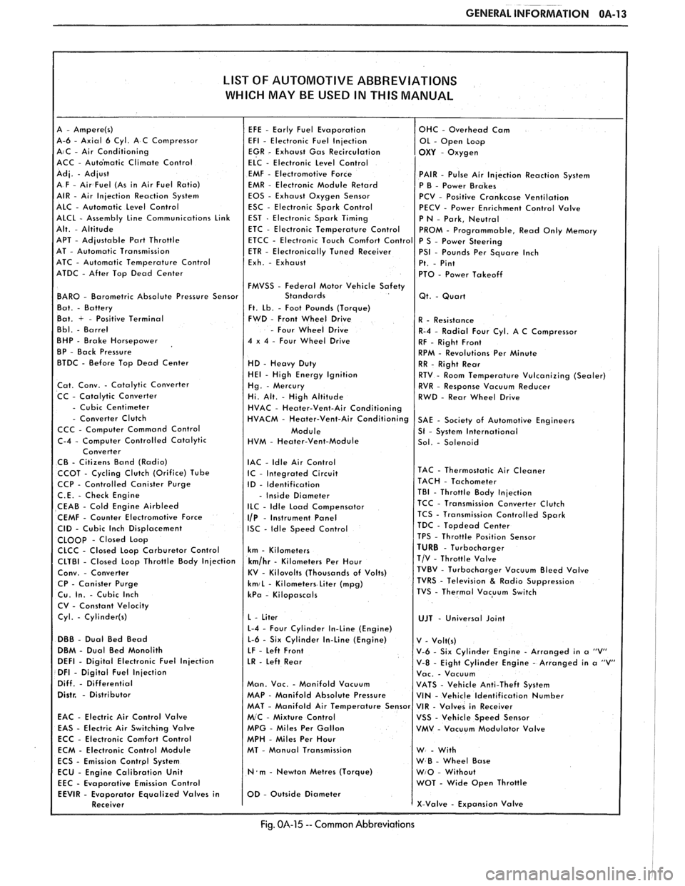
GENERAL INFORMATION OA-13
LIST OF AUTOMOTIVE ABBREVIATIONS
WHICH MAY
BE USED IN THIS MANUAL
A-6 - Axial 6 Cyl. A C Compressor AIC - Air Conditioning
ACC - Auto'matic Climate Control
EMF
- Electromotive Force PAIR - Pulse Air Injection Reaction System
EMR - Electronic Module Retard
P B - Power Brakes
EOS - Exhaust Oxygen Sensor
PCV - Positive Crankcase Ventilation
ESC - Electronic Spark Control
PECV - Power Enrichment Control Valve
APT
- Adjustable Part Throttle
AT - Automatic Transmission
ATC - Automatic Temperature Control
ATDC
- After Top Dead Center
FMVSS
- Federal Motor Vehicle Safety BAR0 - Barometric Absolute Pressure Sensor
Ft. Lb. - Foot Pounds (Torque)
Bat. + - Positive Terminal FWD - Front Wheel Drive
- Four Wheel Drive
BHP - Brake Horsepower 4 x 4 - Four Wheel Drive
BP - Back Pressure
BTDC - Before Top Dead Center
HD - Heavy Duty HE1 - High Energy Ignition
Cat. Conv. - Catalytic Converter
CC - Catalytic Converter
- Cubic Centimeter - Converter Clutch
CCC - Computer Command Control
HVM
- Heater-Vent-Module
IAC
- ldle Air Control CCOT - Cycling Clutch (Orifice) Tube IC - Integrated Circuit CCP - Controlled Canister Purge
ID - Identification
C.E. - Check Engine - Inside Diameter
CEAB - Cold Engine Airbleed ILC - Idle Load Compensator
CEMF - Counter Electromotive Force I/P - Instrument Panel
CID - Cubic Inch Displacement ISC - Idle Speed Control CLOOp - Closed Loop
CLCC - Closed Loop Carburetor Control km - Kilometers
CP
- Canister Purge kmiL - Kilometers Liter (mpg) Cu. In. - Cubic Inch kPa - Kilopascals
CV - Constant Velocity
Cyl.
- Cylinder(s)
L-4 - Four Cylinder In-Line (Engine)
DBB - Dual Bed Bead L-6 - Six Cylinder In-Line (Engine)
DBM - Dual Bed Monolith
LF - Left Front DEFl - Digital Electronic Fuel Injection LR - Left Rear DFI - Digital Fuel Injection
Diff. - Differential Man. Vac. - Manifold Vacuum Distr. - Distributor MAP - Manifold Absolute Pressure
EAC
- Electric Air Control Valve
EAS - Electric Air Switching Valve MPG - Miles Per Gallon
ECC - Electronic Comfort Control
MPH - Miles Per Hour
ECM - Electronic Control Module MT - Manual Transmission
N.m - Newton Metres (Torque)
Emission Control
Fig. 014-15 -- Common Abbreviations
Page 85 of 1825
1 D1-6 R-4 AIR CONDITIONING COMPRESSOR OVERHAUL
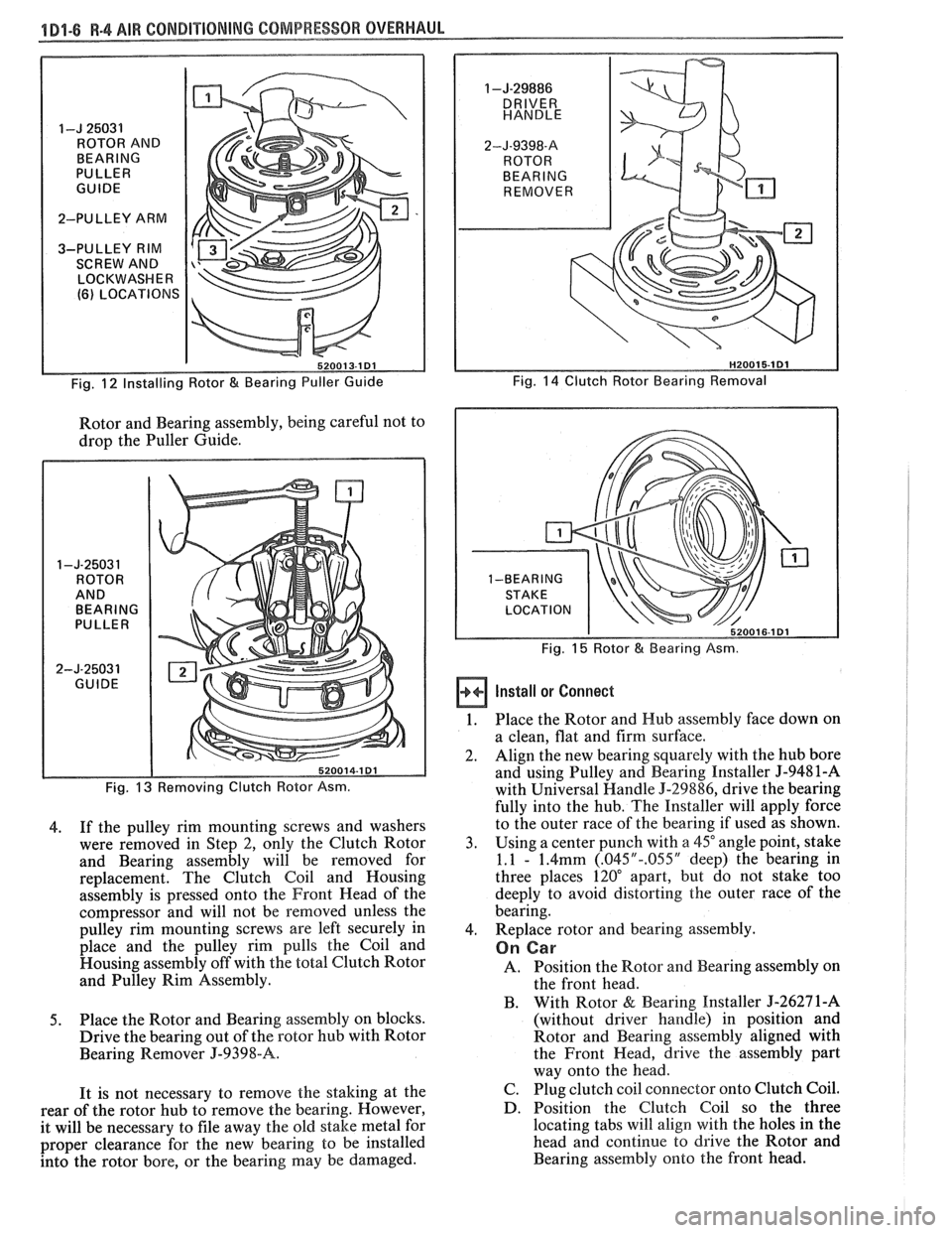
I-J 25031
ROTOR AND
BEARING
PULLER
GUIDE
2-PULLEY ARM
3-PULLEY RIM SCREW AND
LOCKWASHER
(6) LOCATIONS
Fig.
12 Installing Rotor & Bearing Puller Guide
Rotor and Bearing assembly, being careful not to
drop the Puller Guide.
1 -J-2503 1 ROTOR
AND BEARING
PULLER
2-J-25031 GUIDE
Fig.
13 Removing Clutch Rotor Asm.
4. If
the pulley rim mounting screws and washers
were removed in Step 2, only the Clutch Rotor
and Bearing assembly will be removed for
replacement. The Clutch Coil and Housing
assembly is pressed onto the Front Head of the
compressor and will not be removed unless the
pulley rim mounting screws are left securely in
place and the pulley rim pulls the Coil and
Housing assembly off with the total Clutch Rotor
and Pulley Rim Assembly.
5. Place the Rotor and Bearing assembly on blocks.
Drive the bearing out of the rotor hub with Rotor
Bearing Remover
J-9398-A.
It is not necessary to remove the staking at the
rear of the rotor hub to remove the bearing. However,
it will be necessary to file away the old stake metal for
proper clearance for the new bearing to be installed
into the rotor bore, or the bearing may be damaged.
1 -J-29886
2-J-9398-8
REMOVER
Fig.
14 Clutch Rotor Bearing Removal
Fig.
15 Rotor & Bearing Asm.
Install or Connect
1. Place the Rotor and Hub assembly face down on
a clean, flat and firm surface.
2. Align
the new bearing squarely with the hub bore
and using Pulley and Bearing Installer
5-9481-A
with Universal Handle 5-29886, drive the bearing
fully into the hub. The Installer will apply force
to the outer race of the bearing if used as shown.
3. Using
a center punch with
a 45" angle point, stake
1.1
- 1.4mm (.045"-.055" deep) the bearing in
three places 120" apart, but do not stake too
deeply to avoid distorting the outer race of the
bearing.
4. Replace
rotor and bearing assembly.
On Car
A. Position the Rotor and Bearing assembly on
the front head.
B. With Rotor
& Bearing Installer J-26271-A
(without driver handle) in position and
Rotor and Bearing assembly aligned with
the Front Head, drive the assembly part
way onto the head.
C. Plug clutch coil connector onto Clutch Coil.
D. Position the Clutch Coil so the three
locating tabs will
align with the holes in the
head and continue to drive the Rotor and
Bearing assembly onto the front head.
Page 102 of 1825
BUMPERS 28-1
SECTION 2B
BUMPERS
NOTICE: These fasteners are important attaching parts in that they could affect the performance of vital parts and
systems,
andlor could result in major repair expense. They must be replaced with one of the same part number or with an
equivalent
part if replacement becomes necessary. Do not use a replacement part of lesser quality or substitute design.
Torque values must be used as specified during reassembly to assure proper retention of all parts. There is to be no
welding as it may result in extensive damage and weakening of the metal.
NOTICE: The anti-theft label on some major sheet metal, engines, and transmissions must be masked prior to
painting, rustproofing, undercoating, etc. The mask MUST be removed following the above operations. Failure to keep
the label clean and readable may result in liability for violation of Federal Vehicle Theft Prevention Standard, and subject
the vehicle owner to possible suspicion that the part was stolen.
CONTENTS
General Description ................................ 2B-1 On-Vehicle Service ..................................... 2B-4
........................................... ..................... Service Procedures .. ........... 2B- 1 Specifications 2B-5
GENERAL DESCRIPWIBN
The bumpers on all Pontiac automobiles are remover.
Install new tape (double-coated neoprene
designed so that the vehicle can withstand a collision foam type)
to the back side of the rub strip.
into a fixed barrier at
5 mph. After absorbing the
energy of a collision, the bumpers restore themselves After
rub strip is installed, roll along entire
to their original position. surface with a roller
in order to insure a good bond.
The front and rear bumper fascias are made of
urethane. Urethane will withstand minor impact and
return to its original shape. Some front bumper fascias
are integral with the front end panel.
Some models use both steel and aluminum
bumper reinforcements. Usage is based on
EPA weight
class requirements.
BUMPER FASCIA RUB STRIPS
Some front and rear fascia rub strips are made of
a shiny plastic material. If a rub strip of this type loses
its lustre, the original shine can be restored by using
GM Plastic Cleaner or its equivalent. Follow directions
on the label.
SERVICE PROCEDURES
RUB STRIPS
Remove and Replace
Some plastic rub strips have an adhesive tape
backing (similar to a body side molding) and some have
studs or retaining tabs. In order to properly remove the
adhesive tape and avoid paint damage to the fascia, use
either a release agent or a heat lamp to soften the bond
of the adhesive tape to the fascia. In some cases, it will
be necessary to replace the rub strip with a new rub
strip instead of reusing the old one.
If the old rub strip is salvagable, remove all tape
from the back side of the rub strip as previously
described. Wipe strip clean with a wax and adhesive
FRONT BUMPER FASCIA (FRONT END PANEL)
Removal
Place a jack stand under fascia assembly before
removing bolts to prevent it from dropping down when
fascia attaching bolts are removed. Fascia will pivot on
the opposite end when one end is disconnected. Do not
rotate energy absorber any more than necessary to
align mounting holes.
1. Remove fascia attaching bolts and fascia to
fender attaching screws on right and left side, and
remove fascia and spacers.
2. If energy absorber is to be replaced, remove the
bolts and nuts from the front of the unit and the
nut from the stud at the rear.
Installation
1. Install energy absorber if removed.
2. Support fascia during installation to prevent
rotation of energy absorbers.
3. Install spacers and bolts at fascia to energy
absorber brackets.
4. Install fascia to fender attaching screws.
5. Check for proper clearance.
6. If adjustment is required to align fascia, loosen
energy absorber mounting bolts and position as
required (holes are slotted). Adjustment side to
side can be made by loosening fascia bracket
bolts. Torque all bolts and nuts. (See
Specifications.)
Page 103 of 1825
2B-2 BUMPERS
REAR BUMPER FASCIA
Removal
Place a jack stand under fascia before removing
bolts to prevent it from dropping down when fascia
attaching bolts are removed. Fascia will pivot on the
opposite end when one end is disconnected. Do not
rotate energy absorber any more than necessary to
align mounting holes.
1. Remove fascia attaching bolts and fascia to
fender attaching screws on right and left side, and
remove fascia and spacers.
2. If energy absorber is to be replaced, remove the
bolts and nuts from the front of the unit and the
nut from the stud at the rear. The stud at the rear
of the absorber is attached to a bracket in the
frame. Remove the bolt holding this bracket in
the frame to remove the absorber.
Installation
1. Install energy absorber if removed.
2. Support fascia during installation to prevent
rotation of energy absorbers.
3. Install spacers and bolts at fascia to energy
absorber brackets.
4. Install fascia to fender attaching screws.
5. Check for proper clearance.
6. If adjustment is required to align the fascia, use
shims as necessary. Vertical and lateral
adjustment can be made at slots in fascia and
absorber brackets. Torque all bolts and nuts. (See
Specifications.)
FRONT BUMPER
Removal
1. Remove
front end fascia as shown in Section 2C.
2. Remove bumper barlenergy absorber assembly
from body.
3. If energy absorber must be replaced, drill out pop
rivets, and install new absorber with nuts, bolts,
and locking washers.
4. To install, reverse above procedure.
REAR BUMPER
Removal
1. Remove left hand rear quarter trim panel.
2. Remove right hand rear quataer trim panel.
3. Remove spare tire assembly.
4. Remove rear center trim panel.
5. Remove right tail light assembly.
6. Remove left tail light assembly.
7. Remove tail light center piece.
8. Remove bumper cover lower retainers.
9. Remove right-side bumper cover fasteners from
inside of compartment.
10. Remove left side bumper cover fasteners from
inside of compartment.
11. Remove bumper cover upper retainers.
12. Remove cover.
13. To dissasemble impact bar, proceed as follows:
a. Remove bolts attataching impact bar to
rear end panel.
b. Remove rivets retaining pad to impact
bar.
14. To install, reverse above procedure.
BUMPER ENERGY ABSORBING UNITS
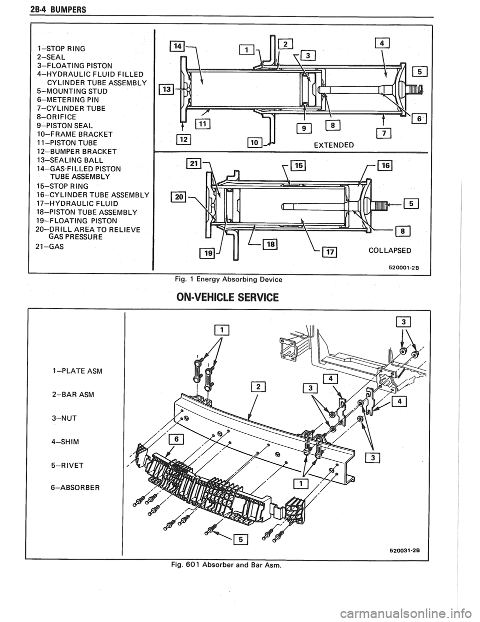
The absorbing capability for both front and rear
bumper systems is achieved through two energy
absorbing devices in each bumper. These units convert
the energy of an impact into heat and restoration. The
energy absorbing device consists of two main
subassemblies: the piston tube assembly and the
cylinder tube assembly. The piston tube assembly is
filled with an inert gas under pressure and consists of
a bumper bracket, piston tube, orifice, seal, piston seal,
piston, and stop-ring. The cylinder tube assembly is
filled with a hydraulic fluid and consists of a frame
bracket, cylinder tube, mounting stud, and metering
pin.
Upon impact, as the energy absorber is collapsed,
the hydraulic fluid in the cylinder tube is forced into
the piston tube through the orifice. The metering pin
controls the rate at which this fluid passes from the
cylinder tube through the orifice and into the piston
tube. This controlled passage of fluid provides the
energy absorbing action.
The hydraulic fluid that is forced from the
cylinder tube into the piston tube displaces the floating
piston, compressing the gas behind the floating piston.
After impact, the pressure of the compressed gas
behind the floating piston forces the hydraulic fluid
back into the cylinder tube assembly, extending the
unit to its normal position.
Some front and rear bumpers (J and
F Models)
use a plastic honeycomb pad energy absorber (except
J wagon rear bumper). This energy absorber will
compress on impact, and both the energy absorber and
the urethane fascia will return to their original shape.
The energy absorber pad has no moving parts.
The J wagon rear bumper system uses a hydraulic
energy absorbing unit, more commonly known as a
"minisorber".
TESTING FRONT OR REAR ENERGY
ABSORBER OPERATION
The right and left energy absorbing devices are to
be diagnosed separately. The following checks are to be
made on each unit:
1. Leakage
Some oil wetting may be visible due to the grease
packed in the crimp recess. Therefore, a stain or trace
of oil on the piston tube near the crimp is normal.
However, if oil is dripping continuously from the crimp
or the stud end of the unit, a leak is indicated and the
unit should be replaced.
Page 104 of 1825
BUMPERS 28-3
Check the bumper bracket, piston tube, frame
bracket and cylinder tube for evidence of visible
distortion. Scuffing of the piston tube will occur when
the unit is stroked, and this is considered normal.
If there is obvious damage to the unit, it should
be replaced.
3. On-Bench Test
a. Position energy absorber lengthwise in arbor
press.
b. Using
a suitable measuring device, note original
position of unit, then use press to compress unit
at least
3/8".
c. Release pressure and determine whether unit has
returned to original position.
If not, discard unit.
4. Inspection After Collision
If the collision was so severe that the bumper did
not return to its original position, the energy
absorber(s) will require replacing.
a. Stand clear
of the bumper.
b. Provide
a positive restraint, such as a chain or
cable to hold the bumper in position.
c.
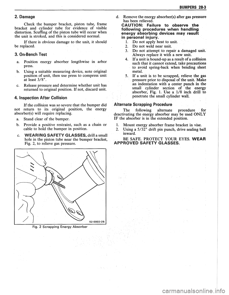
WEARING SAFETY GLASSES, drill a small
hole in the piston tube near the bumper bracket,
Fig.
2, to relieve gas pressure.
Fig. 2 Scrapping Energy Absorber
d. Remove the energy absorber(§) after gas pressure
has been relieved.
CAUTION: Failure to observe the
following procedures when handling
energy absorbing devices
nnay result
in personal injury.
1. Do not apply heat to unit.
2. Do not weld near unit.
3. Do not attempt to repair a damaged unit.
Always replace it with a new unit.
4. If a unit is bound-up as a result of a collision
such that it cannot extend, take precautions
to avoid spring-back when bending sheet
metal.
5. If
a unit is to be scrapped, relieve the gas
pressure prior to disposal of the unit. Make
an indentation with a center punch in the
small cylinder section of the energy
absorber, Fig.
1. Use a 1/8 inch drill to
penetrate the small cylinder wall.
Alternate Scrapping Procedure
The following alternate procedure for
deactivating the energy absorber may be used
ONLY
IF the absorber is in the extended position.
1. Mount energy absorber frame bracket in vise.
2. Using a 5/32" drift pin punch, drive sealing ball
inward.
BE SAFE. PROTECT YOUR EYES.
WEAR
APPROVED SAFETY GLASSES.
Page 105 of 1825
28-4 BUMPERS
1-STOP RlNG
2-SEAL 3-FLOATING PISTON
4-HYDRAULIC FLUID FILLED
CYLINDER TUBE ASSEMBLY
5-MOUNTING STUD
6-METERING PIN
7-CYLINDER TUBE
8-ORIFICE
9-PISTON SEAL
10-FRAME BRACKET
11-PISTON TUBE
12-BUMPER BRACKET
13-SEALING BALL
14-GAS-FILLED PISTON
TUBE ASSEMBLY
15-STOP RlNG
16-CYLINDER TUBE ASSEMBLY
17-HYDRAULIC FLUID
18-PISTON TUBE ASSEMBLY
19-FLOATING PISTON
20-DRILL AREA TO RELIEVE
GAS PRESSURE
21 -GAS m
COLLAPSED
Fig. 1 Energy Absorbing Device
ON-VEHICLE SERVICE
1 -PLATE ASM
2-BAR ASM
3-NUT
4-SH
I M
5-RIVET
6-ABSORBER
Fig.
60 1 Absorber and Bar Asm.
Page 108 of 1825
CHASSIS SHEET METAL 2C-1
SECTION %C
CHASS S SHEET METAL
NOTICE: These fasteners are important attaching parts in that they could affect the performance of vital
parts and systems,
andlor could result in major repair expense. They must be replaced with one of the same part
number or with an equivalent part if replacement becomes necessary. Do not use a replacement part of lesser
quality or substitute design. Torque values must be used as specified during reassembly to assure proper retention
of all parts. There is to be no welding as it may result in extensive damage and weakening of the metal.
For prevailing torque
nut(s) and bolt(s), refer to the "Reuse of Prevailing Torque Nut(s) and Bolt(s)" chart in
Section OA.
CONTENTS
............................... General Description 2C-1
.............................................. Fasteners 2C- I
.......................... Anti-Corrosion Materials 2C- 1
................................ Service Procedures 2C-1
..................................... Hood Assembly 2C-1
.......................................... Hood Hinge 2C-2
........................................... Hood Latch 2C-2
......................................... Fender Panel 2C-3
.............................. Molding Replacement 2C-3
Aluminum Panel Repair Procedures
............. 2C-3
PaintingIRepairing Non-Metal Parts ............. 2C-3
RepairingIRefinishing Urethane
Bumpers and Front End Panels
................. 2C-4
.............................. Paint Color Matching 2C-5
Proper Identification and Painting of
............................. Interior Plastic Trim.. 2C-6
....................................... Test Procedure 2C-6
Painting Interior Plastic Parts
..................... 2C-6
...................... Polypropylene Plastic Parts .2C-6
Rigid or Hard Plastic Parts ....................... 2C-7
Vinyl and Flexible ABS Parts
.................... 2C-7
On-Vehicle Sewice ................................ 2C-7
GENERAL DESCRIPTION
FASTENERS SERVICE PROCEDURES
Many aluminum components are used in the
current models. Aluminum in contact with steel may
corrode rapidly if not protected by means of special
finishes or isolators.
Many of the fasteners used in the front sheet
metal area have the new GM
6174M finish which will
provide adequate protection. In some places, how-
ever, special fasteners are used in conjunction with
aluminum components. These special fasteners are
argent silver in order to more easily identify them
from the standard metric fasteners which are a
medium blue in color.
When replacing fasteners in the front sheet
metal area, it is advisable to avoid substitution of
otherwise similar fasteners in locations which should
use GM
6174M type fasteners or special fasteners for
aluminum components.
NOTICE: Failure to follow this precaution may
result in premature corrosion of the sheet metal in
the areas mentioned above.
ANTI-CORROSION MATERIALS
Anti-corrosion materials have been applied to
the interior surfaces of some metal panels to provide
rust resistance. When servicing these panels, areas on
which these materials have been disturbed should be
properly
recoated with service-type anti-corrosion
material.
HOOD ASSEMBLY
The hood is composed of a single outer panel
and an inner panel reinforcement. The hood may be
either steel or aluminum.
Adjust
Figure 1
Slotted holes are provided at all hood hinge
attaching points for proper adjustment
- both verti-
cally and fore and aft. Vertical adjustment at the front
may be made by adjusting rubber bumpers up and
down. For best appearance, make one adjustment at a
time.
TO RAISE OR LOWER THE REAR comers of
the hood for proper alignment to the fenders, and to
insure contact with the hood side wedges, proceed as
follows:
1. Loosen hinge-to-hood attaching screws.
2. Reposition hood assembly.
3. Tighten hinge-to-hood attaching screws to
specifications.
4. If necessary, repeat procedure on opposite side
of hood.
Page 110 of 1825

CHASSIS SHEET METAL 2C-3
3. Allow hood to open, and tighten latch bolts in
new location.
FENDER PANEL
An outer fender panel with a plastic inner panel
is used. Care should be used in handling raw fenders
due to the lack of fender rigidity prior to installation.
Body surfaces at molding areas must be cleaned
thoroughly with suitable organic solvent immediately
prior to installation to ensure adhesion. Do not allow
adhesive surface of molding to come in contact with
wet solvent, dirt, or foreign matter.
NO"FICE: If heat source is used to condition
moldings prior to installation, the source is to
provide
uniform heating, not to exceed 85°F.
Application is to be made in a clean area with
ambient and body surface temperatures of at least
65°F.
The moldings are to be secured with two appli-
cations of a force of 20 pounds for the full length of
each section using a roller or other suitable tool.
Any section of molding removed once in contact
with the body surface must be replaced.
ALUMINUM PANEL REPAIR PROCEDURES
An aluminum hood (inner and outer panel) is
used on some vehicles. An aluminum panel can be
identified by checking it with a magnet, preferably in
the front corners to avoid any possible damage to the
paint. Aluminum will not attract a magnet.
Aluminum panels can be repaired successfully
with only slight changes of materials and techniques
commonly used to refinish steel panels. The necessary
modifications fall into two categories: 1) metal
preparation; and 2) painting.
Metal Preparation
1. Because aluminum is relatively easy to grind,
care must be taken not to use overly coarse abra-
sive discs or excessive grinder speeds (greater
than 2,000 rpm), both of which will cause
excessive heat and unnecessary metal removal.
2. Surface scratches should normally be removed
with 180 or 120 grit paper with scalloped edges.
Hand sanding with 80 grit paper will usually be
sufficient to remove excessive body filler or
heavy scratches, again followed with 180 grit
paper.
NOTICE: Avoid scratching aluminum when
sanding with 80 grit paper by hand.
3. Foam backed pads are recommended for
grinders used on aluminum, rather than the
stiffer rubber pads used for mounting abrasive
discs used on steel. The foam pad helps to
reduce heat build-up and improves blending for
feathering.
4. Localized heat, generated by grinding, can be
minimized by the use of a grease stick, such as
Formax F-160 or equivalent. This does, how-
ever, tend to load up the grinding discs quickly,
which should be periodically cleaned by rotating
them against a brush wetted with solvent.
5. If out-dings or minor convex defects need to be
filed, it is recommended to use a round edge,
double cut, flexible file with 22 teeth per inch
overlaid with 52 teeth per inch (such as
Nicholson
#50-412 or equivalent).
NOTICE: Keep file clean so that chips do not
scratch aluminum.
The use of heat is not recommended, since the
structural characteristics of aluminum are noticeably
affected by heat. A bent or buckled aluminum hood,
which exhibits strain cracks either before or after
straightening, should be replaced.
Both steel and aluminum panels can be metal
prepped and repaired with two-part polyester filler
materials in the same number of operations. The only
differences are that less aggressive type files and abra- sive discs should be used, with care being taken not to
overheat the aluminum.
Painting
Painting procedures for aluminum panels differ
very little from those used on steel panels. Two pre-
cautions should, however, be observed:
1. Alkaline base paint removers are not recom-
mended and should not be used.
2. Aluminum also requires a chemical cleaner such
as
DuPont 2253, Ditzler DX-533, or equivalent
be used on bare metal to remove contaminants
and corrosion. After cleaning, a conversion
coating such as DuPont
226S, Ditzler DX-503
or equivalent should be applied to promote
adhesion.
Beyond these considerations, painting alumi-
num panels should present no increases in difficulty or
changes in procedure and technique.
PAINTING AND REPAIRING NONMETAL
EXTERIOR PARTS 1
FiberglassIABS Plastic Panel Repair ~
A Plastic Solder Repair Kit can be used to repair
cracks, dents, or pits in fiberglass or ABS panels. A
Glass Woven Cloth should be installed on the under
side of a crack in the panel to structurally reinforce the
panel. The following procedure can be used to repair
the panels:
1. With a lacquer removing solvent, remove paint
from damaged area down to the fiberglass or
, ABS material. I
2. Scuff-sand area surrounding damaged area to
provide a good bonding surface.
Page 113 of 1825
866 CHASSIS SHEET METAL
PROPER IDENTIFICATION AND CDAlrUmNG
OF INTERIOR PWSTIC TRlM
Interior plastic trim parts are normally supplied
in only one color. It is necessary to paint most parts.
Most vinyl headlinings and soft vinyl seat cushion and
hack cover assemblies are furnished in colors.
Instructions on how to identify each paintable
plastic part, and how to apply the available paint
materials are as follows:
Paintable plastic trim components, as used on
General Motors interiors, can be divided into three
general types:
@ Polypropylene Plastic
@ ABS Plastic
@ Vinyl Plastic
Excluding the soft vinyl seat cushion and seat
back trim cover assemblies, the plastic used most
widely on the interior of bodies is "POLYPROPYL-
ENE" and, as noted later, requires special refinishing
materials and procedures. Therefore, it is important
for a painter to be able to identify each plastic in order
to paint it satisfactorily. The purpose of the following
tests is to determine the identity of a given plastic so
that the proper paint procedure and refinishing mate-
rials will be used.
TEST PROCEDURE
Polypropylene, ABS or Vinyl Plastic
From a hidden backside portion of the part,
remove a sliver of plastic with a sharp blade.
Holding the sliver with needle-nose pliers, put it
to a flame and observe whether or not any
smoke is given off when burning.
ABS PLASTIC will give off a HEAVY BLACK
SMOKE, and POLYPROPYLENE will burn
clean.
However, if a sliver gives off OTHER THAN
HEAVY BLACK SMOKE, it is either DIRTY
POLYPROPYLENE OR IS VINYL. To deter-
mine which it is, the following burn test should
be made with the hot tip of a clean copper wire.
Heat the tip of the copper wire to a "red-glow"
with a propane (gas) torch.
Touch the heated wire to a hidden portion of the
plastic in question, to get some of the plastic on
the wire.
Return the wire, with its
now plastic-coated tip,
to the flame and observe for flame color.
If the flame given off from the wire is of the
GREEN-TURQUOISE-BLUE RANGE, then
the PLASTIC IS VINYL. (Any other color
flame would indicate the material is dirty poly-
propylene.
)
PAINWING lNTERiOR PWSTIC PARTS
Before painting, always check the body number
plate of the car for the
correct trim code color number
for that model year. The body number plate is located
on the upper horizontal surface of the shroud. Interior
color is color keyed to this "Trim Combination Num-
ber" (TR) on the body plate. Each paint supplier pro-
vides an interior color chart which identifies their
stock number, color name, gloss factor and trim com-
bination number for each "conventional" interior
color. Charts listing "vinyl" interior colors are also
provided.
"CONVENTIONAL" interior acrylic colors are
designed for use only on hard trim parts, such as:
1. Steel parts (primer or sealer required on new
service parts).
2. Hard POLYPROPYLENE plastic ("Special
Primer" required
- See GM Parts Catalog).
3. Hard ABS plastic (NO primer necessary).
"VINYL" interior colors are designed for soft
and/or flexible trim parts, such as instrument panel
cover pad assemblies, upper door trim pad assem-
blies, molded headlining panels, head rests and assist
handles. These colors require a final top coat of clear
vinyl spray, with instrument panel pads requiring a
"nonglare" clear final top coat. Other trim parts
require a degree of gloss to match similar adjacent
parts.
POLYPROPYLENE PUSTIC PARTS
The system for painting polypropylene parts
involves the use of a special primer. It is essential that
the service part be first primed with a coating of spe-
cial POLYPROPYLENE PRIMER (Detroit
Autobody
#PP-2250, or equivalent) according to factory recom-
mendations on the can. Because the primer acts as a
bonding agent between the plastic and acrylic lacquer, failure to use it will result in color coat "lifting"
and/or
"peeling" problems. After priming, the part can be
color coated with conventional interior acrylic
lacquer,
PROCEDURE
1. Wash part thoroughly with a cleaning solvent ("Acryli-Clean," "Prep-Sol," or equivalent) that
will not leave any greasy film.
2. Apply a thin, wet coat of the special polypropyl-
ene primer according to label directions on can.
Wetness of primer is best determined by observ-
ing gloss reflection of spray application in ade-
quate lighting. Be sure primer application
includes all edges. Allow
the primer to flash dry
ONE (1) MINUTE MINIMUM and TEN (10)
MINUTES MAXIMUM. (If the flash period
before color coating should extend beyond ten
minutes, the primer MUST be reapplied to
avoid previously mentioned adhesion
problems
.)
Page 114 of 1825
CHASSIS SHEET METAL 2@-7
3. During the above flash time period (1 to 10 min-
utes), apply appropriate "conventional" interior acrylic lacquer color as required and allow
painted part to dry for
4 to 5 hours before install-
ing on car.
RlGlD OW HARD ABS PMS"TIC PARTS
Rigid or hard ABS plastic requires no primer.
"Conventional" interior acrylic lacquers adhere satis-
factorily to hard ABS plastics.
Procedure
1. Wash part thoroughly with a cleaning solvent
(Acrylic-Clean, Pre-Kleano, Prep-Sol or equiv-
alent) to remove any dirt or grease.
2. Apply appropriate "conventional" interior
acrylic lacquer color. Apply only sufficient
color for proper hiding to avoid washout of
"grain" effect.
3. Allow to dry and then install part.
VINYL AND FLEXIBLE (Son) ABS
PLASTIC PARTS
The outer cover or skin material of "flexible"
instrument panel cover (pad) assemblies is made of an
ABSIPVC plastic blend. The same is true of many
"padded" door trim assemblies. The soft cushion pad-
ding under the I.P. skin is urethane foam plastic. The
most widely used
"flexible" vinyls (poly vinyl chlo-
ride)
are coated fabrics, such as used in seat trim,
some door trim assemblies, molded headlining panels
and sun visors. Most head rests are "flexible" vinyls.
Examples of "hard vinyls are: door and front seat
back assist handles and coat hooks.
The paint system of vinyl and flexible ABS
plastic involves the use of interior "vinyl" color and a
clear vinyl top coat.
Procedure
1. Wash part thoroughly with a vinyl cleaning and
preparation solvent ("Vinyl Press"
- Ditzler,
"Vinyl Prep Conditioner"
- Detroit Autobody
or equivalent) to remove greasy film or silicone.
Wipe off cleaner while still wet with clean,
lint-
free cloth.
2. Immediately after wiping face dry, apply inte-
rior "vinyl" color in wet coats allowing suffi-
cient flash time between coats (see label
directions on can). Use proper "vinyl" color as
designated by interior trim combinations. Apply
only sufficient color for proper hiding to avoid
washout of "grain" effect. No primer or
primer-
sealer is required.
3. Before the final vinyl color coat has dried, apply
two coats of clear vinyl top coat spray (instru-
ment panels will require the "nonglare" clear top
coat). Do not allow the first spray coat to com-
pletely dry before spraying on the second. Use
top coat with appropriate gloss level to match adjacent similar components. This
clear coat is
necessary to control the gloss requirement and
prevent
'tracking" (rubbing-off) of the color
coat after drying.
4. Allow to dry according to label directions before
installing part.
ON-VEHICLE SERVICE
CONCEALED HEADLIGHTS
The concealed headlights used on this model are
electrically operated. When the headlights are turned
on, solid state circuitry activates the actuators. This
same circuitry senses when the actuators stop moving
and removes the ground to deactivate the actuators.
When the headlights are turned off, the actuators run
in opposite direction closing the headlight doors.
Should an electrical failure occur in the head-
light circuit, they may be raised manually by rotating
the knob on the actuator in a counterclockwise direc-
tion until the headlights are fully open. The headlights
may be lowered by rotating the knob on the actuator in
a clockwise direction until the headlights are fully
closed.
For electrical circuit information and diagnosis,
refer to Section
8A of this manual.
If it is desired to raise the headlights with the
lights off, either of the following procedures may be
used:
1. Turn the lights on. After the headlights are
open, disconnect the electrical connections at
the actuator connectors. Turn the lights off. The
headlights will now remain in the open position.
2. Turn the parking lights on. Depress the head-
light rocker switch lightly. The headlights may
then be raised "up" fully with the lights off.
Adjust
Because of the number of adjustments possible
and the number of attaching points of the concealed
headlight body assembly
(9), only those attachments
which control the adjustment desired should be loos-
ened. Make one
adjbstment at a time.
NOTICE: The headlight door does NOT have
slotted mounting holes and therefore is not
adjustable by itself. This insures proper clearance
between the headlight door and the hood and
fenders in both the raised and lowered positions.
The entire headlight body assembly must be
adjusted to achieve the desired appearance and
fit. Care should be exercised when adjusting the
headlight body assembly. Severe hammer blows could damage the die cast aluminum headlight
body assembly.
TO RAISE OR LOWER the headlight body
assembly, proceed as follows:
1. Open hood.
2. Raise headlights.