length PONTIAC FIERO 1988 Service Owner's Manual
[x] Cancel search | Manufacturer: PONTIAC, Model Year: 1988, Model line: FIERO, Model: PONTIAC FIERO 1988Pages: 1825, PDF Size: 99.44 MB
Page 435 of 1825
6C-4 ENGINE FUEL
to fully insert the unleaded gas nozzle will result in
gasoline splashing back out of the filler neck.
Fuel Gage Sending Unit
The fuel gage sending unit is attached to the top
of the fuel tank. It is held in place with a cam lock ring
and a gasket is used between the tank and sending unit.
Sending units have three hoses attached. One line
is for the fuel feed. The second line is connected to the
vapor canister, to keep fuel vapor from getting into the
air (see Section 6E). The third line is used as a fuel
return line to the tank.
On some sending units a wire is attached to the
unit. On others the connectors attach directly to the
sender.
When a fuel gage sending unit is removed always
make sure to install the gasket and any power or
ground leads that were removed.
DIAGNOSIS
Fuel system diagnostic procedures are located in
Section(s) 6E1 thru 6E3.
SERVICE PROCEDURES
If the fuel system is suspected of delivering an
improper amount of fuel, it should be inspected and
tested in the vehicle, as follows:
1. Make certain that there is fuel in the tank.
2. With the engine running, inspect for leaks at all
fuel feed pipe and hose connections from
fuel
tank to injection pump. Tighten any loose
connections. Inspect all hoses for flattening or
kinks which would restrict the flow of fuel. Air
leaks or restrictions on suction side of fuel pump
will seriously affect pump output.
FUEL SYSTEM PRESSURE RELIEF
CAUTION: To reduce risk of fire and
personal injury, it is necessary to
relieve duel system pressure before
servicing fuel system components. To
do this:
Remove "fuel pump" fuse from fuse
block in passenger compartment.
e Crank engine - engine will start and run
until fuel supply remaining in fuel lines is
consumed. Engage starter for
3.0
seconds to assure relief of any remaining
pressure.
e With ignition "OFF", replace duel pump
fuse.
Unless this procedure
is followed before
servicing fuel lines
or connections, fuel
spray could occur.
When repair to the fuel system has been
completed, start engine and check all connections that
were loosened for possible leaks.
Refer to Section 6E for additional diagnosis of
engine fuel system.
Fuel Pump Flow Test
1. Test fuel
pump by connecting hose from EFI fuel
feed line to a suitable unbreakable container.
Apply battery voltage to the fuel pump test
terminal (terminal
"G" of ALCL).
2. Fuel pump should supply
1/2 pint or more in 15
seconds.
3. If flow is below minimum, check for fuel
restriction. If there is no restriction, check pump
pressure.
Fuel System Pressure Test
This test must be performed when diagnosing the
fuel system.
CAUTION: To reduce the risk of fire
and personal injury, it is necessary to
relieve fuel system pressure before
servicing fuel system components on
the
TBI system. To do this:
s Remove "Fuel Pump" fuse from fuse block in
passenger compartment.
e Crank engine. Engine will start and run until fuel
remaining in fuel lines is consumed. Crank the
starter for three seconds to assure that any
remaining pressure is relieved.
e With the ignition off, replace the "Fuel Pump"
fuse.
1. Obtain two
sections of
3/8" steel tubing. Each
should be about 254 mm (10 inches) long.
I
Double-flare one end of each section.
2. Install a flare nut on each section. Connect each i
of the above sections of tubing into the "flare nut 1
to flare nut adapters" that are included in J-29658 i
Gage Adapters.
3. Attach the
pipe and adapter assemblies to the
J-29658 gage.
4. Hoist the car.
5. Disconnect
front fuel feed hose from the fuel pipe
on the body.
1
6. Install a
254 mm (10 inch) length of 3/8" fuel
hose onto the fuel feed pipe on the body. Attach 1
I the other end of the hose onto one of the sections
of pipe mentioned in Step 1. Secure the hose
connections with clamps.
7. Attach the front fuel feed hose onto the other
i
section of tubing mentioned in Step 1. Secure the I
hose connection with a clamp. I
8. Start
the engine and check for leaks. I 9. Observe
the fuel pressure reading. It should be 62
to 90
kPa (9 to 13 psi). If not, refer to the I
appropriate Emissions Section.
10. Depressurize
the fuel system and remove the gage I
with adapters. Reconnect the fuel feed hose to the
pipe and torque the clamp to
1.7 N.m (1 5 lb. in.).
11. Lower
the car. Start the engine and check for fuel
leaks.
Fuel System Pressure Test- MPFl
Fuel system diagnosis is in Section 6E3, Chart
A-7.
Page 444 of 1825
BATTERY 6D1.1
SECTION 6Dl
BATTERY
CONTENTS
.......................... .. General Description ................................ 6D1- 1 Battery Charging ...... 6D 1-2
Battery .......................... ... ....................... 6D 1 - 1 Charging Completely Discharged
.................................................... ............................. Ratings .................... ... 6D 1 - 1 Battery 6D 1-3
........................................... Reserve Capacity ..................................... 6D 1 - 1 Jump Starting 6D
1-4
Cranking ............a*............ 6D1-1 On-Gar Service ...................................... 6Dl-5 .................................. Built-In Hydrometer 6D 1-2 Battery Cable Routing ............................... 6D 1-5 Diagnosis ................................................... 6Dl-2
Specifications .............................................. 6D 1-7 ............................. Service Procedures ..... 6D 1-2
GENERAL DESCRIPTION
The engine electrical system includes the battery,
ignition (primary and secondary), starter (and related
wiring) and the generator (and related wiring).
Diagnostic charts (see Section 6D) will aid in
trouble-shooting system faults. When a fault is traced
to a particular component, refer to that components'
section of the service manual.
BATTERY
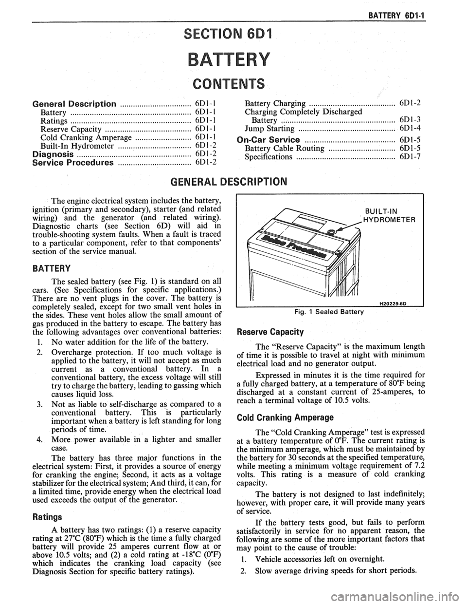
The sealed battery (see Fig. 1) is standard on all
cars. (See Specifications for specific applications.)
There are no vent plugs in the cover. The battery is
completely sealed, except for two small vent holes in
the sides. These vent holes allow the small amount of
gas produced in the battery to escape. The battery has
the following advantages over conventional batteries:
1. No water addition for the life of the battery.
2. Overcharge protection. If too much voltage is
applied to the battery, it will not accept as much
current as a conventional battery. In a
conventional battery, the excess voltage will still
try to charge the battery, leading to gassing which
causes liquid loss.
3. Not as liable to self-discharge as compared to a
conventional battery. This is particularly
important when a battery is left standing for long
periods of time.
4. More power available in a lighter and smaller
case.
The battery has three major functions in the
electrical system: First, it provides a source of energy
for cranking the engine; Second, it acts as a voltage
stabilizer for the electrical system; And third, it can, for
a limited time, provide energy when the electrical load
used exceeds the output of the generator.
Ratings
A battery has two ratings: (1) a reserve capacity
rating at 27°C (80°F) which is the time a fully charged
battery will provide 25 amperes current flow at or
above 10.5 volts; and (2) a cold rating at -18°C (0°F)
which indicates the cranking load capacity (see
Diagnosis Section for specific battery ratings).
BUILT-IN
HYDROMETER
Fig. 1 Sealed Battery
Reserve Capacity
The "Reserve Capacity" is the maximum length
of time it is possible to travel at night with minimum
electrical load and no generator output.
Expressed in minutes it is the time required for
a fully charged battery, at a temperature of 80°F being
discharged at a constant current of 25-amperes, to
reach a terminal voltage of 10.5 volts.
Cold Cranking Amperage
The "Cold Cranking Amperage" test is expressed
at a battery temperature of
0°F. The current rating is
the minimum amperage, which must be maintained by
the battery for 30 seconds at the specified temperature,
while meeting a minimum voltage requirement of 7.2
volts. This rating is a measure of cold cranking
capacity.
The battery is not designed to last indefinitely;
however, with proper care, it will provide many years
of service.
If the battery tests good, but fails to perform
satisfactorily in service for no apparent reason, the
following are some of the more important factors that
may point to the cause of trouble:
1. Vehicle
accessories left on overnight.
2. Slow
average driving speeds for short periods.
Page 588 of 1825
DRIVEABILITY AND EMISSIONS - S.0L (VIN E) 6EZ-C2-13
"THROTTLE BODY INJECTION (TBI) UNIT
Replacement (Figure C2-18)
a Remove or Disconnect
1. THERMAC hose from engine fitting.
2. Electrical connectors to IAC valve, TPS and fuel
injectors.
3. Grommet with wires from throttle body.
4. Throttle linkage, return
spring(s) transmission
control cable and cruise control (wherever
applicable).
5. Vacuum hoses (noting position of hoses) and
bracket.
6. Fuel inlet and return lines (use back-up wrench
J-29698-A or BT-8251-A). Discard o-
rings from
nuts.
7. TBI mounting hardware.
8. TBI flange (manifold mounting) gasket and
discard.
NOTICE: Stuff manifold opening with a rag to
prevent material from entering
engine, and remove old gasket
material from surface of intake
manifold.
Inspect
@ Intake manifold bore for loose parts and foreign
material, etc.
@ Intake manifold sealing surface for cleanliness.
Install or Connect
1. New TBI flange (manifold mounting) gasket.
2.
TI31 with mounting hardware.
Tighten
@ Hardwareto, 16.5N-m( 12Ib. ft.).
3. New o-rings on fuel line nuts
4. Fuel inlet and outlet lines.
Tighten - @ To 23 N.m (17 lb. ft.). (Use back-up wrench
J-29698-A or BT-8251-A to keep TBI nuts
from turning.)
5. Vacuum hoses and bracket.
6. Throttle linkage, return
spring(s) transmission
control cable and cruise control (wherever
applicable).
7. Grommet with wire harness to throttle body.
8. Electrical connectors, making sure connectors are
fully seated and latched.
9. Check to see if accelerator pedal is free by
depressing pedal to the floor
and releasing while
engine is "OFF".
10. With engine "OFF," and ignition "ON," check for
leaks around fuel line nuts.
11. Start engine and check for fuel leaks.
FUEL HOSEIPIPE ASSEMBLIES
Materials
Fuel Lines. These are welded steel tubes, meeting GM
Specification 124-M, or its equivalent. The fuel feed
line is
318" diameter, and the fuel return line is 5/16"
diameter. Do not use copper or aluminum tubing to
replace steel tubing. Those materials do not have
satisfactory durability to withstand normal vehicle
vibr, ii t' lon.
Clamps. These are stainless steel, screw band type
clamps,
#249472, or equivalent.
Coupled Hose. These are not to be repaired and are
replaced
&as an assembly.
Uncoupled Hose. Use only reinforced fuel resistant
hose, made of "fluroelastomer" material.
[lo not use w
hose within 4 inches (100 mm) of any part of the
exhaust system, or within 10 inches
(254 mm) of the
catalytic converter. The hose's inside diameter nus st
match the outside diameter of the steel tubing.
Fuel Line Repair
1. Cut
a piece of fuel hose 4 inches (100 mm) longer
than the section of line to be removed. If
more
than 6 inches (152 tnm) is to be removed, use a .
combination of steel pipe and hose. The
hose
length should not be more than 10 inches total.
2. Cut a section of pipe to be replacccl, with a tube
cutter. C'se the first step of a double flaring tool to
form a bead on the ends
of the pipe and also, on the
new section of pipe, if used.
3. Slide
the hose
clanlps onto the pip2 and push the
hose
2 inches (51 mm) onto each portion of the fuel
pipe. Tighten a
clamp on each side of the repair.
4. Secure
fuel line to the frame.
FUEL PUMP RELAY
(Figure
CZ-19)
The fuel pump relay is mounted in the engine
compartment. Other than checking for loose
connectors, the only service possible is replacement.
OIL PRESSURE SWITCH
(Figure C2-20)
The oil pressure switch is li~ounted on the engine.
This switch is a parallel power supply, with the fuel
pump relay, and will provide battery voltage to the
fuel
pump, after approximately 28 kPa (4 psi) oil
pressure is reached.
Page 758 of 1825
DRIVEABILITY AND EMISSIONS 2.8L (VIN 5) 6E3-C3-1
SECTION C3
EVAPORATIVE EMlSSlON CON"TOL SYSTEM (EECS)
CONTENTS
GENERAL DESCRIPTION ............... C3-1 DIAGNOSIS ........................ C3-2
PURPOSE ........................ C3-1 VISUAL CHECK OF CANISTER .......... 63-2
VAPOR CANISTER ................... C3-1 FUNCTIONAL TEST
EVAPORATIVE EMISSION SYSTEM
...... C3-1 Vapor Canister Purge Valve ........ C3-2
TANK PRESSURE CONTROLVALVE ...... C3-2 Fuel Tank Pressure Control Valve ..... C3-2
RESULTS OF INCORRECT OPERATION .... C3-2 ON-CAR SERVICE .......*+........ C3-3
FUEL VAPOR CANISTER R/R ............ C3-3
FUEL VAPOR CANISTER SOLENOID RIR.. .. C3-3
CANISTERHOSES.................... C3-3
................ PARTS INFORMATION C3-3
GENERAL DESCRIPTION
PURPOSE
The basic Evaporative Emission Control System
(EECS) used on all vehicles is the charcoal canister
storage method. This method transfers fuel vapor from
the fuel tank to an activated carbon (charcoal) storage
device (canister) to hold the vapors when the vehicle is
not operating. When the engine is running, the fuel
vapor is purged from the carbon element by intake air
flow and consumed in the normal combustion process.
VAPOR CANISTER
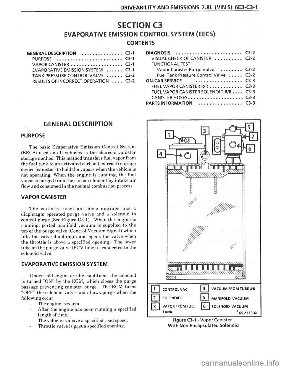
The canister used on these engines has a
diaphragm operated purge valve and a solenoid to
control purge (See Figure
C3-I). When the engine is
running, ported manifold vacuum is supplied to the
top of the
purge valve (Control Vacuum Signal) which
lifts the valve
diaphragm and opens the valve when
the throttle is above a specified opening.
The lower
tube on the purge
valve (PCV tube) is connected to the
solenoid valve.
EVAPORATIVE EMISSION SYSTEM
Under cold engine or idle conditions, the solenoid
is turned
"ON" by the ECM, which closes the purge
passage preventing canister purge.
'L'he ECM turns
"OFF" the solenoid valve and allows purge when the
following occur:
- 'I'he engine is warm.
- After the engine has been running a specified
length of time.
- 'I'he vehicle is above a specified road speed.
- Throttle valve is past a specified opening.
I CONTROL VAC Ifj VACUUM FROM TUBE #6
SOLENOID [ZI MANIFOLD VACUUM
a VAPOR FROM FUEL a SOLENOID VACUUM
TANK
"6s 2733-6E
Fiqure C3-1 - Vapor Canister
with Non-~nca~silated Solenoid
Page 759 of 1825
6E3-C3-2 2.8L (VIN S) DRIVEABILITY AND EMISSIONS
The "CONTROL VAC" tube on the purge valve of the
canister is connected to a ported vacuum source.
When the engine is above idle speed, sufficient
vacuum is available to open the purge valve
diaphragm. Vapors are purge through the solenoid to
the combustion chamber.
This system also has a Tank Pressure Control
Valve to control the flow of vapors to the canister.
TANK PRESSURE CONTROL VALVE
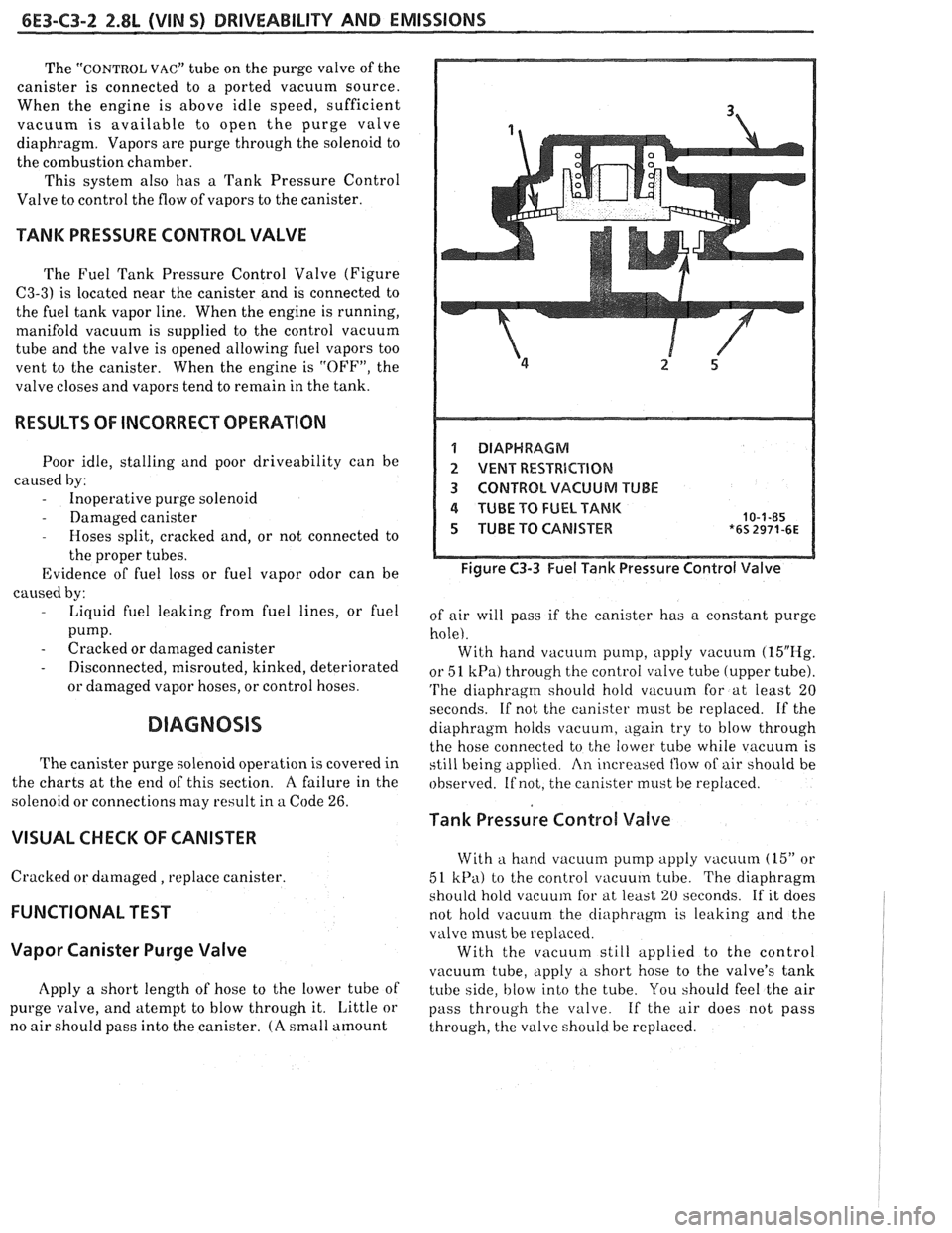
The Fuel Tank Pressure Control Valve (Figure
C3-3) is located near the canister and is connected to
the fuel tank vapor line. When the engine is running,
manifold vacuum is supplied to the control vacuum
tube and the valve is opened allowing
fuel vapors too
vent to the canister. When the engine is "OFF", the
valve closes and vapors tend to remain in the tank.
RESULTS OF INCORRECT OPERATION
Poor idle, stalling and poor driveability can be
caused by:
- Inoperative purge solenoid
- Damaged canister - Hoses split, cracked and, or not connected to
the proper tubes.
Evidence of fuel loss or fuel vapor odor can be
caused by:
- Liquid fuel leaking from fuel lines, or fuel
pump.
- Cracked or damaged canister
- Disconnected, misrouted, kinked, deteriorated
or damaged vapor hoses, or control hoses.
DIAGNOSIS
The canister purge solenoid operation is covered in
the charts
at the end of this section. A failure in the
solenoid or connections may result in a Code
26.
VISUAL CHECK OF CANISTER
Cracked or damaged, replace canister.
FUNCTIONAL TEST
Vapor Canister Purge Valve
Apply a short length of hose to the lower tube of
purge valve, and atempt to blow through it. Little or
no air should pass into the canister.
(A small amount
1 DIAPHRAGM
2 VENT RESTRBCBIQN
3 CONTROL VACUUM TUBE
4 TUBE TO FUEL TANK 10-1-85 5 TUBE TO CANISTER *6s 2971-6~
Figure C3-3 Fuel Tank Pressure Control Valve
of air will pass if the canister has a constant purge
hole). With hand vacuum pump, apply vacuum
(15"E-Ig.
or 51 kPa) through the control valve tube (upper tube).
'I'he diaphragm should hold vacuum for at least 20
seconds. If not the canister must be replaced. If the
diaphragm holds
vacuu111, again try to blow through
the hose connected to the lower tube while vacuum is
still being applied
An increased flow of air should be
observed. If not, the canister must be replaced.
Tank Pressure Control Valve
With a hand vacuum pump apply vacuum (15" or
51
kPa) to the control vacuum tube. The diaphragm
shoi~ld hold vacuum for at least 20 seconds. If it does
not hold vacuum the
cliaphragnl is leaking and the
valve must be replaced.
With the vacuum still applied to the control
vacuum tube, apply
a short hose to the valve's tank
tube side,
blow into the tube. You should feel the air
pass through the valve. If the
air does not pass
through, the valve should be replaced.
Page 911 of 1825
6E3-C3-2 5.OL (VIN F) & 5.7L (WIN 8) DRIVEABILITY AND EMISSIONS
The ECM turns "ON" the solenoid valve and allows
purge when:
@ Above a specified road speed.
r Engine is warm
@ After the engine has been running a specified
time.
@ Above a specified throttle opening.
This
is an ECM feedback system that increases
purge until the ECM senses a rich condition from the
O2 sensor. The purge is then regulated until the ECM
no longer receives
a rich signal from the O2 sensor.
This system uses an in-tank pressure control valve to
control the flow of vapors from the fuel tank to the
canister.
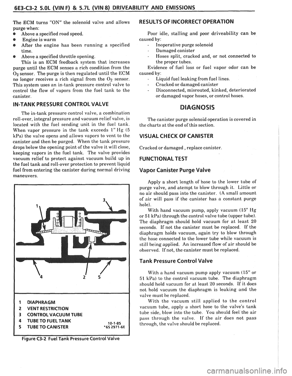
IN-TANK PRESSURE CONTROL VALVE
The in-tank pressure control valve, a combination
roll-over, integral pressure and vacuum relief valve, is
located with the fuel sending unit in the fuel tank.
When vapor pressure in the tank exceeds
1" Hg (5
kPa) the valve opens and allows vapors to vent to the
canister and then be purged. When the tank pressure
drops below the opening point of the valve it will close,
keeping vapors in the fuel tank. The valve provides
vacuum relief to protect against vacuum build up in
the fuel tank and roll-over protection to prevent liquid
fuel from entering the canister during normal driving
maneuvers.
1 DIAPHRAGM
2 VENT RESTRICTION
3 CONTROL VACUUM TUBE
4 TUBE TO FUEL TANK 10-1-85 5 TUBE TO CANISTER *6s 2971-6~
RESULTS OF INCORRECT OPERATION
Poor idle, stalling and poor driveability can be
caused by:
- Inoperative purge solenoid
- Damaged canister
- Hoses split, cracked and, or not connected to
the proper tubes.
Evidence of fuel loss or fuel vapor odor can be
caused by:
- Liquid fuel leaking from fuel lines.
- Cracked or damaged canister
- Disconnected, misrouted, kinked, deteriorated
or damaged vapor hoses, or control hoses.
DIAGNOSIS
The canister purge solenoid operation is covered in
the charts at the end of this section.
VISUAL CHECK OF CANISTER
Cracked or damaged, replace canister.
FUNCTIONAL TEST
Vapor Canister Purge Valve
Apply a short length of hose to the lower tube of
purge valve, and atempt to blow through it. Little or
no air should pass into the canister.
(A small amount
of air will pass if the canister has a constant purge
hole). With hand vacuum pump, apply vacuum
(15" Hg
or 51 kPa) through the control valve tube (upper tube).
The diaphragm should hold vacuum for at least
20
seconds. If not the canister must be replaced. If the
diaphragm holds vacuum, again try to blow through
the hose connected to the lower tube while vacuum is
still being applied. An increased flow of air should be
observed. If not, the canister must be replaced.
Tank Pressure Control Valve
With a hand vacuum pump apply vacuum (15" or
51 kPa) to the control vacuum tube. The diaphragm
should hold vacuum for at least
20 seconds. If it does
not hold vacuum the diaphragm is leaking and the
valve must be replaced.
With the vacuum still applied to the control
vacuum tube, apply a short hose to the valve's tank
tube side, blow into the tube. You should feel the air
pass through the valve. If the air does not pass
through, the valve should be replaced.
Figure C3-2 Fuel Tank Pressure Control Valve
Page 1000 of 1825
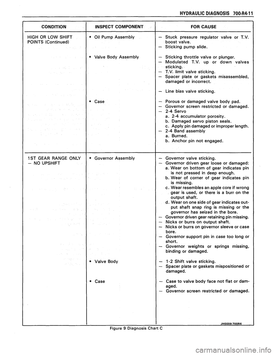
HYDRAULIC DIAGNOSIS 700-R4-I 1
CONDITION I INSPECT COMPONENT
HIGH OR LOW SHIFT
POINTS (Continued) 0 Oil Pump Assembly
0 Valve Body Assembly
Case
Valve Body
- Stuck pressure regulator valve or T.V.
boost valve.
- Sticking pump slide.
- Sticking throttle valve or plunger.
- Modulated T.V. up or down valves
sticking.
- T.V. limit valve sticking. - Spacer plate or gaskets misassembled,
damaged or incorrect.
I - Line bias valve sticking.
- Porous or damaged valve body pad.
- Governor screen restricted or damaged.
- 2-4 Servo
a. 2-4 accumulator porosity.
b. Damaged servo piston seals.
c. Apply pin damaged or improper length.
- 2-4 Band assembly
a. Burned.
b. Anchor pin not engaged.
- Governor valve sticking. - Governor driven gear loose or damaged:
a. Wear on bottom of gear indicates pin
is not pressed in deep enough.
b. Wear of corner of gear indicates pin
is missing.
c. Wear resembles an apple core if wrong
gear is used, or there is a burr on the
output shaft.
d. Wear on one side of gear indicates out-
put shaft snap ring is missing or the
governor has seized in the bore.
- Governor driven gear retaining pin missing.
- Nicks or burrs on output shaft.
- Nicks or burrs on governor sleeve or case
bore.
- Governor support pin in case too long or
short.
- Governor weights or springs missing,
binding or damaged.
- 1-2 Shift valve sticking. - Spacer plate or gaskets mispositioned or
damaged.
- Case to valve body face not flat or dam-
aged.
- Governor screen restricted or damaged.
Figure 9 Diagnosis Chart C
Page 1052 of 1825
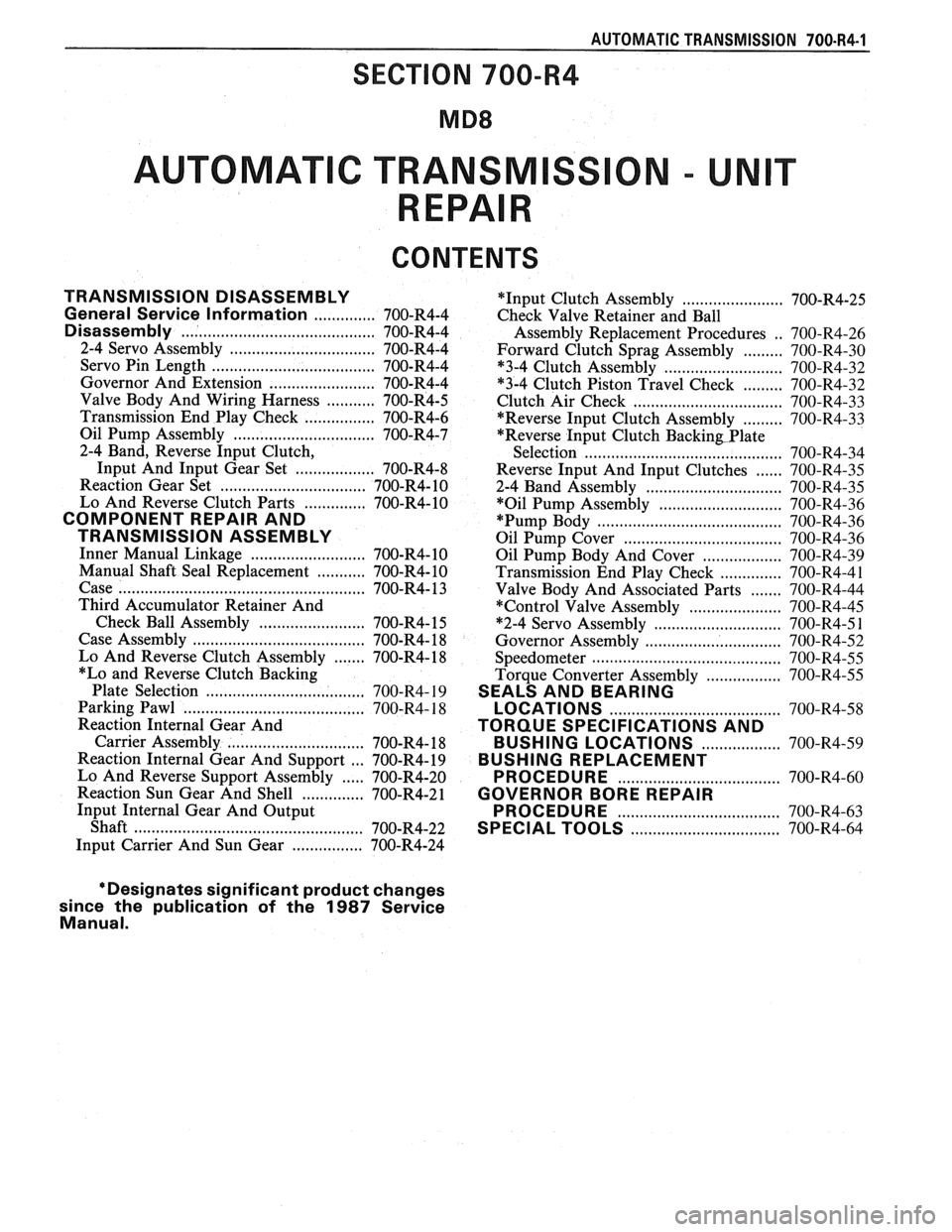
AUTOMATIC TRANSMISSION 700-R4-1
AUTOMAT C TRANSM
CONTENTS
TRANSMISSION DISASSEMBLY
.............. General Service Information 700-R4-4
........................................... Disassembly 700-R4-4
2-4 Servo Assembly
................................. 700-R4-4
.................................. Servo Pin Length 700-R4-4
........................ Governor And Extension 700-R4-4
Valve Body And Wiring Harness
........... 700-R4-5
................ Transmission End Play Check 700-R4-6
Oil Pump Assembly
................................ 700-R4-7
2-4 Band. Reverse Input Clutch.
.................. Input And Input Gear Set 700-R4-8
Reaction Gear Set
................................. 700-R4- 10
.............. Lo And Reverse Clutch Parts 700-R4-10
COMPONENT REPAIR AND
TRANSMISSION ASSEMBLY
Inner Manual Linkage .......................... 700-R4- 10
........... Manual Shaft Seal Replacement 700-R4-10
Case
...................................................... 700-R4- 13
Third Accumulator Retainer And
Check Ball Assembly
........................ 700-R4- 15
Case Assembly
............................. ., ...... 700-R4- 18
Lo And Reverse Clutch Assembly
....... 700-R4- 18
*Lo and Reverse Clutch Backing
Plate Selection
.................................. 700-R4- 19
..................................... Parking Pawl 700-R4- 18
Reaction Internal Gear And
Carrier Assembly
.............................. 700-R4- 18
Reaction Internal Gear And Support
... 700-R4- 19
Lo And Reverse Support Assembly
..... 700-R4-20
Reaction Sun Gear And Shell
.............. 700-R4-21
Input Internal Gear And Output
.................. Shaft .......................... ... 700-R4-22
................ Input Carrier And Sun Gear 700-R4-24 *Input
Clutch Assembly
....................... 700-R4-25
Check Valve Retainer and Ball
Assembly Replacement Procedures
. . 700-R4-26
Forward Clutch Sprag Assembly
......... 700-R4-30
*3-4 Clutch Assembly
.......................... 700-R4-32
......... "3-4 Clutch Piston Travel Check 700-R4-32
Clutch Air Check
................................. 700-R4-33
......... *Reverse Input Clutch Assembly 700-R4-33
"Reverse Input Clutch
Backin~Plate
Selection ...................................... 700-R4-34
Reverse Input And Input Clutches
...... 700-R4-35
2-4 Band Assembly
.............................. 700-R4-35
*Oil Pump Assembly
............................ 700-R4-36
"Pump Body .......................................... 700-R4-36
Oil Pump Cover
.................................... 700-R4-36
Oil Pump Body And Cover
.................. 700-R4-39
Transmission End Play Check
.............. 700-R4-4 1
....... Valve Body And Associated Parts 700-R4-44
*Control Valve Assembly
..................... 700-R4-45
*2-4 Servo Assembly
............................. 700-R4-5 1
Governor Assembly ............................... 700-R4-52
........................................... Speedometer 700-R4-55
Torque Converter Assembly
................. 700-R4-55
SEALS AND BEARING
....................................... LOCATIONS 700-R4-58
TORQUE SPECIFICATIONS AND
.................. BUSH l NG LOCATIONS 700-R4-59
BUSHING REPLACEMENT
..................................... PROCEDURE 700-R4-60
GOVERNOR BORE REPAIR
PROCEDURE
......................... ............ 700-R4-63
...... ...................... SPECIAL TOOLS .. 700-R4-64
*Designates significant product changes
since the publication of the
1987 Service
Manual .
Page 1055 of 1825
700.R4.4 AUTOMATIC TRANSMISSION
TRANSMISSION DISASSEMBLY
General Service Information
e Teflon Oil Seal Rings
If any seal rings are damaged, cut, or do not
rotate freely in their groove be certain to check
the ring groove for debris, burrs, or damage.
s Thrust Washer Surfaces
The thrust washer and thrust bearing surfaces
may appear to be polished. This is a normal
condition and should not be considered damage.
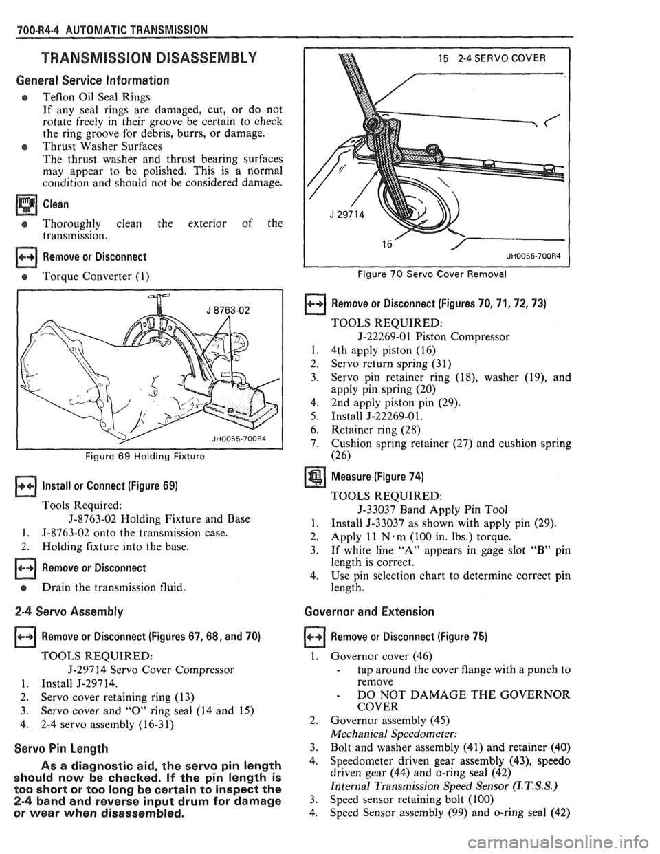
Thoroughly clean the exterior of the
transmission.
Remove or Disconnect
e 'Torque Converter (1)
I I Figure 69 Holding Fixture
Install or Connect (Figure 69)
Tools Required:
J-8763-02 Holding Fixture and Base
1. 5-8763-02 onto the transmission case.
2. Holding fixture into the base.
Remove or Disconnect
e Drain the transmission fluid.
2-4 Servo Assembly
Remove or Disconnect (Figures 67,68, and 70)
TOOLS REQUIRED:
J-297 14 Servo Cover Compressor
1. Install J-29714.
2. Servo cover retaining ring (13)
3. Servo cover and
"0" ring seal (14 and 15)
4. 2-4 servo assembly (16-31)
Servo Pin Length
As a diagnostic aid, the servo pin length
should now be checked.
If the pin length is
too short
or too long be certain to inspect the
2-4 band and reverse input drum for damage
or wear when disassembled.
15 2-4 SERVO COVER
Figure 70 Servo Cover Removal
Remove or Disconnect (Figures 70, 71,72,73)
TOOLS REQUIRED:
5-22269-01 Piston Compressor
1. 4th apply piston (16)
2. Servo return spring (31)
3. Servo pin
retainer ring
(18), washer (19), and
apply pin spring (20)
4, 2nd apply piston
pin (29).
5. Install J-22269-01.
6. Retainer ring
(28)
7. Cushion spring
retainer (27) and cushion spring
(26)
Measure (Figure 74)
TOOLS REQUIRED:
5-33037 Band Apply Pin Tool
1. Install 5-33037 as shown with apply pin (29).
2. Apply
1 1 N . m
(100 in. lbs.) torque.
3. If white line "A" appears in gage slot "B" pin
length is correct.
4. Use pin selection chart to determine correct pin
length.
Governor and Extension
Remove or Disconnect (Figure 75)
1. Governor cover (46)
- tap around the cover flange with a punch to
remove
- DO NOT DAMAGE THE GOVERNOR
COVER
2. Governor assembly (45)
Mechanical Speedometer:
3. Bolt and washer assembly (41) and retainer (40)
4. Speedometer driven gear assembly (43), speedo
driven gear (44) and o-ring seal (42)
Internal Transmission Speed Sensor
(I. T. S.S.)
3. Speed sensor retaining bolt (100)
4. Speed
Sensor assembly
(99) and o-ring seal (42)
Page 1057 of 1825
700.R4-6 AUTOMATIC TRANSMISSION
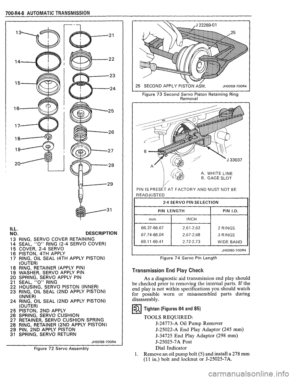
ILL. NO. DESCRIPTION
13 RING, SERVO COVER RETAINING
14 SEAL, "0" RING (2-4
SERVO COVER)
15 COVER, 2-4 SERVO
16 PISTON, 4TH APPLY 17 RING, OIL SEAL (4TH APPLY PISTON)
(OUTER)
18 RING, RETAINER (APPLY PIN)
19 WASHER, SERVO APPLY PIN
20 SPRING, SERVO APPLY PIN
21 SEAL,
"0" RING 22 HOUSING, SERVO PISTON (INNER) 23 RING, OIL SEAL (2ND APPLY PISTON)
(INNER)
24 RING, OIL SEAL
(2ND APPLY PISTON)
(OUTER)
25 PISTON, 2ND APPLY
26 SPRING, SERVO CUSHION
27 RETAINER, SERVO CUSHION SPRING
28 RING, RETAINER
(2ND APPLY PISTON)
29 PIN, 2ND APPLY PISTON 31 SPRING, SERVO RETURN
JH0058-700R4
Figure 72 Servo Assembly Figure
73 Second
Servo Piston Retaining Ring
Removal
A. WHITE LINE B GAGE SLOT
PIN IS PRESET AT FACTORY AND MUST NOT BE
I I 2-4 SERVO PIN SELECTION I I
I I PIN LENGTH 1 PIN I.D. 11
Figure 74 Servo Pin Length
Transmission End Play Check
As a diagnostic aid transmission end play should
be checked prior to removing the internal parts. If the
end play is not within specifications you should watch
for possible worn or misassembled parts during
disassembly.
Tighten (Figures 84 and 85)
TOOLS REQUIRED:
J-24773-A Oil Pump Remover
5-25022-A End Play Adaptor (245 mm)
5-34725 End Play Adaptor (298 mm)
5-25025-7A Post
Dial Indicator
1. Remove an oil pump bolt (5) and install a 278 mm
(11 in.) bolt and locknut or J-25025-7A.