length PONTIAC FIERO 1988 Service Owner's Guide
[x] Cancel search | Manufacturer: PONTIAC, Model Year: 1988, Model line: FIERO, Model: PONTIAC FIERO 1988Pages: 1825, PDF Size: 99.44 MB
Page 1102 of 1825
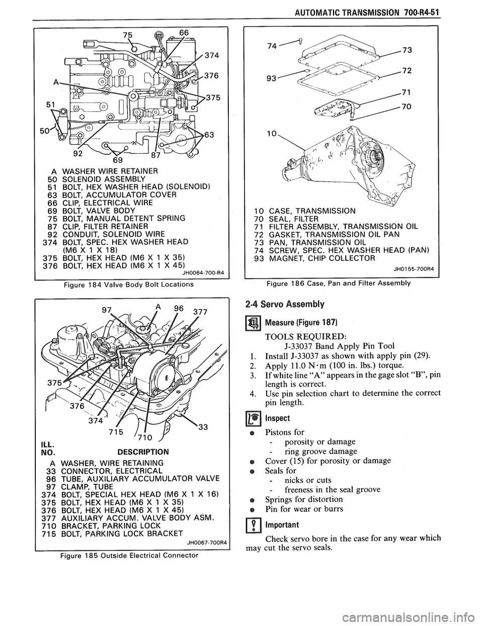
A WASHER WlRE RETAINER
50 SOLENOID ASSEMBLY
51 BOLT, HEX WASHER HEAD (SOLENOID)
63 BOLT, ACCUMULATOR COVER
66 CLIP, ELECTRICAL WlRE
69 BOLT, VALVE BODY
75 BOLT, MANUAL DETENT SPRING
87 CLIP, FILTER RETAINER
92 CONDUIT, SOLENOID WlRE
374 BOLT, SPEC. HEX WASHER HEAD
(M6 X 1 X
18)
375 BOLT, HEX HEAD (M6 X 1 X 35)
376 BOLT, HEX HEAD (M6 X 1 X 45) JH0064-700-R4
Figure 184 Valve Body Bolt Locations
ILL. .
NO. DESCRIPTION
A WASHER, WlRE RETAINING
33 CONNECTOR, ELECTRICAL
96 TUBE, AUXILIARY ACCUMULATOR VALVE
97 CLAMP, TUBE
374 BOLT, SPECIAL HEX HEAD (M6 X
1 X 16)
375 BOLT, HEX HEAD (M6 X 1 X 35)
376 BOLT, HEX HEAD (M6 X 1 X 45)
377 AUXILIARY ACCUM. VALVE BODY ASM.
710 BRACKET, PARKING LOCK
71 5 BOLT, PARKING LOCK BRACKET
JH0067-700R4
AUTOMATIC TRANSMISSION 700-R4-51
10 CASE, TRANSMISSION
70 SEAL, FILTER
7
1 FILTER ASSEMBLY, TRANSMISSION OIL
72 GASKET, TRANSMISSION OIL PAN
73 PAN, TRANSMISSION OIL
74 SCREW, SPEC. HEX WASHER HEAD (PAN)
93 MAGNET, CHIP COLLECTOR
JH0155-700R4
Figure 186 Case, Pan and Filter Assembly
2-4 Servo Assembly
Measure (Figure 187)
TOOLS REQUIRED:
J-33037 Band Apply Pin Tool
1. Install
J-33037 as
shown with apply pin (29).
2.
Apply 11.0 N-m (100 in. Ibs.) torque.
3. If
white line "A" appears in the gage slot
"B", pin
length is correct.
4. Use pin selection chart to determine the correct
pin length.
Inspect
a Pistons for
- porosity or damage
- ring groove damage
Cover (15) for porosity or damage
Seals for
- nicks or cuts
- freeness in the seal groove
a Springs for distortion
e Pin for wear or burrs
Important
Check servo bore in the case for any wear which
may cut the servo seals.
~'~ure 185 Outside Electrical Connector
Page 1103 of 1825
700-R4-52 AUTOMATIC TRANSMISSION
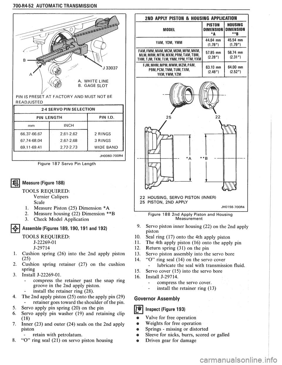
A. WHITE LINE B. GAGE SLOT
Figure 187 Servo Pin Length
Measure (Figure 188)
TOOLS REQUIRED:
Vernier Calipers
Scale
1. Measure Piston (25) Dimension
*A
2.
Measure housing (22) Dimension **B
3. Check Model Application
Assemble (Figures 189, 190, 191 and 192)
TOOLS REQUIRED:
5-22269-01
J-297 14
1. Cushion spring (26) into the 2nd apply piston
(25)
2. Cushion spring retainer (27) on the cushion
spring
3. Install J-22269-01.
- compress the retainer past the snap ring
groove in the 2nd apply piston.
- install the retainer ring (28).
4. The 2nd apply piston (25) onto the apply pin (29)
- retainer goes toward the shoulder of the pin.
5. Servo apply pin spring (20) on the pin
6. Servo apply pin washer (19) and retaining clip
(18)
7. Inner (23) and outer (24) seals on the 2nd apply
piston
- retain with petrolatum.
8. "0" ring seal (21) on servo piston housing
2ND APPLY PISTON & HOUSING APPLICATION
MODEL I DIMt!SION DIMENSION I **B I
I YAM, YOM, YMM I
MLM, MRM,MTM,MXM, PRM,TAM,TBM,
22 HOUSING, SERVO PISTON (INNER)
25 PISTON, 2ND APPLY
JH0156-700R4
Figure 188 2nd Apply Piston and Housing
Measurement
9. Servo piston inner housing (22) on the 2nd apply
piston
10. Seal ring (17) onto the 4th apply piston
11. The 4th apply piston (16) onto the apply pin
12. Return spring (31) on the pin
13. Servo piston assembly into the servo bore
14.
"0" ring seal (14) on the servo cover
- lubricate the seal with transmission fluid.
15. Servo cover (15) into the servo bore
16. Install J-297 14.
- compress the servo cover.
- install the retainer ring (13)
Governor Assembly
Inspect (Figure 193)
e Valve for free operation
e Weights for free operation
e Springs - missing or distorted
Sleeve for nicks, burrs, scored or galled
o Driven gear for damage
Page 1158 of 1825
CLUTCH 7C-4
SECTION 76
CLUTCH
CONTENTS
GENERAL DESCRIPTION .......................... .. ............................................................. 7C-I
DIAGNOSIS ...................................................................................................................... 7C-3
Preliminary Checks ....................... ... ............................................................................ 7C-2
Bleeding Hydraulic Clutch System ................... .. .......................................................... 7C-2
ON-VEHICLE SERVICE ................................................................................................. 7C-5
Clutch Hydraulic System ................................................................................................. 7C-5
..................... Pressure Plate and Disc .. ........................................................................... 7C-6
Clutch Pedal ..................................................................................................................... 7C-6
Pilot Bearing .................................................................................................................. 7C-6
....................................................................................................... SPECIFICATIONS 7C-8
............................................................................................................ SPECIAL TOOLS 7C-8
GENERAL DESCRIPTION
COMPONENTS
The principal parts of a clutch system are: the
driving member and the operating members. Figure
7C-1 shows an exploded view of the clutch system.
DRIVEN MEMBERS (FIGURES 7C-1 AND 7C-2)
The driven member is the clutch disc with a
splined hub which is free to slide lengthwise along the
splines of the input shaft, but which drives the input
shaft through these same splines.
The driving and driven members are held in
contact by spring pressure. This pressure is exerted by
a diaphragm spring in the pressure plate assembly.
HYDRAULIC CLUTCH (FIGURE 7C-3)
A hydraulic clutch operating mechanism is used
on all models. The
mechanism consist of a remote
reservoir, clutch master cylinder and slave cylinder.
The remote reservoir is mounted to a bracket which
bolts to the power brake booster. The clutch master
cylinder is mounted on the cowl panel and the slave
cylinder is mounted on the bell housing. The clutch
master cylinder is operated directly off the clutch
pedal.
When the clutch pedal is pressed down, hydraulic
fluid under pressure from the clutch master cylinder
flows into the slave cylinder. Since the piston is also
connected to the clutch fork this lever moves the
release bearing into contact with the clutch cover
release fingers to disengage the clutch. The hydraulic
clutch system locates the clutch pedal height and
provides automatic clutch adjustment. No adjustment
of clutch linkage or pedal position is required.
OPERATING MEMBERS (FIGURE 7C-3)
HYDRAULIC CLUTCH FLUID
When adding fluid to or refilling the system after
The clutch release system is operated by service operations use GM Delco Supreme No. 11 hydraulic pressure and consists of the clutch pedal, brake fluid or an equivalent fluid that meets DOT 3 clutch master cylinder, clutch slave cylinder, clutch specifications. fork and clutch release bearing.
NOTICE: Do not use mineral or paraffin base oil in
the Clutch Hydraulic System. These fluids will
damage the rubber parts in the cylinders.
Page 1170 of 1825
These schematics break the entire electrical
system down into individual circuits. You are
not distracted by wiring which is not part of
the circuit you're working on.
It is important to realize that no attempt is
made on the schematic to represent compo-
nents and wiring as they physically appear on
the car. For example, a 4-foot length of wire is
treated no differently in a schematic from one
which is only a few inches long. The number of
cavities for each connector is listed in the Com-
ponent Location List. Similarly, switches and
other components are shown as simply as pos-
sible, with regard to function only.
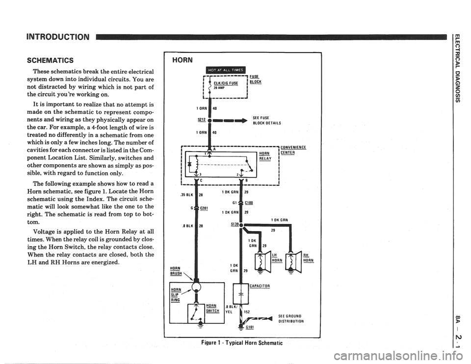
The following example shows how to read a
Worn schematic, see figure
1. Locate the Horn
schematic using the Index. The circuit sche-
matic will look somewhat like the one to the
right. The schematic is read from top to bot-
tom.
Voltage is applied to the Horn Relay at all
times. When the relay coil is grounded by clos-
ing the Horn Switch, the relay contacts close.
When the relay contacts are closed, both the
LH and
RH Horns are energized.
1 HORN
SEE FUSE
I BLOCK DETAILS
Figure 1 - Typical Horn Schematic
Page 1188 of 1825
REPAIR PROCEDURES
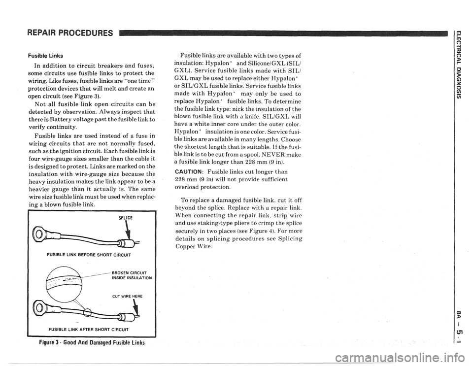
Fusible Links
In addition to circuit breakers and fuses,
some circuits use fusible links to protect the
wiring. Like fuses, fusible links are "one time
"
protection devices that will melt and create an
open circuit (see Figure
3).
Not all fusible link open circuits can be
detected by observation. Always inspect that
there is Battery voltage past the fusible link to
verify continuity.
Fusible links are used instead of a fuse in
wiring circuits that are not normally fused,
such as the ignition circuit. Each fusible link is
four wire-gauge sizes smaller than the cable it
is designed to protect. Links are marked on the
insulation with wire-gauge size because the
heavy insulation makes the link appear to be a
heavier gauge than it actually is. The same
wire size fusible link must be used when replac-
ing a blown fusible link.
FUSIBLE LINK BEFORE SHORT CIRCUIT
, BROKEN CIRCUIT INSIDE INSULATION
Fusible links are available with two types of
insulation: Hypalon
bnd SiliconelGXL (SILI
GXL). Service fusible links made with SILI
GXL may be used to replace either Hypalon "
or SILIGXL fusible links. Service fusible links
made with
Hypalonday only be used to
replace Hypalon
"fusible links. To determine
the fusible link type: nick the insulation of the
blown fusible link with a knife.
SILIGXL will
have a white inner core under the outer color.
Hypalon
"nsulation is one color. Service fusi-
ble links are available in many lengths. Choose
the shortest length that is suitable.
If the fusi-
ble link is to be cut from a spool, NEVER make
a fusible link longer than 228 mm
(9 in).
CAUTION: Fusible links cut longer than
228 mm
(9 in) will not provide sufficient
overload protection.
To replace a damaged fusible link, cut it off
beyond the splice. Replace with a repair link.
When connecting the repair link. strip wire
and use staking-type pliers to crimp the splice
securely in two places (see Figure
4). For more
details on splicing procedures see Splicing
Copper Wire.
R SHORT CIRCUIT
Figure 3 - Good And Damaged Fusible Links
-- - - - - -- - - - - -- - - -
Page 1189 of 1825
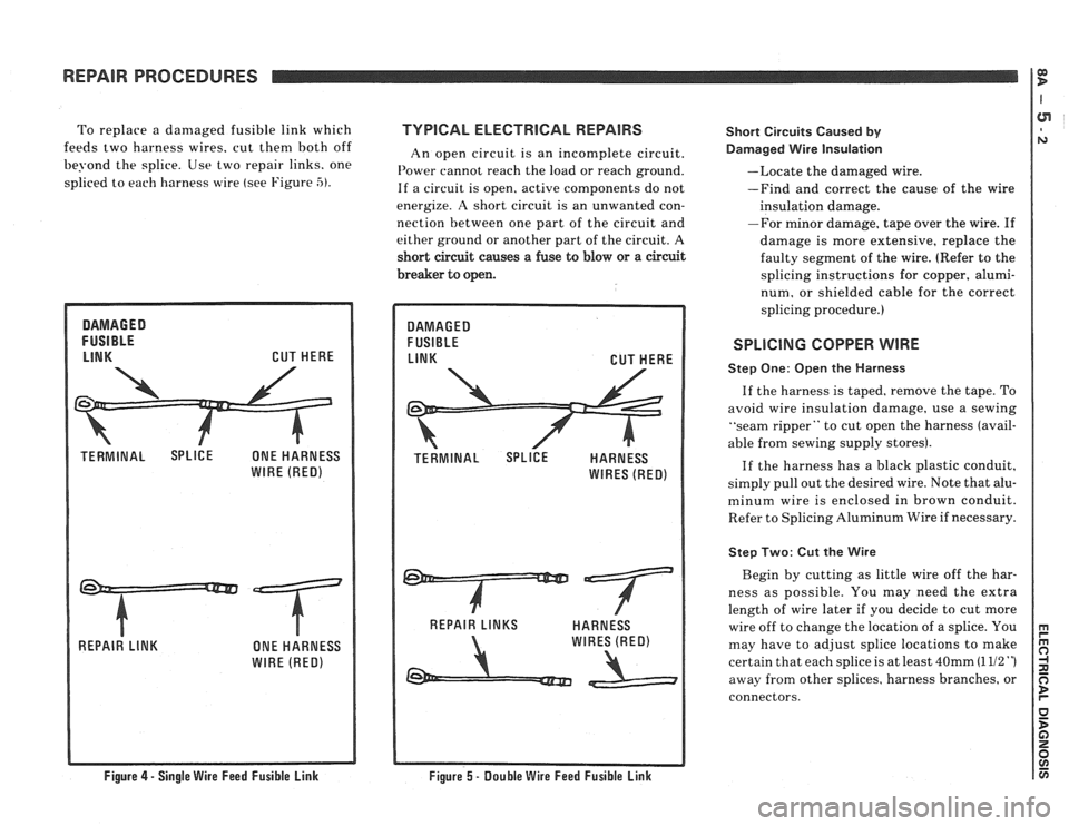
To replace a damaged fusible link which TVPlCAL ELECTRlCAL REPAIRS
feeds two harness wires. cut then1 both off
An open circuit is an incomplete circuit.
be?-ond the splice. Use two repair links. one I'ower cannot reach the load or reach ground.
spliced to each harness wire (see Figure -5). If a circuit is open. active components do not
energize.
A short circuit is an unwanted con-
nection between one part of the circuit and
either ground or another part of the circuit. A
short circuit causes
a fuse to blow or a circuit
breaker to open. Short
Circuits Caused
by
Darnaged Wire Insulation
--Locate the damaged wire.
-Find and correct the cause of the wire
insulation damage.
-For minor damage, tape over the wire.
If
damage is more extensive, replace the
faulty segment of the wire. (Refer to the
splicing instructions for copper, alumi-
num, or shielded cable for the correct
splicing procedure.)
REPAIR PROCEDURES
SPLICING COPPER WIRE
Q) D
Step One: Open the Harness
If the harness is taped, remove the tape. To
avoid wire insulation damage, use a sewing
"seam ripper" to cut open the harness (avail-
able from sewing supply stores).
If the harness has a black plastic conduit,
simply pull out the desired wire. Note that alu-
minum wire is enclosed in brown conduit.
Refer to Splicing Aluminum Wire if necessary.
Step Two: Cut the Wire
Begin by cutting as little wire off the har-
ness as possible. You may need the extra
length of wire later if you decide to cut more
wire off to change the location of a splice. You
may have to adjust splice locations to make
certain that each splice is at least
40mm (1 112 ")
away from other splices, harness branches, or
connectors.
Figure 4 - Single Wire Feed Fusible Link
Figure 5 - Double Wire Feed Fusible Link
Page 1190 of 1825
REPAIR PROCEDURES
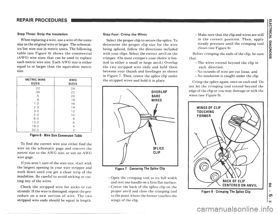
Step Three: Strip the Insulation
When replacing a wire. use a wire of the same
size as the original wire or larger. The schemat-
ics list wire size in metric units. The following
table (see Figure
6) shows the commercial
(AWG) wire sizes that can be used to replace
each
metric wire size. Each AWG size is either
equal to or larger than the equivalent metric
size.
METRIC WIRE
SIZES
.22
.35
.5
.8
13.0
32.0
AWG
SIZES
Figure 6 - Wire Size Conversion Table
To find the correct wire size either find the
wire on the schematic page and convert the
metric size to the AR'G size. or use an
An'(;
wire gage.
If you aren't sure of the wire size. start with
the largest opening in your wire stripper and
work down until you get a clean strip of the
insulation. Be careful to avoid nicking or cut-
ting any of the wires.
Check the stripped wire for nicks or cut
strands. If the wire is damaged. repeat the pro-
cedure on a new section of wire. The two
stripped wire ends should be equal in length.
Step Four: Crirnp the Wires
Select the proper clip to secure the splice. '1'0
determine the proper clip size for the wire
heing spliced. follow the directions included
with your clips. Select the correct anvil on the
crimper. (On most crimpers your choice is
lim-
ited to either a small or large anvil.) Overlap
the two stripped wire ends and hold them
between your
thumb and forefinger as shown
in Figure
7. Then, center the splice clip under
the stripped wires and hold it in place.
-Open the crimping tool to its full width
and rest one handle on a firm flat surface.
--Center the back of the splice clip on the
proper
anvil and close the crinlping tool
to the point where the former touches the
wings of the clip. -Make
sure that the clip and wires are still
in the correct position. Then, apply
steady pressure until the crimping tool
closes (see Figure
8).
Before crimping the ends of the clip, be sure
that:
--The wires extend beyond the clip in
each direction.
-No strands of wire are cut loose, and
-No insulation is caught under the clip.
Crirnp the splice again. once on each end. Do
not let the crimping tool extend beyond the
edge of the clip or you may damage or nick the
wires (see Figure
9).
/ CENTERED ON ANVIL
Figure 8 - Crimping The Splice Clip
Page 1192 of 1825
REPAIR PROCEDURES
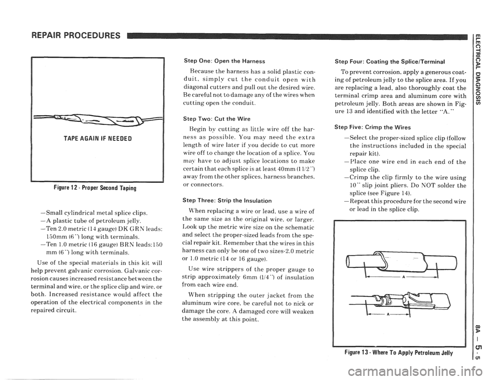
TAPE AGAIN IF NEEDED
Figure
12 - Proper Second Taping
-Small cylindrical metal splice clips.
-A plastic tube of petroleum jelly.
-Ten 2.0 metric
(14 gauge) DK GRN leads:
lv50mm (6 "1 long with terminals.
-Ten 1.0 metric
( 16 gauge) BRN leads: 150
mm
(6") long with terminals.
Use of the special materials in this kit will
help prevent galvanic corrosion. Galvanic
ror-
rosion causes increased resistance between the
terminal and wire. or the splice clip and wire. or
both. Increased resistance would affect the
operation of the electrical components in the
repaired circuit.
Step One: Open the Harness
Because the harness has a solid plastic con-
duit. simply cut the conduit open with
diagonal cutters and pull out the desired wire.
Be careful not to damage any of the wires when
cutting open the conduit.
Step Two: Cut the Wire
Begin by cutting as little wire off the har-
ness as possible. You may need the extra
length of wire later if you decide to cut more
wire off to change the location of a splice. You
ma?. have to adjust splice locations to make
certain that each splice is at least 40mm
(1 112")
away from the other splices. harness branches.
or connectors.
Step Three: Strip the Insulation
When replacing a wire or lead. use a wire of
the same size as the original wire, or larger.
Look up the metric wire size on the schematic
and select the proper-sized leads from the spe-
cial repair kit. Remember that the wires in this
harness can only be one of two sizes-2.0 metric
or 1.0 metric
(14 or 16 gauge).
Use wire strippers of the proper gauge to
strip approximately 6mm (114
") of insulation
from each wire end.
When stripping the outer jacket from the
aluminum wire core. be careful not to nick or
damage the core.
A damaged core will weaken
the assembly at this point.
Step Four: Coating the SpliceITerminal
To prevent corrosion, apply a generous coat-
ing of petroleum jelly to the splice area.
If you
are replacing a lead, also thoroughly coat the
terminal crimp area and aluminum core with
petroleum jelly. Both areas are shown in Fig-
ure
13 and identified with the letter "A."
Step Five: Crimp the Wires
-Select the proper-sized splice clip (follow
the instructions included in the special
repair kit).
-Place one wire end in each end of the
splice clip.
-Crimp the clip firmly to the wire using
10" slip joint pliers. Do NOT solder the
splice (see Figure 14).
-Repeat this procedure for the second wire
or lead in the splice clip.
Figure 13 - Where To Apply Petroleum Jelly
Page 1344 of 1825
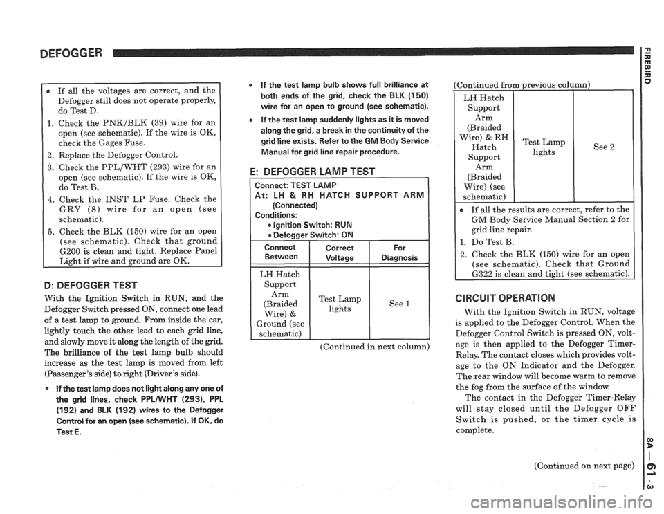
DEFOGGER
r If all the voltages are correct, and the
Defogger still does not operate properly,
do Test D.
1. Check the PNK/BLK (39) wire for an
open (see schematic). If the wire is OK,
check the Gages Fuse.
2. Replace the Defogger Control.
3. Check the PPL/WHT (293) wire for an
open (see schematic). If the wire is OK,
do Test B.
4. Check the INST LP Fuse. Check the
GRY
(8) wire for an open (see
schematic).
5. Check the BLK (150) wire for an open
(see schematic). Check that ground
6200 is clean and tight. Replace Panel
Light if wire and ground are OK.
D: DEFOGGER TEST
With the Ignition Switch in RUN, and the
Defogger Switch pressed
ON, connect one lead
of a test lamp to ground. From inside the car,
lightly touch the other lead to each grid line,
and slowly move it along the length of the grid.
The brilliance of the test lamp bulb should
increase as the test lamp is moved from left
(Passenger's side) to right (Driver's side).
0 If the test lamp does not light along any one of
the grid lines, check
PPLIWHT (2931, PPL
(192) and BLK (192) wires to the Defogger
Control for an open
(see schematic). If OK, do
Test
E.
If the test lamp bulb shows full brilliance at
both ends of the grid, check the BLK
(1 50)
wire for an open to ground (see schematic).
e If the test lamp suddenly lights as it is moved
along the grid, a break in the continuity of the
grid line exists. Refer to the
GM Body Service
Manual for grid line repair procedure.
E: DEFOGGER LAMP TEST
CH SUPPORT ARM
Ignition Switch: RUN
LH Hatch
Support Arm
(Braided Test
Lamp
lights See
1
Wire) &
Ground
(see
schematic)
(Continued in next column) (Continued
from previous column)
See 2
Arm
(Braided
Wire) (see
schematic)
I
If all the results are correct, refer to the
GM Body Service Manual Section 2 for
grid line repair.
1. Do Test B.
2. Check the BLK (150) wire for an open
(see schematic). Check that Ground
6322 is clean and tight (see schematic).
CIRCUIT OPERATION
With the Ignition Switch in RUN, voltage
is applied to the Defogger Control. When the
Defogger Control Switch is pressed ON, volt-
age is then applied to the Defogger
Timer-
Relay. The contact closes which provides volt-
age to the ON Indicator and the Defogger.
The rear window will become warm to remove
the fog from the surface of the window.
The contact in the Defogger Timer-Relay
will stay closed until the Defogger OFF
Switch is pushed, or the timer cycle is
complete.
(Continued on next page)
Page 1447 of 1825
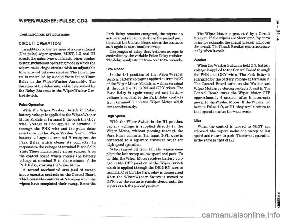
WIPERIWASHER: PULSE, CB4
(Continued from previous page)
CIRCUIT OPERATION
In addition to the features of a conventional
(Non-pulse) wiper system (MIST, LO and HI
speed), the pulse-type windshield
wiperlwasher
system includes an operating mode in which the
wipers make single strokes with an adjustable
time interval between strokes. The time inter-
val is controlled by a Solid State Pulse Timer
Relay in the WiperIWasher Assembly. The
duration of the delay interval is determined by
the Delay Rheostat
in the WiperIWasher Con-
trol Switch.
Pulse Operation
With the WiperlWasher Switch in Pulse,
battery voltage is applied to the WiperlWasher
Motor Module at terminal
B through the GRY
wire. Voltage is also applied to
terminal F
through the PNK wire and the pulse delay
resistance in the WiperlWasher Switch. The
battery voltage at terminal
B energizes the
Park Relay which closes its contacts. In
response to the voltage at terminal F, the Solid
State Timer momentarily closes contact
A on
the control board which applies the battery
voltage at terminal
B to the contacts of the
Park Relay, starting the Wiper Motor.
A second mechanical arm (end of sweep
input) operates contacts on the Control Board
which cause the contacts at A to open when the
wipers have completed their sweep. Since the Park
Relay remains energized, the wipers do
not park but remain just above the parked posi-
tion until the Control Board closes the contacts
at A again to start
another sweep.
The length of delay time between sweeps is
controlled by the variable Pulse Delay resistor.
The delay is adjustable from zero to
25 seconds.
Low Speed
In the LO position of the WiperIWasher
Switch, battery voltage is applied at terminal C
of the Wiper Motor Module as well as terminal
B, through the DK GRN and GRY wires. The
Park Relay is again energized and battery
voltage is applied to the Park Relay contacts
from terminal
G and the Wiper Motor which
runs continuously.
High Speed
With the Wiper Switch in the HI position,
battery voltage is supplied directly to the
Wiper Motor, without passing through the
Park Relay contacts. The input (PPL wire) is
connected to a separate armature brush for
high speed operation.
When turned off from HI, the wipers com-
plete the last sweep at low speed and park. To
do this, the Wiper Motor receives battery volt-
age
in the OFF position of the Wiper Switch
which is applied through the
DM GRN wire to
terminal C of
61. The Park relay is deenergized
when the WiperlWasher Switch
is moved to
OFF, but the contacts remain closed until the
wipers reach the parked position. The
Wiper Motor is protected by a Circuit
Breaker. If the wipers are obstructed, by snow
or ice for example, the circuit breaker
will open
the circuit. The Circuit Breaker resets automat-
ically when
it cools.
Washer
When the Washer Switch is held ON, battery
voltage is applied to the Control Board through
the PNK and GRY wires. The Park Relay is
energized by the battery voltage at ter
The Control Board turns on the Washer and
Wiper Motors by closing contacts A and
B. The
Control Board turns the Wiper Motor OFF
approximately
6 seconds after it interrupts
power to the Washer Motor. If the Wipers had
been in Pulse, LO, or HI, they would return to
that operation after the wash cycle.
Mist
When the control is moved to MIST and
released, the wipers make one sweep at low
speed and return to park. The circuit operation
is the same as that of LO.