jump start terminals PONTIAC FIERO 1988 Service Repair Manual
[x] Cancel search | Manufacturer: PONTIAC, Model Year: 1988, Model line: FIERO, Model: PONTIAC FIERO 1988Pages: 1825, PDF Size: 99.44 MB
Page 446 of 1825
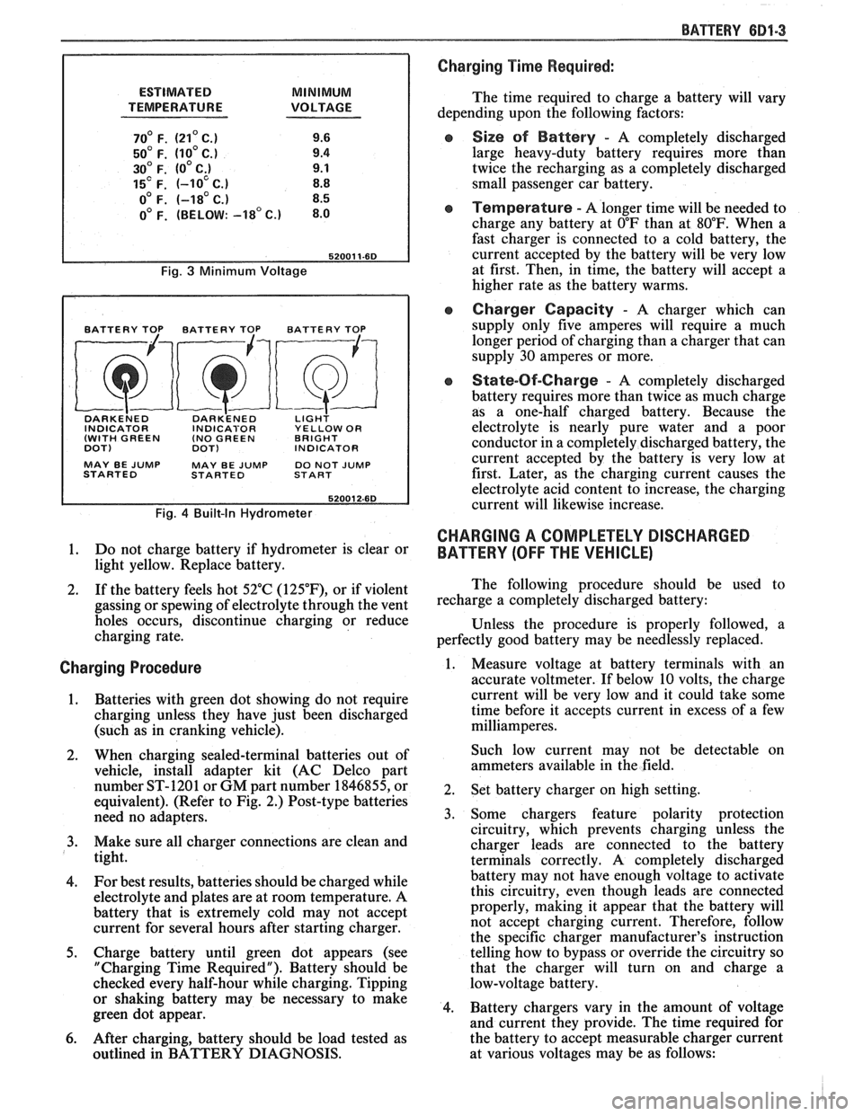
ESTIMATED MINIMUM
TEMPERATURE VOLTAGE
70' F. (21' C.) 9.6
50' F. (10' C.) 9.4
30' F. (0' C;) 9.1
15' F. (-10 C.) 8.8
o0 F. (-18' C.) 8.5
0' F. (BELOW: -18' c.) 8.0
Fig. 3 Minimum Voltage
BATTERY TOP BATTERY TOP BATTERY TOP
DARKE~ED DARK'ENED LIGH? INDICATOR INDICABOR YELLOW OR
(WITH GREEN (NO
GREEN BRIGHT
DOT)
DOT) INDICATOR
MAY BE
JUMP MAY BE JUMP DO NOT JUMP
STARTED STARTED START
Fig. 4 Built-In Hydrometer
1. Do not charge battery if hydrometer is clear or
light yellow. Replace battery.
2. If the battery feels hot 52°C
(125"F), or if violent
gassing or spewing of electrolyte through the vent
holes occurs, discontinue charging or reduce
charging rate.
Charging Procedure
1. Batteries with green
dot showing do not require
charging unless they have just been discharged
(such as in cranking vehicle).
2. When charging sealed-terminal batteries out of
vehicle, install adapter kit (AC Delco part
number ST-1201 or GM part number 1846855, or
equivalent). (Refer to Fig. 2.) Post-type batteries
need no adapters.
3. Make sure all charger connections are clean and
tight.
4. For
best results, batteries should be charged while
electrolyte and plates are at room temperature. A
battery that is extremely cold may not accept
current for several hours after starting charger.
5. Charge battery until green dot appears (see
"Charging Time Required"). Battery should be
checked every half-hour while charging. Tipping
or shaking battery may be necessary to make
green dot appear.
6. After charging, battery should be load tested as
outlined in BATTERY DIAGNOSIS.
BATTERY 681-3
Charging Time Required:
The time required to charge a battery will vary
depending upon the following factors:
e Size sf Battery - A completely discharged
large heavy-duty battery requires more than
twice the recharging as a completely discharged
small passenger car battery.
Temperature - A longer time will be needed to
charge any battery at
O"F than at 80°F. When a
fast charger is connected to a cold battery, the
current accepted by the battery will be very low
at first. Then, in time, the battery will accept a
higher rate as the battery warms.
Charger Capacity - A charger which can
supply only five amperes will require a much
longer period of charging than a charger that can
supply
30 amperes or more.
e State-Of-Charge - A completely discharged
battery requires more than twice as much charge
as a one-half charged battery. Because the
electrolyte is nearly pure water and a poor
conductor in a completely discharged battery, the
current accepted by the battery is very low at
first. Later, as the charging current causes the
electrolyte acid content to increase, the charging
current will likewise increase.
CHARGING A COMPLETELY DISCHARGED
BATTERY
(OFF THE VEHICLE)
The following procedure should be used to
recharge a completely discharged battery:
Unless the procedure is properly followed, a
perfectly good battery may be needlessly replaced.
1. Measure voltage at battery terminals with an
accurate voltmeter. If below 10 volts, the charge
current will be very low and it could take some
time before it accepts current in excess of a few
milliamperes.
Such low current may not be detectable on
ammeters available in the field.
2. Set battery charger on high setting.
3. Some chargers feature polarity protection
circuitry, which prevents charging unless the
charger leads are connected to the battery
terminals correctly. A completely discharged
battery may not have enough voltage to activate
this circuitry, even though leads are connected
properly, making it appear that the battery will
not accept charging current. Therefore, follow
the specific charger manufacturer's instruction
telling how to bypass or override the circuitry so
that the charger will turn on and charge a
low-voltage battery.
4. Battery chargers vary in the amount of voltage
and current they provide. The time required for
the battery to accept measurable charger current
at various voltages may be as follows:
Page 965 of 1825
6E-4 DRIVEABILITY AND EMISSIONS - FUEL INJECnON
and ohms. You should understand what happens in a
circuit with an open or a shorted wire. You should be
able to read and understand a wiring diagram. A
short to ground
is referred to as a ground to
distinguish it from a short between wires.
Use of Circuit Testing Tools
You should know how to use a test light, how to
connect and use
a tachometer, and how to use jumper
wires to by-pass components to test circuits. Care
should be taken to not deform the terminal when
testing.
Use of Digital Volt-Ohm Meter (DVM)
You should be familiar with the digital volt-ohm
Meter, particularly essential tool J-29125-A,
J34029A
or equivalent. You should be able to measure voltage,
resistance, and current, and know how to use the
meter correctly.
The digital volt-ohm meter is covered in the
"Special
ToolsJ'portion of this section.
DIAGNOSTIC INFORMATION
The electronic control module (ECM) is equipped
with a self-diagnosis system which detects system
failure and aids the technician by identifying the
circuit at fault via a trouble code. Below is
information about the way the ECM displays a
problem and how this corresponds to a trouble code in
the ECM. The ECM can also indicate an "Open Loop"
or "Closed Loop" mode.
"'Service Engine Soonw Light
This light is on the instrument panel, and has two
functions:
@ It is used to tell the driver that a problem has
occurred, and that the vehicle should be taken for
service as soon as reasonably possible.
@ It is used by the technician to read out "Trouble
CodesJ' to help diagnose system problems.
As a bulb and system check, the light will come
"ON" with the key "ON" and the engine not running.
When the engine is started, the light will turn "OFF".
If the light remains "ONJ', the self-diagnostic system
has detected a problem. If the problem goes away, the
light will go out in most cases after 10 seconds, but a
Trouble Code will remain stored in the ECM.
Intermittent "Service Engine Soon" Light
The diagnostic charts in Section "A" are set up to
check whether or not a stored trouble code is
"intermittent" or "hard". An
"intermittent" code is one which does not
always reset when the code setting parameters are
met, or is not present while you are working on the
vehicle. This is often caused by
a loose connection.
The facing page will contain diagnostic aids to help in
detecting
intermittents.
A "hard" code is one which is present when you
are working on the vehicle and the condition still
exists while working on the vehicle. The chart with
the stored trouble code number will lead you to the
cause of the problem.
Trouble Codes
The engine control module (ECM) is really a
computer. It uses sensors to look at many engine
operating conditions. It has
a memory and it knows
what certain sensor readings should be under certain
conditions. These conditions are described on the
facing page of each Trouble Code chart. If a sensor
reading is not what the ECM thinks it should be, the
ECM will turn "ON" the "Service Engine Soon" light
on the instrument panel, and will store a Trouble Code
in the memory. The Trouble Code tells which circuit
the trouble is in. A circuit consists of a sensor (such as
coolant temperature), the wiring and connectors to it,
and the ECM.
i
To get a Trouble Code out of the ECM, we use the
assembly line diagnostic link (ALDL) connector.
!
ALDL Connector I
I
The assembly line diagnostic link (ALDL) is a
diagnostic connector located in the passenger
compartment (Figure 2). It has terminals which are
used in the assembly plant to check that the engine is
operating properly before it leaves the plant.
Terminal "B" is the Diagnostic terminal, and it can be
connected to terminal
"A", or ground, to enter the
Diagnostic mode, or the Field Service Mode.
The ALDL connector is also used by "ScanJ' tools to
read information from the ECM via the Serial Data
Line. Serial Data information
is used extensively
throughout the manual.
Diagnostic Mode
1
If the Diagnostic terminal is grounded with the
ignition "ON" and the engine stopped, the system will
enter the Diagnostic Mode. In this mode the ECM
will:
1. Display a Code 12 by flashing the "Service Engine
Soon" light (indicating the system is operating). A
Code 12 consists of one flash, followed by a short
pause, then two flashes in quick succession. This
code will be flashed three times. If no other codes
Page 1186 of 1825
TROUBLESHOOTING TESTS m r rn 0
With a Short Finder
1. Remove the blown fuse, leaving the Battery
connected.
2. Connect the Short Finder across the fuse
terminals.
3. Close all switches in series with the circuit
you are troubleshooting.
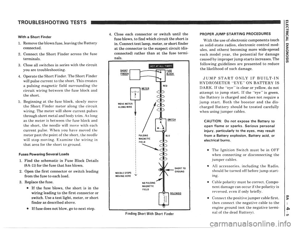
4. Operate the Short Finder. The Short Finder
will pulse current to the short. This creates
a pulsing magnetic field surrounding the
circuit wiring between the fuse block and
the short.
5. Beginning at the fuse block. slowly move
the Short Finder meter along the circuit
wiring. The meter will show current pulses
through sheet
inetal and body trim. As long
as the meter is between the fuse block and
the short, the needle will move with each
current pulse. When you have
moved the
meter past the point of the short. the needle
will stop
moving. Examine the wiring in
that area for the short to ground.
Fuses Powering Several Loads
1. Find the schematic in Fuse Block Details
(8A-11) for the fuse that has blown.
2. Open the first connector or switch leading
from the fuse to each load.
3. Replace the fuse.
@ If the fuse blows, the short is in the
wiring leading to the first connector or
switch. Use a test light, meter, or short
finder as described above.
@ If fuse does not blow, go to next step.
4. Close each connector or switch until the PROPER JUMP STARTING PROCEDURES
fuse blows, to find which circuit the short is
With the use of electronic components (such
in. Connect test lamp, meter, or short finder
as solid-state radios, electronic control
mod- at the connector to the suspect circuit (dis- ules, and others) becoming more wide-spread
connected) rather than at the fuse termi- each model year, the potential for damage nals. caused by improper jump starts increases. The
SHORT FUSE FINDER - BLOCK -
MOVE METER
NEEDLE STOPS
MOVING HERE
NO PULSING
MAGNETIC
FIELD
Cb
SHORT TO
GROUND
w-
Finding Short With Short Finder
following guidelines are presented to reduce
the likelihood of such damage.
JUMP START ONLY IF BUILT-IN
HYDROMETER "EYE" ON BATTERY IS
DARK. If the "eye" is clear or yellow, do not
attempt to jump start. If the "eye" is green,
the Battery is charged and does not require a
jump start. Both the booster and the dis-
charged Battery should be treated carefully
when using jumper cables.
CAUTION: Do not expose the Battery to
open flame or sparks. Serious personal
injury, particularly
to the eyes, may result
from
a Battery explosion, Battery acid, or
electrical burns.
The Ignition Switch must be in OFF
when connecting or disconnecting the
jumper cables.
All accessories. including the Radio.
should be turned off before jump start-
ing.
Cable polarity must be correct. Compo-
nent damage can occur
if the polarity is
re~~ersed. even if only briefly.
a Connect the positive jumper cable first.
then connect the negative cable to the
engine ground (not the negative termi-
nal of the dead Battery).
Page 1298 of 1825
STARTER AND CHARGING SYSTEM
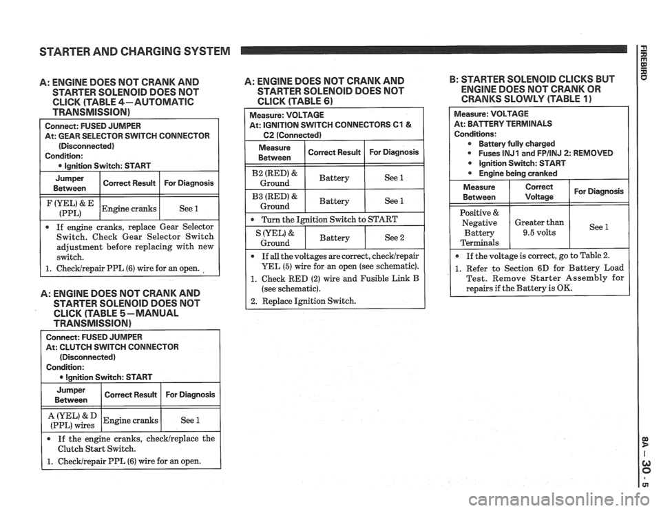
A: ENGINE DOES NOT CRANK AND
STARTER SOLENOID DOES NOT
CLICK (TABLE 4-AUTOMATIC
TRANSMISSION)
Connect: FUSED JUMPER
At: GEAR SELECTOR SWITCH CONNECTOR
(Disconnected)
Condition:
0 Ignition Switch: START
I
Jumper I Corren Resuk I For Diagnosis I Between
I (:::LI& IEngine cranks I See 1 1
If engine cranks, replace Gear Selector
Switch. Check Gear Selector Switch
adjustment before replacing with new
switch.
1. ChecWrepair PPL (6) wire for an open.
A: ENGINE DOES NOT CRANK AND
STARTER SOLENOlD DOES NOT
CLICK (TABLE 5-MANUAL
TRANSMISSION)
Connect: FUSED JUMPER
At: CLUTCH SWITCH CONNECTOR
(Disconnected)
Condition:
I 0 lanition Switch: START I
I :if,",":: 1 Engine cranks I See 1 I
Jumper
Between
If the engine cranks, checklreplace the
Clutch Start Switch.
1. Checklrepair PPL (6) wire for an open.
A: ENGINE DOES NOT CRANK AND B:
STARTER SOLENOID CLICKS BUT
STARTER
SOLENOID DOES NOT ENGINE DOES NOT CRANK OR
CLICK (TABLE 61 CRANKS SLOWLY (TABLE 1)
Correct Result Measure:
VOLTAGE
At: IGNITION SWITCH CONNECTORS
C1 &
C2 (Connected)
For Diagnosis
I Measure ( Correct Result I For Diagnosis 1 Between
I B2 (RED)& I Battery ( See 1 I Ground
I B3 IRED'& I Battery ( See 1 1 Ground
0 Turn the Ignition Switch to START
Measure: VOLTAGE
At: BPirTERV TERMINALS
Conditions: Battery fully charged
0 Fuses lNJ1 and FPIINJ 2: REMOVED
Ignition Switch: START
Engine being cranked
See 2 IYEL' &
Ground
For Diagnosis
See
Measure
Between
Positive &
Negative Battery
Terminals
If
all the voltages are correct, checklrepair
YEL (5) wire for an open (see schematic).
1. Check RED (2) wire and Fusible Link B
(see schematic).
2. Replace Ignition Switch.
Battery
0 If
the voltage is correct, go to Table 2.
1. Refer to Section 6D for Battery Load
Test. Remove Starter Assembly for
repairs if the Battery is
OK.
Correct
Voltage
Greater than
9.5 volts
Page 1515 of 1825
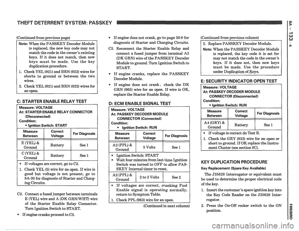
Continued from previous page)
Note: VVhen the PASSKEY Decoder Module
is replaced, the new key code may not
match the code in the owner's existing
keys. If it does not match, then new
keys must be made. Use the key
duplication procedure.
1. Check YEL (921) and BRN (922) wires for
shorts to ground or between the two
wires.
2. Check
UEL (921) and BRN (922) wires for
an open. If
engine does not crank, go to page 30-0 for
diagnosis of Starter and Charging Circuits.
C3. Reconnect the Starter Enable Relay and
connect a fused jumper from terminal A3
(DK GRN) wire of the PASSKEY Decoder
Module to ground. Ignition Switch to
START.
0 If engine cranks, replace the PASSKEY
Decoder Module.
If engine does not crank, check the DK
GRN (965) wire for
an open. If wire is OK,
replace the Starter Enable Relay.
6: STARTER ENABLE RELAY TEST
D: ECM ENABLE SIGNAL TEST
C2. Connect a fused jumper between terminals
Measure: VOLTAGE
At: STARTER ENABLE RELAY CONNECTOR
(Disconnected)
Condition:
0 Ignition Switch: START Measure:
VOLTAGE
At: PASSKEY DECODER MODULE
CONNECTOR (Connected)
Condition: 0 Ignition Switch: RUN
Measure
Between
&
Ground
&
Ground
Measure
Between I I For Diagnosis ( Voltage
1 I 5Volts I See 1 1
If voltages are correct, go to C2.
1. Check YEL (5) wire for an open. If wire is
good but voltage is not present, go to
8A-30 for diagnosis of Starter and Charg-
ing Circuits.
Correct
Voltage
Battery
Battery
I I
Ignition Switch: START
For Diagnosis
See 1
See 1
0 wait four minutes from last time Ignition
Switch was turned to OFF to
allow PAS-
SKEY Internal timer to reset.
I A2 IPPL)& ) 2 to3Volts I See2 i Ground
If voltages are correct, cranking Fuel
Enable signal is operating normally,
return to Symptom Table.
E (YEL) Vfire and A (DK GR wire 1 1. Check PPL (963) wire for an open. A of the Starter Enable Relay Connector. I I
(Continued in next column)
Ignition Switch to START.
If engine cranks proceed to
63.
Continued from previous column)
2. Replace PASSKEY Decoder Module.
Note: When the PASSKEY Decoder Module
is replaced, the key code
it is set for
may not match the code in the owner's
keys. If
it does not, then new keys
must be made. Use the procedure
under
Duplicgti~n of-Keys2
E: SECURITY INDICATOR OPEN TEST
CONNECTOR (Disconnected)
Condition:
KEY DUPLICATION PROCEDURE
Key Replacement (Spare Key Available)
The 535628 Interrogator or equivalent must
be used to det e
the proper electrical code
of the key.
1. Insert the customer's spare ignition key into
the Key Code Reader on the 535628 Inter-
rogator.
2. Press the On-Off rocker switch to the ON
position.