wheel bolts PONTIAC FIERO 1988 Service Repair Manual
[x] Cancel search | Manufacturer: PONTIAC, Model Year: 1988, Model line: FIERO, Model: PONTIAC FIERO 1988Pages: 1825, PDF Size: 99.44 MB
Page 18 of 1825
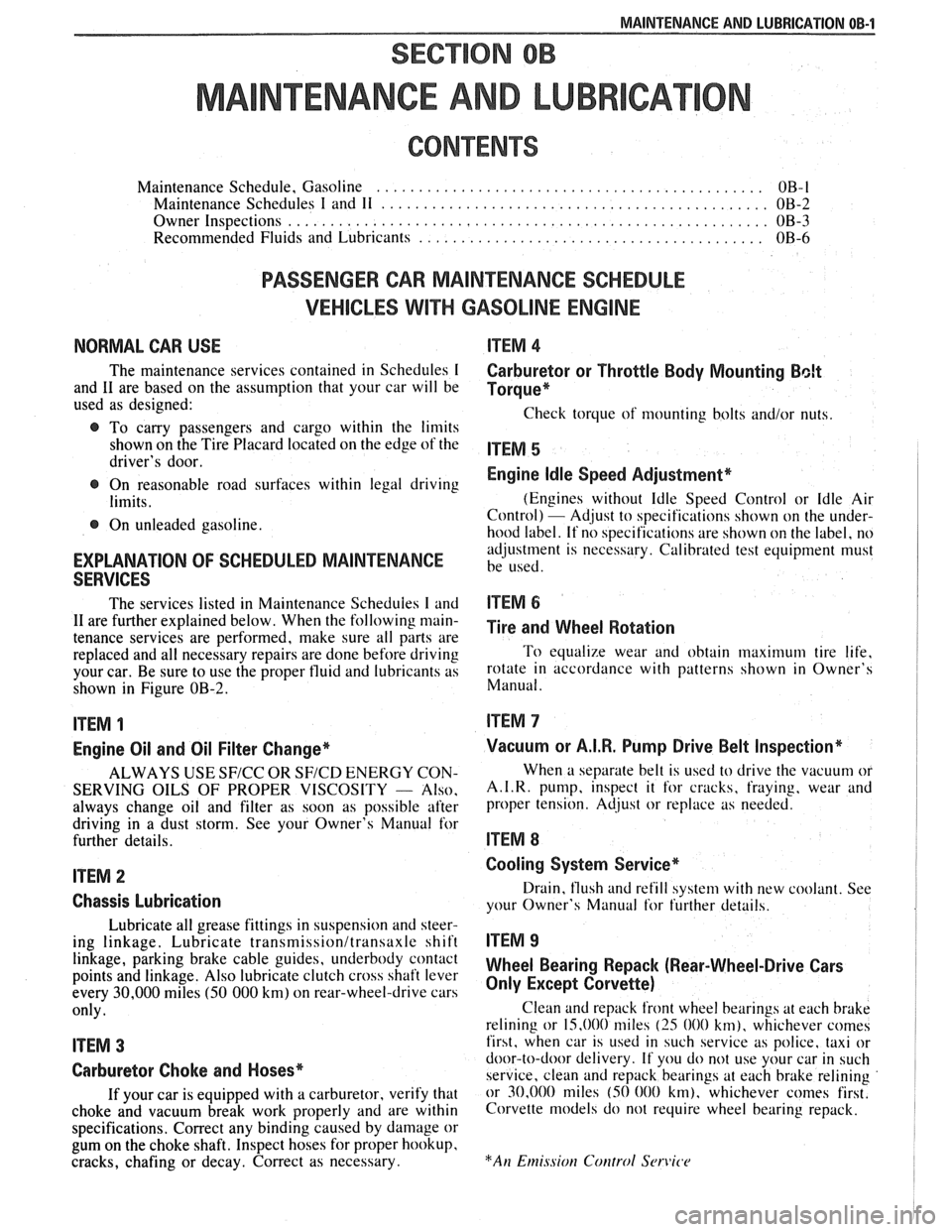
MAINTENANCE AND LUBRICATION OB-1
SECTION OB
NTENANCE AND LUBR
CONTENTS
Maintenance Schedule, Gasoline .............................................. OB-l
Maintenance Schedules I and 11 .............................................. OB-2
Owner Inspections
......................................................... OB-3
Recommended Fluids and Lubricants ......................................... OB-6
PASSENGER CAR MAINTENANCE SCHEDULE
VEHICLES
WITH GASOLINE ENGINE
NORMAL CAR USE ITEM 4
The maintenance services contained in Schedules I Carburetor or Throttle Body Mounting Bolt
and 11 are based on the assumption that your car will be Torque* used as designed:
Check torque of mounting bolts and/or nuts. @ To carry passengers and cargo within the limits
shown on the Tire Placard located on the edge of the ITEM 5 driver's door.
@ On reasonable road surfaces within legal driving Engine Idle Speed Adjustment*
limits. (Engines
without Idle Speed Control or Idle Air
Control) - Adjust to specifications shown on the under- @ On unleaded gasoline.
hood label. If no specifications are shown on the label, no
adjustment is necessary. Calibrated test equipment must
EXPLANATION OF SCHEDULED MAINTENANCE be used. SERVICES
The services listed in Maintenance Scheduies I and ITEM 6
11 are further explained below. When the following main- ~i~~ and wheel aotation tenance services are performed, make sure all parts are
replaced and all necessary repairs are done before driving To equalize wear and obtain maximum tire life,
your car. Be sure to use the proper fluid and lubricants as rotate in accordance with patterns shown in Owner's
shown in Figure OB-2. Manual.
ITEM 1
Engine Oil and Oil Filter Change*
ALWAYS USE SFICC OR SF/CD ENERGY CON-
SERVING OILS OF PROPER VISCOSITY
- Also.
always change oil and filter as soon as possible after
driving in a dust storm. See your Owner's Manual for
further details.
ITEM 2
Chassis Lubrication
Lubricate all grease fittings in suspension and steer-
ing linkage. Lubricate
transmissionltransaxle shift
linkage, parking brake cable guides, underbody contact
points and linkage. Also lubricate clutch cross shaft lever
every
30,000 miles (50 000 km) on rear-wheel-drive cars
only.
ITEM 3
Carburetor Choke and Hoses*
If your car is equipped with a carburetor, verify that
choke and vacuum break work properly and are within
specifications. Correct any binding caused by damage or
gum on the choke shaft. Inspect hoses for proper hookup,
cracks, chafing or decay. Correct as necessary.
Vacuum or A.I.R. Pump Drive Belt Inspection*
When a separate belt is used to drive the vacuum or
A.I.R.
pump, inspect it for cracks, fraying, wear and
proper tension. Adjust or replace as needed.
ITEM 8
Cooling System Service*
Drain, flush and refill system with new coolant. See
your Owner's Manual
for further details.
ITEM 9
Wheel Bearing Repack (Rear-Wheel-Drive Cars
Only Except Corvette)
Clean and repack front wheel bearings at each brake
relining or 15,000 miles
(25 000 km), whichever comes
first, when car is used in such service as police, taxi or
door-to-door delivery. If you do not use your car in such
service, clean and repack bearings at each brake relining
or 30,000 miles
(50 000 km), whichever comes first.
Corvette models do not require wheel bearing repack.
Page 117 of 1825

2C-10 CHASSIS SHEET METAL
ROCKER PANEL AIR DEFLECTOR
Remove or Disconnect
1. Five top screws (#I).
2. Hoist car.
3. Seven bolts holding rocker panel rubber
air
deflector
(#2) and remove.
4. Seven screws holding rocker deflector to bottom
of rocker panel
(#3).
5. Two screws holding rear rocker deflector to rear
wheel opening
(#4).
6. Five
push type fasteners at the lower rear of the
wheel well splash shield, lift shield to gain
access to the two forward nuts.
7. Two nuts (#5) from rocker deflector front to
fender.
8. Rocker deflector.
9. Nine screws holding rocker panel deflector
support.
10. Support.
Install or Connect
To install, reverse removal procedure.
REAR BUMPER FASCIA EXTENSION
Remove or Disconnect
1. Hoist car,
2. Drill out
eight fascia extension to fascia rivets
(#I) (four each side). Four
bolts from fascia extension to lower quar-
ter panel
(#2).
Five (each side) push clips from fascia to sup-
port
(443).
Four screws from rear fascia extension to fender
(#4).
Lower car.
Right side trunk trim and spare tire.
Rear trim panel.
Left trim panel.
Right and left side fascia and fascia extension
nuts (six each side)
(#5).
Right and left tail lamp wing nuts and remove
housing.
Seven fascia push nuts and disconnect electrical
connector for license plate
(#6).
Rear bumper fascia from car.
Twelve (six each side) fascia extension to fascia
retaining nuts and remove fascia extension
(#7).
Install or Connect
To install, reverse removal procedure.
Page 127 of 1825
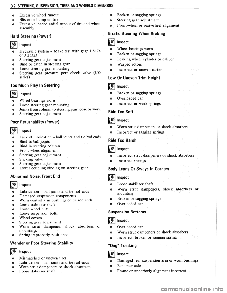
3-2 STEERING, SUSPENSION, TIRES AND WHEELS DIAGNOSIS
o Excessive wheel runout
e Blister or bump on tire
e Excessive loaded radial runout of tire and wheel
assembly
Hard Steering (Power)
lnspect
e Hydraulic system - Make test with gage J 5176
or J 25323
e Steering gear adjustment
e Bind or catch in steering gear
e Loose steering gear mounting
e Steering gear pressure port check valve (800
series)
Too Much Play In Steering
a lnspect
e Wheel bearings worn
e Loose steering gear mounting
e Joints from column to steering gear loose or worn
e Steering gear adjustment
Poor Returnability (Power)
Inspect
e Lack of lubrication - ball joints and tie rod ends
o Bind in ball joints
o Rind in steering column
e Front-wheel alignment
e Steering gear adjustment
e Sticking valve
o Steering gear adjustment
e Lower coupling binding on steering gear
Abnormal Noise, Front End
lnspect
Lubrication - ball joints and tie rod ends
Damaged suspension components
Worn control arm bushings or tie rod ends
Imose stabilizer shaft
Loose wheel nuts
Loose suspension bolts
Wheel covers
Steering gear adjustment
Worn strut dampener, shock absorbers or
n~ountings
Spring improperly positioned
Wander or Poor Steering Stability
Inspect
o Mismatched or uneven tires
e Lubrication - ball joints and tie rod ends
e Worn strut dampeners or shock absorbers
e Loose stabilizer shaft Broken
or sagging springs
e Steering gear adjustment
e Front-wheel or rear-wheel alignment
Erratic Steering When Braking
lnspect
e Wheel bearings worn
e Broken or sagging springs
e Leaking wheel cylinder or caliper
Warped rotors
e Incorrect or uneven caster
Low Or Uneven Trim Height
e Broken or sagging springs
@ Overloaded car
e Incorrect or weak springs
Ride Too Soft
Inspect
e Worn strut dampeners or shock absorbers
e Incorrect or sagging springs
Ride Too Harsh
lnspect -
e Incorrect strut dampeners or shock absorbers
e Incorrect springs
Body Leans Or Sways In Corners
lnspect
e Loose stabilizer shaft
e Worn strut dampeners, shock absorbers or
mounting
a Broken or sagging springs
e Overloaded car
Suspension Bottoms
lnspect
a Overloaded car
e Worn strut dampeners or shock absorbers
e Incorrect, broken or sagging spring
"Dog" Tracking
lnspect
e Damaged rear suspension arm or worn bushings
e Bent rear axle
e Frame or underbody alignment incorrect
Page 130 of 1825
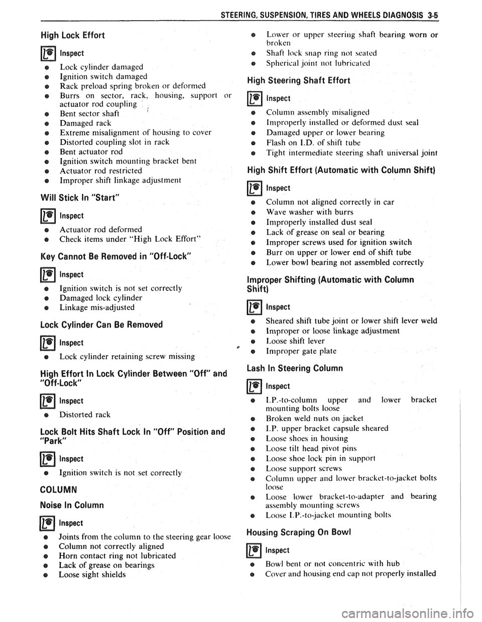
STEERING. SUSPENSION. TIRES AND WHEELS DIAGNOSIS 3-5
High Lock Effort
rn lnspect
e Lock cylinder damaged
e Ignition switch damaged
o Rack preload spring broken or deformed
e Burrs on sector, rack, housing, support or
actuator rod coupling
,
e Bent sector shaft
e Damaged rack
e Extreme misalignment of' housing to cover
e Distorted coupling slot in rack
e Bent actuator rod
e Ignition switch mounting bracket bent
e Actuator rod restricted
e Improper shift linkage adjustment
Will Stick In "Start"
rn lnspect
e Actuator rod deformed
e Check items under "High Lock Effort"
Key Cannot Be Removed in "Off-Lock"
rn lnspect
e Ignition switch is not set correctly
e Damaged lock cylinder
e Linkage mis-adjusted
Lock Cylinder Can Be Removed
Inspect
e Lock cylinder retaining screw missing
High Effort In Lock Cylinder Between "Off" and
"Off-Lock"
lnspect
o Distorted rack
Lock Bolt Hits Shaft Lock In "Off" Position and
"Park"
lnspect
e Ignition switch is not set correctly
COLUMN
Noise In Column
Inspect
e Joints from the column to the steering gear 1
e Column not correctly aligned
e Horn contact ring not lubricated
e Lack of grease on bearings
o Loose sight shields
o Lower or upper steering shaft bearing worn or
broken
e Shaft lock snap ring not seated
o Spherical joint not lubricated
High Steering Shaft Effort
e Column assembly misaligned
e Improperly installed or deformed dust seal
e Damaged upper or lower bearing
e Flash on I.D. of shift tube
e Tight intermediate steering shaft universal joint
High Shift Effort (Automatic with Column Shift)
rn lnspect
e Column not aligned correctly in car
e Wave washer with burrs
e Improperly installed dust seal
o Lack of grease on seal or bearing
e Improper screws used for ignition switch
e Burr on upper or lower end of shift tube
e Lower bowl bearing not assembled correctly
Improper Shifting (Automatic with Column
Shift)
rn lnspect
e Sheared shift tube joint or lower shift lever weld
e Improper or loose linkage adjustment
e 1,oose shift lever
e Improper gate plate
Lash In Steering Column
lnspect
e 1.P.-to-column upper and lower bracket
nlounting bolts loose
e Broken weld nuts on jacket
e I.P. upper bracket capsule sheared
e Loose shoes in housing
e Loose tilt head pivot pins
e Loose shoe lock pin in support
e Loose support screws
e Column upper and lower bracket-to-jacket bolts
loose
e Loose lower bracket-to-adapter and bearing
assembly mounting screws
e Loose 1.P.-to-jacket mounting bolts
Housing Scraping On Bowl
rn Inspect
e Bowl bent or not concentric with hub
e Cover and housing end cap not properly installed
Page 149 of 1825
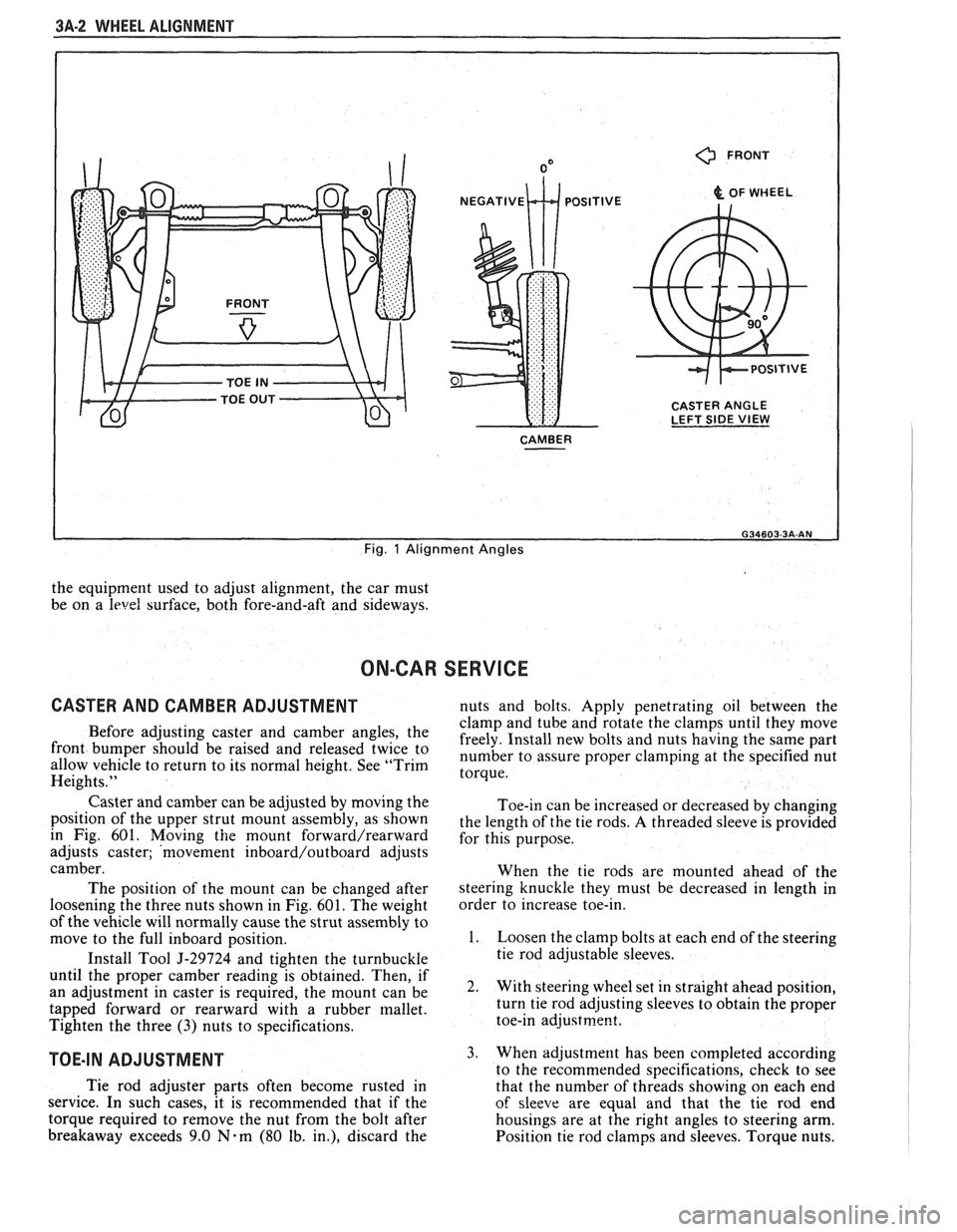
3A-2 WHEEL ALIGNMENT
0 FRONT
& OF WHEEL
CASTER ANGLE
LEFT SIDE
VIEW
CAMBER
I
Fig. 1 Alignment Angles
the equipment used to adjust alignment, the car must
be on a
level surface, both fore-and-aft and sideways.
ON-CAR SERVICE
CASTER AND CAMBER ADJUSTMENT nuts and bolts. Apply penetrating oil between the
clamp and tube and rotate the clamps until they move
Before adjusting caster and camber the freely. Install new bolts and nuts having the same part front be 'aised and twice to number to assure proper at the specified nut allow vehicle to return to its normal height. See "Trim torque. Heights."
Caster and camber can be adjusted by moving the
position of the upper strut mount assembly, as shown
in Fig. 601. Moving
the mount forward/rearward
adjusts caster; 'movement inboard/outboard adjusts
camber.
The position of the mount can be changed after
loosening the three nuts shown in Fig.
601. The weight
of the vehicle will normally cause the strut assembly to
move to the full inboard position.
Install Tool
5-29724 and tighten the turnbuckle
until the proper camber reading is obtained. Then, if
an adjustment in caster is required, the mount can be
tapped forward or rearward with a rubber mallet.
Tighten the three
(3) nuts to specifications.
TOE-IN ADJUSTMENT
Toe-in can be increased or decreased by changing
the length of the tie rods.
A threaded sleeve is provided
for this purpose.
When the tie rods are mounted ahead of the
steering knuckle they must be decreased in length in
order to increase toe-in.
1. Loosen the clamp bolts at each end of the steering
tie rod adjustable sleeves.
2. With steering wheel set in straight ahead position,
turn tie rod adjusting sleeves to obtain the proper
toe-in
adjustrne~t.
3. When adjustment has been completed according
to the recommended snecifications. check to see
Tie rod adjuster parts often become rusted in
that the number of thrkads showing on each end
service. In such cases, it is recommended that if the
of sleeve are equal and that the tie rod end
torque required to remove the nut from the bolt after housings are at the right angles to steering arm.
breakaway exceeds 9.0
Nam (80 lb. in.), discard the
Position tie rod clamps and sleeves. Torque nuts.
Page 152 of 1825
STEERING WHEELS AND COLUMNS 385.1
SECTION 3B5
STEER NG WHEELS AND COLUMNS
NOTICE: All steering wheel and column fasteners are important attaching parts in that they could affect
the performance of vital parts and systems, and/or could result in major repair expense. They
must be replaced
with one of the same part number or with an equivalent part if
replacement becomes necessary. Do not use a
replacement part of lesser quality or substitute design. 'Torque values must be used as specified during reassembly
to assure proper retention of all parts. There is to be no welding as
it may result in extensive damage and weakening
of the metal.
For prevailing torque
nut(s) and bolts(s), refer to the "Reuse of Prevailing Torque Nut(<) and Bolt(s) " chart
in Section OA.
CONTENTS
..................... ................................................................... GENERAL DESCRIPTION .. 3B5-1 ............................................. ........................ MAINTENANCE AND ADJUSTMENTS .. 3B5-1 ON-CAR SERVICE ........................................................................................................ 3B5-2
Steering Column ............................................................................................................ 3B5-2 ......................................................................................................... Intermediateshaft 3B5-3
Park Lock Cable .................................................................... 3B54 ......................................................................................... Checking For Accident Damage 3B5-5 ............................................................................ Unit Repair Intermediate Shaft Assembly 3B5-6
..................................................................................... Standard Column @lanual Trans) 3B5-7 ......................................................... ....................... Standard Column (Auto Trans) .. 3B5-13 Tilt Column (Manual Trans) ............................................................................................. 3B5-19
Tilt Column (Auto Trans). ................................................................................................ 3B5-27
................ .................... TORQUE SPECIFICATIONS .. .. 3B5-35
SPECIAL TOOLS .......................................................................................................... 3B5-35
GENERAL DESCRIPTION
STEERING COLUMN
The function locking energy absorbing steering
column includes three important features in addition
to the steering function:
1. 'The column is energy absorbing, designed to
compress in a front-end collision to minimize the
possibility of an injury to the driver of the car.
2. The ignition switch and lock are mounted
conveniently on this column.
3. With the column mounted lock, the ignition and
steering operations can be locked to inhibit theft
of the car.
The turn signal lever provides for control of
headlight beams, windshield washer and wipers.
The column may be easily
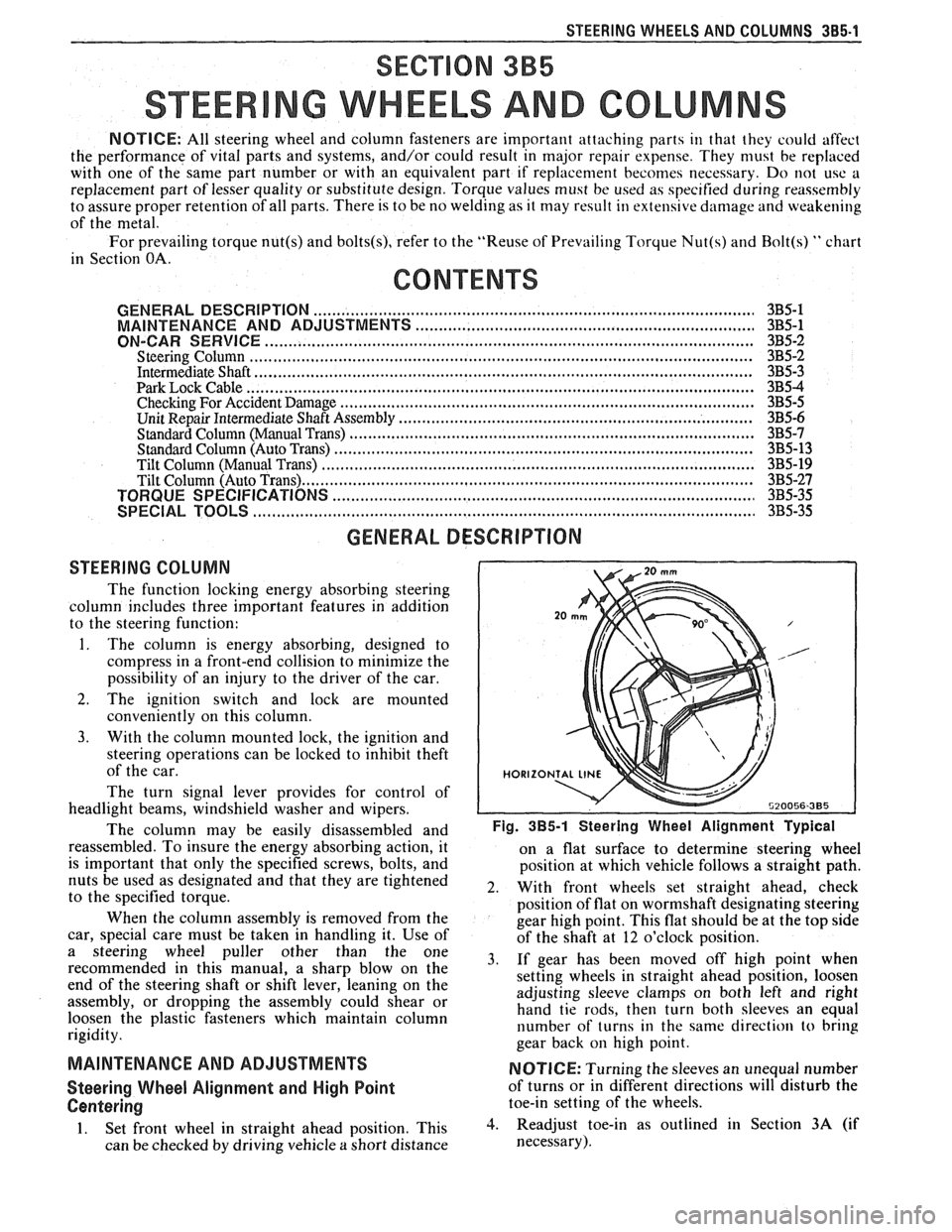
disassembled and Fig. 385-1 Steering Wheel Alignment ~ypical
reassembled. To insure the energy absorbing action, it
on a flat surface to determine steering wheel
is important that only the specified screws, bolts, and
position at which vehicle follows a straight path.
nuts be used as designated and that they are tightened
2. With front wheels set straight ahead, check to the specified torque.
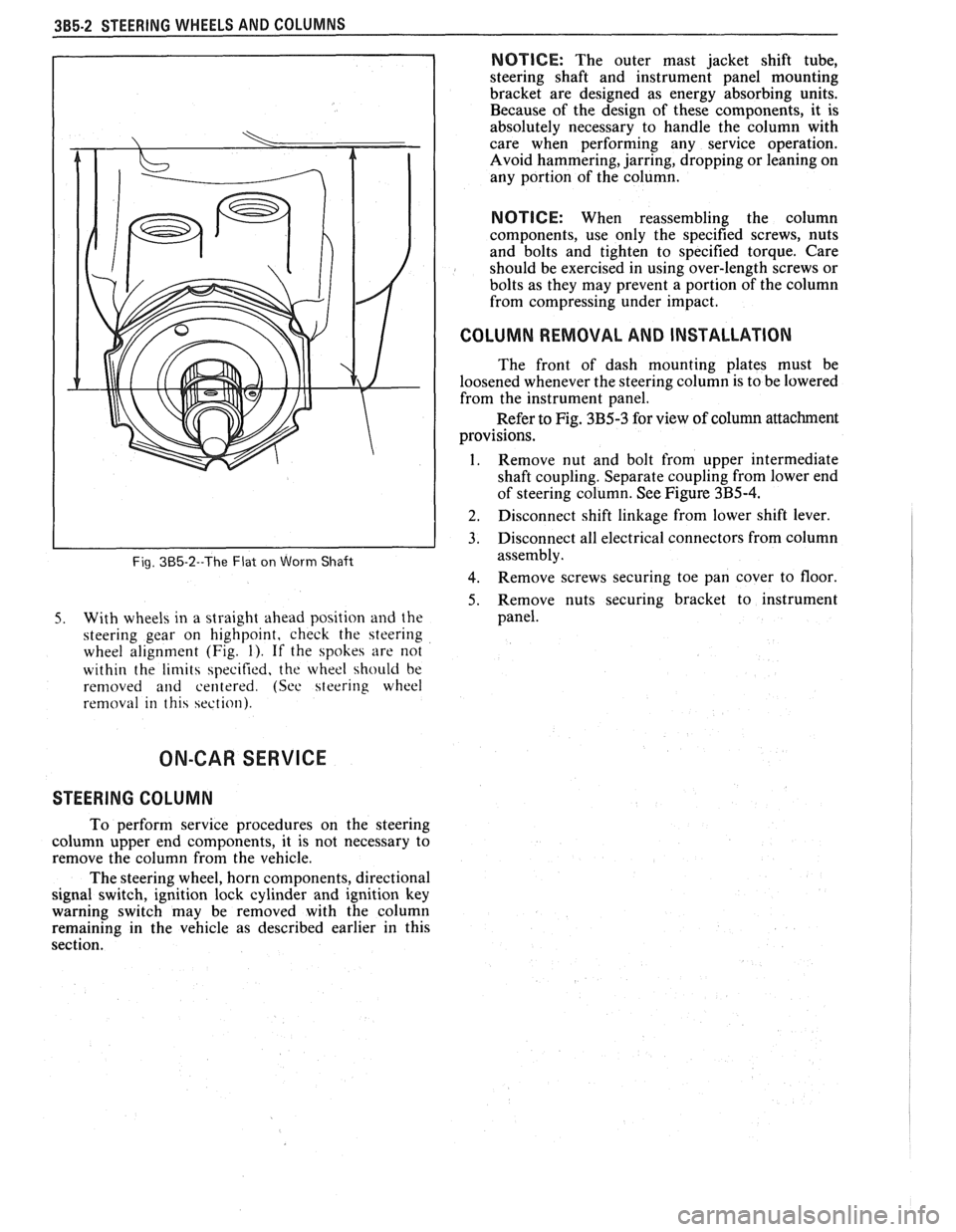
position of flat on wormshaft designating steering
When the column assembly is removed from the
gear high point. This flat should be at the top side
car, special care must be taken in handling it. Use of
of the shaft at 12 o'clock position.
a steering puller other than the One 3, if gear has been moved off high when recommended in this manual, a sharp blow on the
setting wheels in straight ahead position, loosen
end of the steering shaft or shift lever, leaning on the
assembly, or dropping the assembly could shear or adjusting
sleeve clamps on both left and right
hand tie rods, then turn both sleeves an equal
loosen the plastic fasteners which maintain column
rigidity. number
of turns in the same direction
to bring
gear back
on high point.
MAINTENANCE AND ADJUSTMENTS NOTICE: Turning the sleeves an unequal number
Steering Wheel Alignment and High Point of turns or in different directions will disturb the
Centering toe-in setting of the wheels.
1. Set front wheel in straight ahead position, This 3. Readjust toe-in as outlined in Section 3A (if
can be checked by driving vehicle
a short distance necessary).
Page 153 of 1825
385-2 STEERING WHEELS AND COLUMNS
Fig. 385-2--The Flat on Worm Shaft
5. With wheels in a straight ahead position and the
steering gear on highpoint, check the steering
wheel alignment (Fig.
1). If the spokes are not
within the
limits specified, the wheel should be
removed
and centered. (See steering wheel
removal in this section).
NOTICE: The outer mast jacket shift tube,
steering shaft and instrument panel mounting
bracket are designed as energy absorbing units.
Because of the design of these components, it is
absolutely necessary to handle the column with
care when performing any service operation.
Avoid hammering, jarring, dropping or leaning on
any portion of the column.
NOTICE: When reassembling the column
components, use only the specified screws, nuts
and bolts and tighten to specified torque. Care
should be exercised in using over-length screws or
bolts as they may prevent a portion of the column
from compressing under impact.
I COLUMN REMOVAL AND INSTALLATION
The front of dash mounting plates must be
loosened whenever the steering column is to be lowered
from the instrument panel.
Refer to Fig. 3B5-3 for view of column attachment
provisions.
1. Remove nut and bolt from upper intermediate
shaft coupling. Separate coupling from lower end
of steering column. See Figure
3B5-4.
] 2. Disconnect shift linkage from lower shift lever.
3. Disconnect all electrical connectors from column
assembly.
4. Remove screws securing toe pan cover to floor
5. Remove nuts securing bracket to instrument
panel.
ON-CAR SERVICE
STEERING COLUMN
To perform service procedures on the steering
column upper end components, it is not necessary to
remove the column from the vehicle.
The steering wheel, horn components, directional
signal switch, ignition lock cylinder and ignition key
warning switch may be removed with the column
remaining in the vehicle as described earlier in this
section.
Page 169 of 1825
385-18 STEERING WHEELS AND COLUMNS
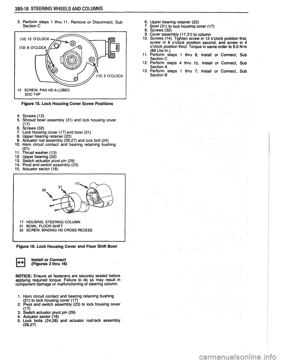
(12) 12 O'CLOCK
3. Perform steps 1 thru 11, Remove or Disconnect, Sub 6. Upper bearing retainer (22)
Section C 7. Bowl (31) to lock housing cover (17)
8. Screws (32)
9. Cover assembly (1
7,31) to column
10. Screws (14). Tighten screw in 12 o'clock position first,
screw in 8 o'clock position second, and screw in 4
o'clock position third. Torque in same order to 9.0
N.m (89 Lbs.ln.) 11. Perform steps 1 thru 8, Install or Connect, Sub
Section C 12. Perform steps 4 thru 15, Install or Connect, Sub
Section A
13. Perform steps 1 thru 7, Install or Connect, Sub
Section
B
Figure 15. Lock Housing Cover Screw Positions
4. Screws (12)
5. Shroud bowl assembly
(31) and lock housing cover 1171 6. ~c:dr'ews (32)
7. Lock housing cover (1 7) and bowl (31)
8. Upper bearing retainer (22)
9. Actuator rod assembly (26,27) and lock bolt (24)
10. Horn circuit contact and bearing retaining bushing
121 1 11. Yhiust washer (1 3) 12. Upper bearing (20)
13. Switch actuator pivot pin (29)
14. Pivot and switch assembly (23)
15. Actuator sector (1 8)
17. HOUSING, STEERING COLUMN 31. BOWL, FLOOR SHIFT 32. SCREW, BINDING HD CROSS RECESS
Figure 16. Lock Housing Cover and Floor Shin Bowl
Install
or Connect (Figures 2 thru 16)
NOTICE: Ensure all fasteners are securely seated before
applying required torque. Failure to do so may result in
component damage or malfunctioning of steering column.
1. Horn circuit contact and bearing retaining bushing
(21 ) to lock housing cover (1 7)
2. Pivot and switch assembly (23) to lock housing cover
(1 7) 3. Switch actuator pi~ot pin (29)
4. Actuator sector (1 8) 5. Lock bolts (2428) and actuator rodlrack assembly (26,271
Page 192 of 1825
STEERING LINKAGE 386-5
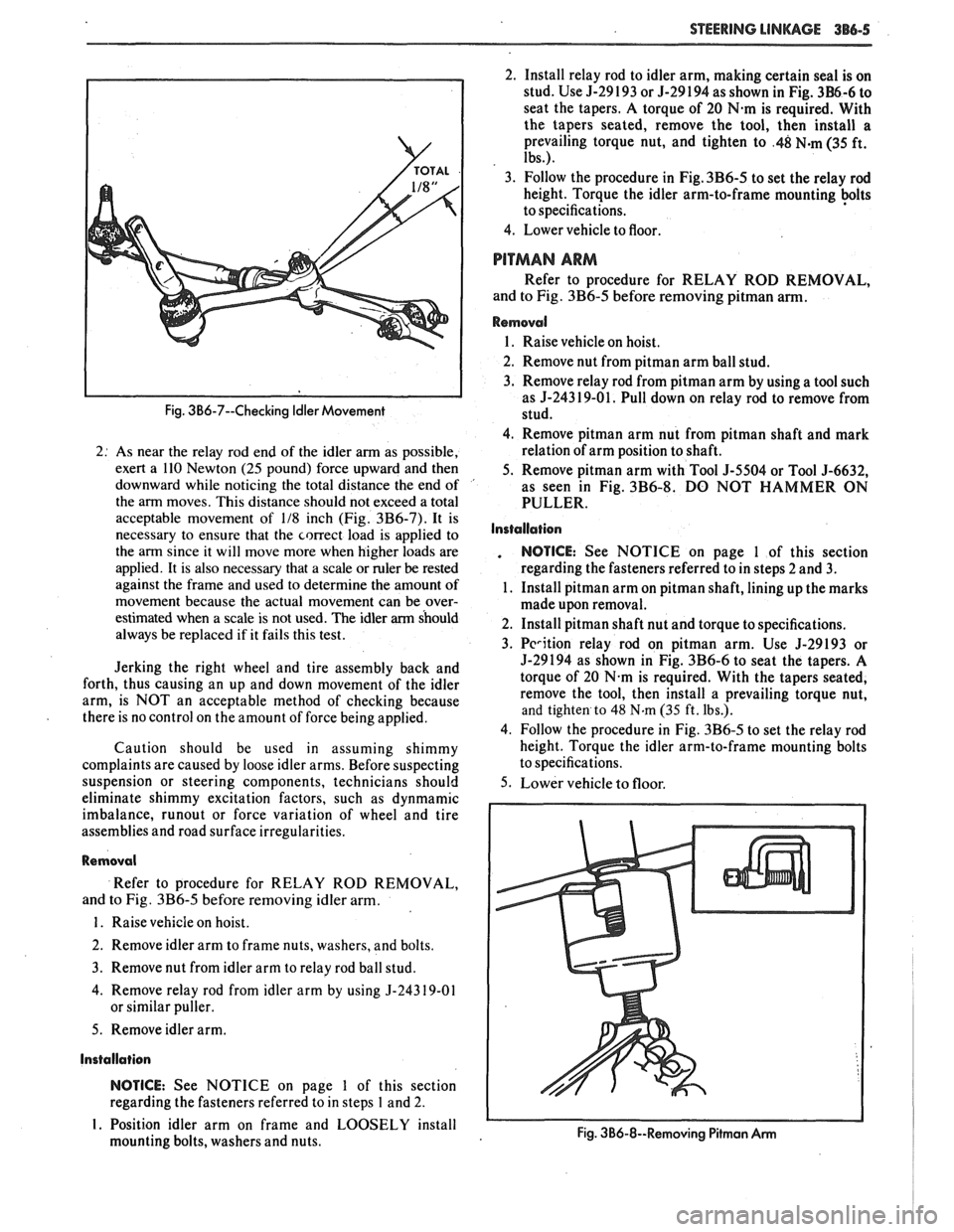
Fig. 3B6-7--Checking Idler Movement
2: As near the relay rod end of the idler arm as possible,
exert a 110 Newton
(25 pound) force upward and then
downward while noticing the total distance the end of '
the arm moves. This distance should not exceed a total
acceptable movement of
118 inch (Fig. 3B6-7). It is
necessary to ensure that the correct load is applied to
the arm since it will move more when higher loads are
applied. It is also necessary that a scale or ruler
be rested
against the frame and used to determine the amount of
movement because the actual movement can be over-
estimated when a scale is not used. The idler
arm should
always be replaced if it fails this test.
Jerking the right wheel and tire assembly back and
forth, thus causing an up and down movement of the idler
arm, is NOT an acceptable method of checking because
there is no control on the amount of force being applied.
Caution should be used in assuming shimmy
complaints are caused by loose idler arms. Before suspecting
suspension or steering components, technicians should
eliminate shimmy excitation factors, such as dynmamic
imbalance,
runout or force variation of wheel and tire
assemblies and road surface irregularities.
Removal
Refer to procedure for RELAY ROD REMOVAL,
and to Fig.
3B6-5 before removing idler arm.
1. Raise vehicle on hoist.
2. Remove idler arm to frame nuts, washers, and bolts.
3. Remove nut from idler arm to relay rod ball stud.
4. Remove relay rod from idler arm by using
5-24319-01
or similar puller.
5. Remove idler arm.
Installation
NOTICE: See NOTICE on page 1 of this section
regarding the fasteners referred to in steps
1 and 2.
I. Position idler arm on frame and LOOSELY install
mounting bolts, washers and nuts. 2.
Install relay rod to idler arm, making certain seal is on
stud. Use 5-29 193 or 5-29 194 as shown in Fig.
3B6-6 to
seat the tapers. A torque of 20
N.m is required. With
the tapers seated, remove the tool, then install a
prevailing torque nut, and tighten to
.48 N-m (35 ft.
Ibs.).
3. Follow the procedure in Fig. 3B6-5 to set the relay rod
height. Torque the idler arm-to-frame mounting
+Its
to specifications.
4. Lower vehicle to floor.
PITMAN ARM
Refer to procedure for RELAY ROD REMOVAL,
and to Fig.
3B6-5 before removing pitman arm.
Removal
1. Raise vehicle on hoist.
2. Remove nut from
pitman arm ball stud.
3. Remove relay rod from pitman arm by using a tool such
as
5-243 19-01. Pull down on relay rod to remove from
stud.
4. Remove pitman arm nut from pitman shaft and mark
relation of arm position to shaft.
5. Remove
pitman arm with Tool 5-5504 or Tool 5-6632,
as seen in Fig.
3B6-8. DO NOT HAMMER ON
PULLER.
Installation
. NOTICE: See NOTICE on page 1 of this section
regarding the fasteners referred to in steps 2 and
3.
1. Install pitman arm on pitman shaft, lining up the marks
made upon removal.
2. Install pitman shaft nut and torque to specifications.
3.
Pcrition relay rod on pitman arm. Use 5-29193 or
5-29194 as shown in Fig. 3B6-6 to seat the tapers. A
torque of 20
N.m is required. With the tapers seated,
remove the tool, then install a prevailing torque nut,
and tighten to 48 N.m (35 ft. Ibs.).
4. Follow the procedure in Fig.
3B6-5 to set the relay rod
height. Torque the idler arm-to-frame mounting bolts
to specifications.
5. Lower vehicle to floor.
Fig. 3B6-8--Removing Pitmon Arm I I
Page 195 of 1825
387-2 POWER STEERING
The effect of improperly adjusted worm thrust
bearings or an improperly adjusted over-center preload
could cause a handling stability complaint.
To properly adjust the power steering gear, the
assembly MUST be removed from the vehicle and
adjustments performed as outlined.
For removal of the power steering gear assembly
see "Power Steering Gear".
DRIVE BELT TENSION
All drive belt tension specifications can be found
in the Engine Cooling Section 6B.
When adjusting a power steering pump belt,
never pry against the pump reservoir or pull against the
filler neck. Two systems are used for belt adjustment.
On some
models, the pump is loosened from the
bracket and moved outward to increase the tension. On
other models, a half-inch square drive hole is located
in the bracket, and this hole is used to rotate the
pump-and-bracket assembly outward to increase belt
tension.
Place belt tension gage, J-23600 or equivalent
midway between the pulleys on drive belt being
checked.
POWER SKERING ADAPER GAGE J-5176-01 J-22326
PRESSURE HOSE TO
P/S GEAR PRESSURE HOSE
Figure 387-1 Test Gage Installation
To adjust pump:
1.
Loosen the pump attaching bolts and adjust the
belt to correct tension by moving the pump
outward, away from the engine.
2. Snug all pump mounting bolts and remove pry
bar.
3. Tighten all pump mounting bolts to specified
torque.
4. Check belt tension using the tension gage.
NOTICE: Do not move pump by prying against
reservoir or by pulling on filler neck, or damage
may occur.
HYDRAULIC SYSTEM CHECKS
The following procedure outlines methods to
identify and isolate power steering hydraulic circuit difficulties.
The test provides means of determining
whether power steering system hydraulic parts are
actually
defective.
Before performing hydraulic circuit test,
carefully check belt tension, fluid level and condition
of driving pulley.
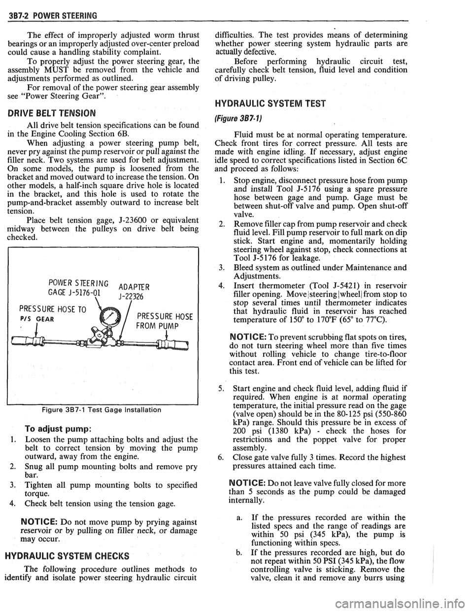
HYDRAULIC SYSTEM TEST
(Figure 387- lj
Fluid must be at normal operating temperature.
Check front tires for correct pressure. All tests are
made with engine idling. If necessary, adjust engine
idle speed to correct specifications listed in Section 6C
and proceed as follows:
1. Stop engine, disconnect pressure hose from pump
and install Tool
5-5176 using a spare pressure
hose between gage and pump. Gage must be
between shut-off valve and pump. Open shut-off
valve.
2. Remove filler cap from pump reservoir and check
fluid level. Fill pump reservoir to full mark on dip
stick. Start engine and, momentarily holding
steering wheel against stop, check connections at
Tool J-5 176 for leakage.
3. Bleed system as outlined under Maintenance and
Adjustments.
4. Insert thermometer (Tool J-5421) in reservoir
filler opening. Move
/steering (wheel/ from stop to
stop several times until thermometer indicates
that hydraulic fluid in reservoir has reached
temperature of
150" to 170°F (65" to 77°C).
N OTI G E: To prevent scrubbing flat spots on tires,
do not turn steering wheel more than five times
without rolling vehicle to change tire-to-floor
contact area. Front end of vehicle can be lifted for
this test.
5. Start engine and check fluid level, adding fluid if
required. When engine is at normal operating
temperature, the initial pressure read on the gage
(valve open) should be in the 80-125 psi (550-860
kPa) range. Should this pressure be in excess of
200 psi (1380
kPa) - check the hoses for
restrictions and the poppet valve for proper
assembly.
6. Close gate valve fully
3 times. Record the highest
pressures attained each time.
N OTI C E: Do not leave valve fully closed for more
than
5 seconds as the pump could be damaged
internally.
a. If
the pressures recorded are within the
listed specs and the range of readings are
within 50 psi (345
kPa), the pump is
functioning within specs.
b. If the pressures recorded are high, but do
not repeat within 50 PSI (345
kPa), the flow
controlling valve is sticking. Remove the
valve, clean it and remove any burrs using