sensor PONTIAC FIERO 1988 Service Owner's Manual
[x] Cancel search | Manufacturer: PONTIAC, Model Year: 1988, Model line: FIERO, Model: PONTIAC FIERO 1988Pages: 1825, PDF Size: 99.44 MB
Page 516 of 1825
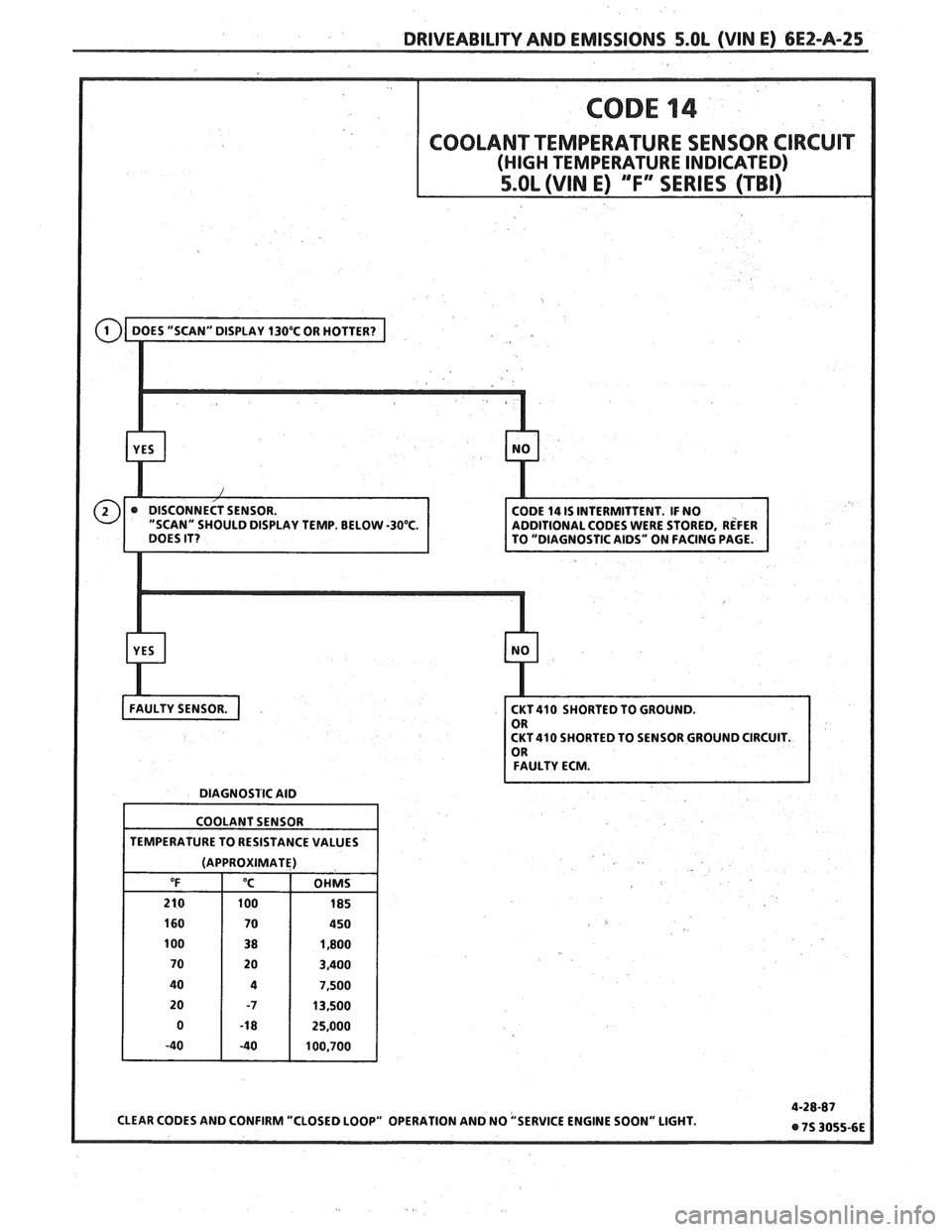
DRIVEABILITY AND EMISSIONS 5.OL (VIN E) 6E2-A-25
LAY TEMP. BELOW -30°C.
CKT 410 SHORTED TO SENSOR GROUND CIRCUIT.
FAULTY ECM.
DIAGNOSTIC AID
COOLANT SENSOR
TEMPERATURE TO RESISTANCE VALUES
(APPROXIMATE)
Page 517 of 1825
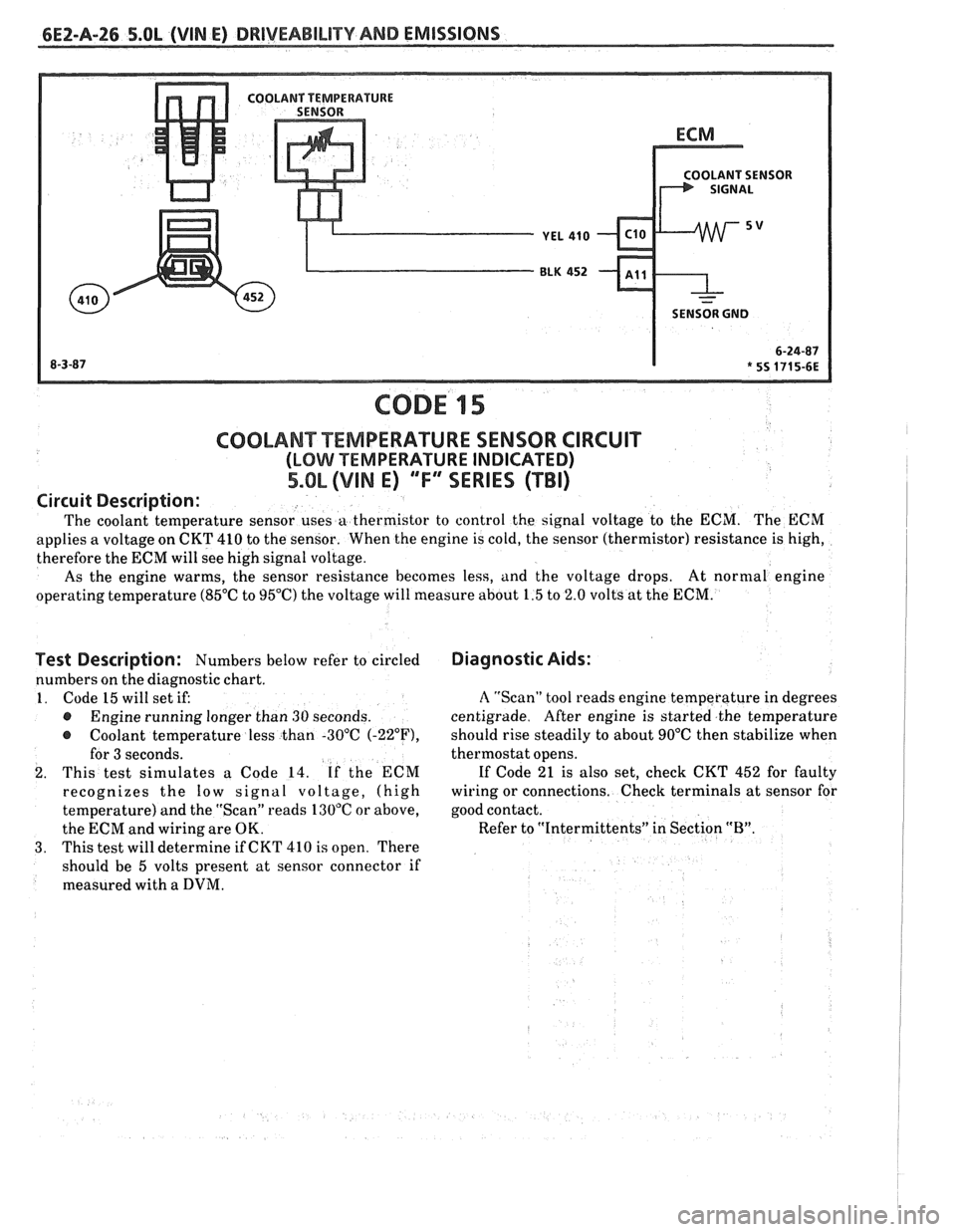
6EZ-A-26 5.8L (VIN E) DRIVEABILITY AND EMISSIONS
OLANT SENSOR
SENSOR GND
CODE 15
Test Description: Numbers below refer to circled
numbers on the diagnostic chart.
1. Code 15 will set if:
@ Engine running longer than 30 seconds.
@ Coolant temperature less than -30°C (-22"F),
for 3 seconds.
2. This test simulates a Code 14. If the ECM
recognizes the
low signal voltage, (high
temperature) and the "Scan" reads 130°C or above,
the ECM and wiring are OK.
3. This test will determine if CKT 410 is open. There
should be 5 volts present at sensor connector if
measured with a
DVM.
COOLANT TEMPERATURE SENSOR CIRCUIT
(LOMI TEMPERATURE INDICATED)
5.OL (VIM E) ""FYERIES (TBI)
Diagnostic Aids:
Circuit
Description:
The coolant temperature sensor uses a thermistor to control the signal voltage to the ECM. The ECM
applies a voltage on CKT 410 to the sensor. When the engine is cold, the sensor (thermistor) resistance is high,
therefore the ECM will see high signal voltage.
As the engine warms, the sensor resistance becomes less, and the voltage drops. At
normal engine
operating temperature (85°C to 95°C) the voltage will measure about 1.5 to 2.0 volts at the ECM.
A "Scan" tool reads engine temperature in degrees
centigrade. After engine is started the temperature
should rise steadily to about 90°C then stabilize when
thermostat opens.
If Code 21 is also set, check CKT 452 for faulty
wiring or connections. Check terminals at sensor for
good contact.
Refer to "Intermittents" in Section
"B".
~
Page 518 of 1825
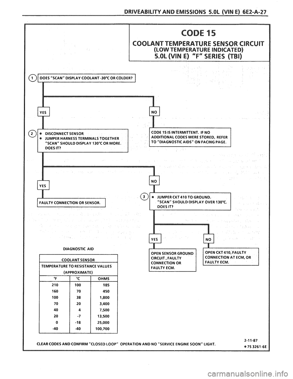
DRIVEABILITY AND EMISSIONS S.OL (VIN E) 6E2-A-27
" SHOULD DISPLAY 130°C OR MORE.
DIAGNOSTIC AID
CLEAR CODES AND CONFIRM "CLOSED LOOP" OPERATION AND NO "SERVICE ENGINE SOON" LIGHT.
COOLANT
SENSOR
TEMPERATURE TO RESISTANCE VALUES
(APPROXIMATE)
"F "C OHMS
210 100 185
160 70 450
100 38 1,800
70 20 3,400
40
4 7,500
20 -7 13,500
0
-1 8 25,000
-40 -40 100,700
Page 519 of 1825
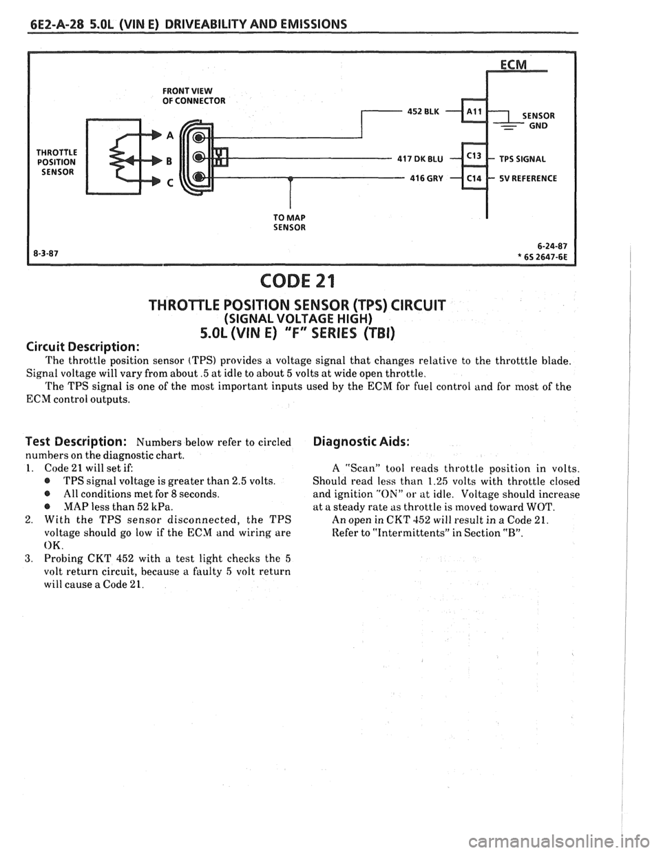
6EZ-A-28 5.OL (VIN E) DRIVEABILITY AND EMISSIONS
FRONT VIEW OF CONNECTOR
5V REFERENCE
TO
MAP SENSOR
CODE 21
THROTLE POSITION SENSOR (TPS) CIRCUIT
(SIGNAL VOLTAGE HIGH)
5.OL (VIN E) "F" "SERIES ("FBI)
Circuit Description:
The throttle position sensor (TPS) provides a voltage signal that changes relative to the throtttle blade.
Signal voltage will vary from about
.5 at idle to about 5 volts at wide open throttle.
The TPS signal is one of the most important inputs used by the ECM for fuel control and for most of the
ECM control outputs.
Test Description: Numbers below refer to circled
numbers on the diagnostic chart.
1. Code
21 will set if:
@ TPS signal voltage is greater than 2.5 volts.
@ All conditions met for 8 seconds.
@ MAP less than 52 kPa.
2. With the TPS sensor disconnected, the TPS
voltage should go low if the ECM and wiring are
OK.
3. Probing CKT 452 with a test light checks the 5
volt return circuit, because a faulty 5 volt return
will cause
a Code 21.
Diagnostic Aids:
A ''Scan" tool reads throttle position in volts.
Should read less than 1.26 volts with throttle closed
and ignition
"Oili" or at idle. Voltage should increase
at a steady rate as throttle is moved toward
WOT.
An open in CKT 152 will result in a Code 21.
Refer to
"Intermittents" in Section "B".
Page 521 of 1825
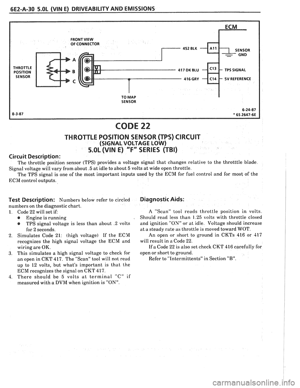
FRONT VIEW OF CONNECTOR
5V REFERENCE
SENSOR
CODE 22
THROTTLE POSITION SENSOR (TPS) CIRCUIT
(SIGNAL VOLTAGE LOW)
5.OL (VIN E) "'F3ERIES (TBI)
Circuit Description:
The throttle position sensor (TPS) provides a voltage signal that changes relative to the throtttle blade.
Signal voltage will vary from about
.5 at idle to about 5 volts at wide open throttle.
The TPS signal is one of the most important inputs used
by the ECM for fuel control and for most of the
ECM control outputs.
Test Description: Numbers below refer to circled
numbers on the diagnostic chart.
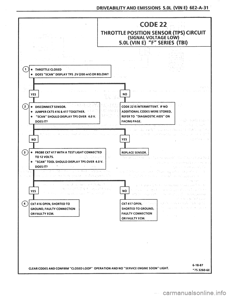
1. Code 22 will set if:
Engine is running
r TPS signal voltage is less than about .2 volts
for
2 seconds.
2. Simulates Code 21: (high voltage) If the ECM
recognizes the high signal voltage the ECM and
wiring are OK.
3. This simulates a high signal voltage to check for
an open in CKT 417. The "Scan" tool will not read
up to 12 volts, but what's important is that the
ECM recognizes the signal on CKT 417.
4. There should be
5 volts at terminal "C" if
measured with a DVM when ignition is "ON".
Diagnostic Aids:
A "Scan" tool reads throttle position in volts.
Should read less than 1.25 volts with throttle closed
and ignition "ON" or at idle. Voltage should increase
at a steady rate as throttle is moved toward WOT.
An open
or short to ground in CKTs 416 or 417
will result in a Code 22.
If a Code 22 is also set check CKT 416 carefully for
open or short to ground.
Refer to "Intermittents" in Section
"B".
Page 522 of 1825
DRIVEABILITY AND EMISSIONS 5.OL (VIN E) 6EZ-A-31
THROTTLE POSITION SENSOR (TPS) CIRCUIT
ODE 22 IS INTERMITTENT. IF NO
@ JUMPER CKTS 416 & 417 TOGETHER. DDlTlONAL CODES WERE STORED,
@ "SCAN" SHOULD DISPLAY TPS OVER 4.0 V. EFER TO "DIAGNOSTIC AIDS" ON
TO
12 VOLTS.
Page 523 of 1825
6E2-A-32 S.OL (VIN E) DRIVEABILITY AND EMISSIONS
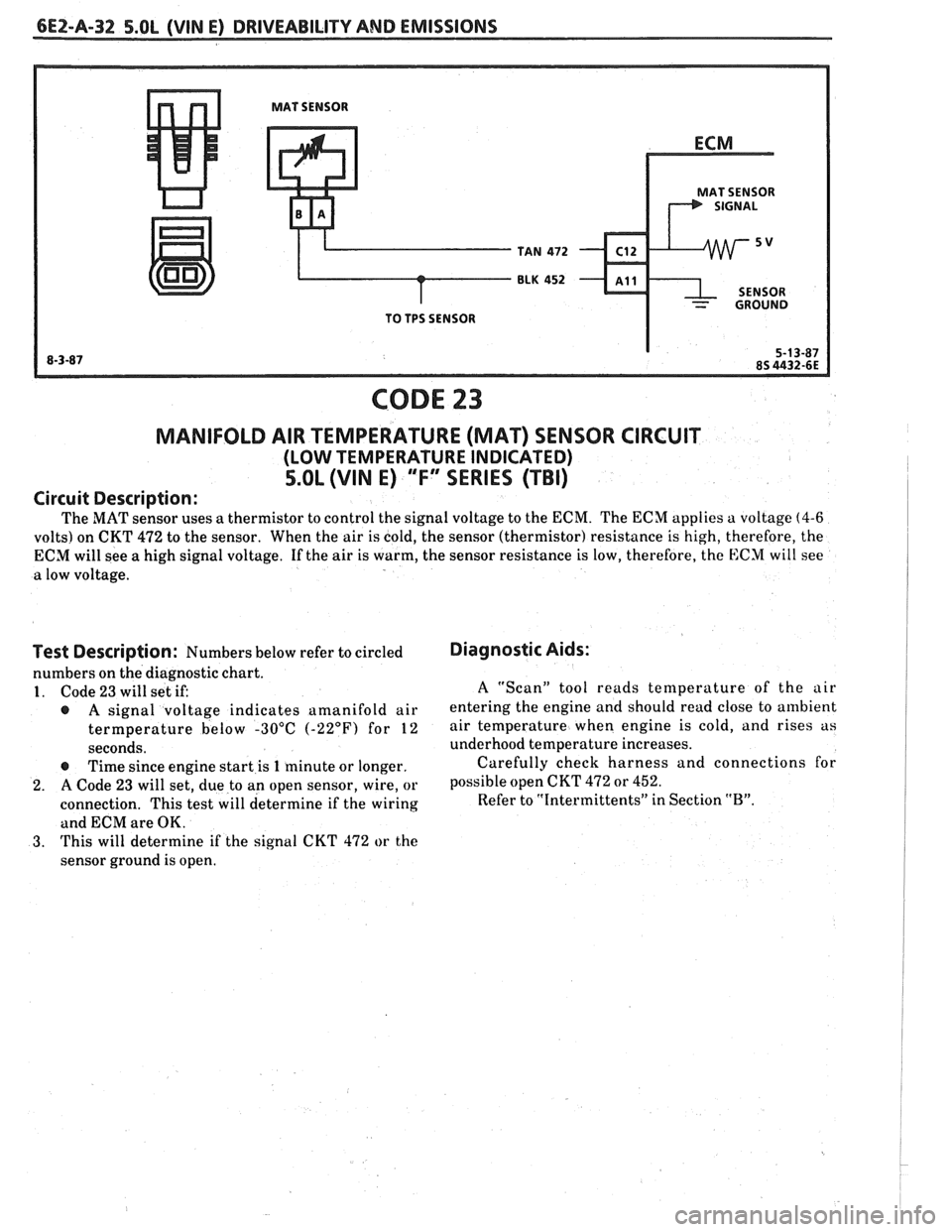
MAT SENSOR
MAT SENSOR
TAN
472 C12
BLK 452 - ~11
- GROUND
TO TPS SENSOR
CODE 23
MANIFOLD AIR TEMPERATURE (MAT) SENSOR CIRCUIT
(LOW TEMPERATURE INDICATED)
5.OL (VIN E) "F" SERIES (TBI)
Circuit Description:
The MAT sensor uses a thermistor to control the signal voltage to the ECM. The ECM applies a voltage (4-6
volts) on CKT 472 to the sensor. When the air is cold, the sensor (thermistor) resistance is high, therefore, the
ECM will see a high signal voltage. If the air is warm, the sensor resistance is low, therefore, the
E:CM will see
a low voltage.
i
Test Description: Numbers below refer to circled
numbers on the diagnostic chart.
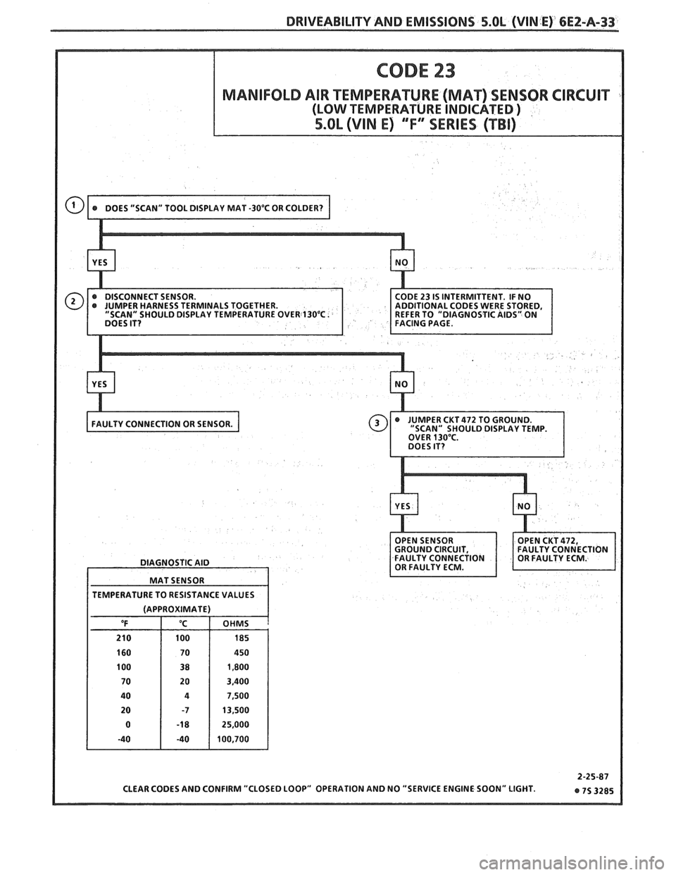
1. Code 23 will set if:
@ A signal voltage indicates amanifold air
termperature below -30°C
(-22°F) for 12
seconds.
@ Time since engine start is 1 minute or longer.
2. A Code 23 will set, due to an open sensor, wire, or
connection. This test will determine if the wiring
and ECM are OK.
3. This will determine if the signal CKT 472 or the
sensor ground is open.
Diagnostic Aids:
A "Scan" tool reads temperature of the air
entering the engine and should read close to ambient
air temperature when engine is cold, and rises as
underhood temperature increases.
Carefully check harness and connections for
possible open CKT
472 or 452.
Refer to "Intermittents" in Section "B".
Page 524 of 1825
DRIVEABILITY AND EMISSIONS 5.OL (VIN E) 6E2-A-33
DIAGNOSTIC AID
MAT SENSOR
TEMPERATURE TO RESISTANCE VALUES
(APPROXIMATE) OHMS
a
Page 525 of 1825
6EZ-A-34 5.OL (WIN E) DRIVEABILITY AND EMISSIONS
ECM
I.P.
8RN 437
K 7 PIN SIGNAL
PIN SWITCH
r ELK450 12v
1 CLOSED IN - 15- WAY .I.P. CONNECTOR - - PARK OR NEUTRAL I
CODE 24
VEHICLE SPEED SENSOR (VSS) CIRCUIT
5.OL (VIN E) "F" SERIES (TBI)
Circuit Description:
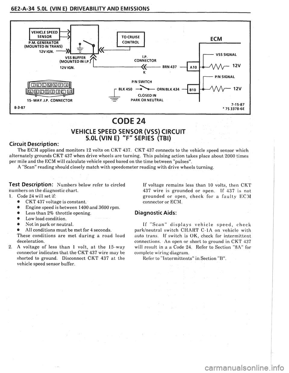
The ECM applies and monitors 12 volts on CKT 437. CKT 437 connects to the vehicle speed sensor which
alternately grounds CKT
437'when drive wheels are turning. This pulsing action takes place about 2000 times I
per mile and the ECM will calculate vehicle speed based on the time between "pulsesJ'.
A "Scan" reading should closely match with speedometer reading with drive wheels turning.
I
Test Description: Numbers below refer to circled
numbers on the diagnostic chart.
1. Code 24 will set if:
@ CKT 437 voltage is constant.
@ Engine speed is between 1400 and 3600 rpm.
@ Less than 2% throttle opening.
@ Low load condition.
@ Not in park or neutral.
@ All conditions must be met for 4 seconds.
These conditions are met during a road load
deceleration.
2.
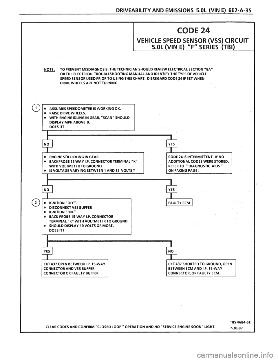
A voltage of less than 1 volt, at the 15-way
connector indicates that the CKT 437 wire
may be
shorted to ground.
Disconnect CKT 437 at the
vehicle speed sensor buffer. If
voltage remains less than 10 volts, then CKT
437 wire is grounded or open.
If 437 is not
grounded or open, check for a faulty
KCYI
connector or ECM.
Diagnostic Aids:
If "Scan" displays vehicle speed, check
parWneutra1 switch CHART C-LA on vehicle with
auto trans.
If switch is OK, check for intermittent
connections.
An open or short to ground in CKT 437
will result in
a a Code 24. Refer to Section "$A" for
col~lplete wiring diagram.
Refer to
"[ntermittents" in Section "B".
Page 526 of 1825
DRIVEABILITY AND EMISSIONS 5.OL (WIN E) 6E2-A-35
NOTE: TO PREVENT MISDIAGNOSIS, THE TECHNICIAN SHOULD REVIEW ELECTRICAL SECTION "8A"
OR THE ELECTRICAL TROUBLESHOOTING MANUAL AND IDENTIFY THE TYPE OF VEHICLE
SPEED SENSOR USED PRIOR TO USING THIS CHART. DISREGARD CODE
24 IF SET WHEN
DRIVE WHEELS ARE NOT TURNING.
CTOR TERMINAL "K"
e IGNITION "ON." @ BACK PROBE 15-WAY I.P. CONNECTOR
ISPLAY 10 VOLTS OR MORE.
ONNECTOR AND
VSS BUFFER
CLEAR CODES AND CONFIRM "CLOSED LOOP
" OPERATION AND NO "SERVICE ENGINE SOON" LIGHT.