sensor PONTIAC FIERO 1988 Service Service Manual
[x] Cancel search | Manufacturer: PONTIAC, Model Year: 1988, Model line: FIERO, Model: PONTIAC FIERO 1988Pages: 1825, PDF Size: 99.44 MB
Page 540 of 1825
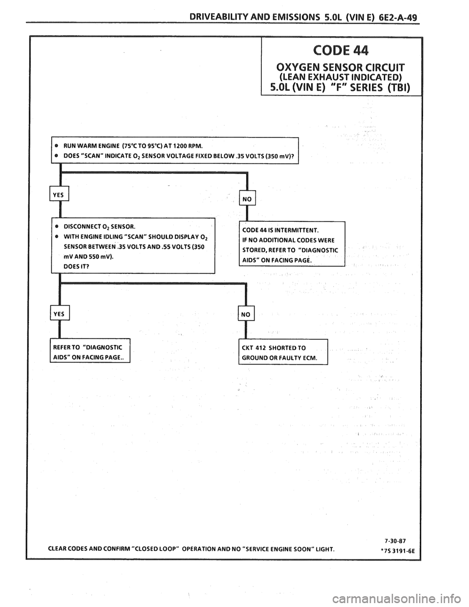
@ WITH ENGINE IDLING "SCAN" SHOULD DISPLAY O2
SENSOR BETWEEN .35 VOLTS AND .55 VOLTS (350
Page 541 of 1825
6EZ-A-50 5.0b (VIN E) DRIVEABILITY AND EMISSIONS
- GROUND -
CODE 45
OXYGEN SENSOR CIRCUIT
(RICH EXHAUST INDICAnEB)
5.OL (VlN E) ""FYESEBIES (TBI)
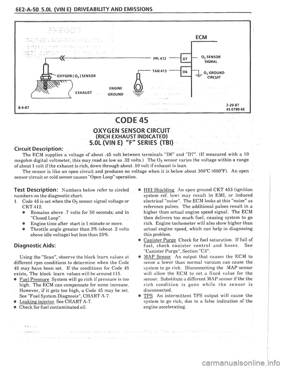
Circuit Description:
The ECM supplies a voltage of about .45 volt between terminals "D6" and "D7". (If measured with a 10
megohm digital voltmeter, this may read as low as .32 volts.) The
O2 sensor varies the voltage within a range
of about
1 volt if the exhaust is rich, down through about .10 volt if exhaust is lean.
The sensor is like an open circuit and produces no voltage when it is below about 360°C (600°F). An open
sensor circuit or cold sensor causes "Open Loop" operation.
Test Description: Numbers below refer to circled
numbers on the diagnostic chart.
1. Code 45 is set when the O2 sensor signal voltage or
CKT
422.
@ Remains above .7 volts for 50 seconds; and in
"Closed Loop".
@ Engine time after start is 1 minute or more.
@ Throttle angle greater than 2% (about .2 volts
above idle voltage) but less than 25%.
Diagnostic Aids:
Using the "Scan", observe the block learn values at
different rpm conditions to determine when the
Code
45 may have been set. If the conditions for Code 45
exists, The block learn values will be around 115.
@ Fuel Pressure System will go rich if pressure is too
high. The ECM can compensate for some increase.
However, if it gets too high, a Code 45
may be set.
See "Fuel System Diagnosis", CHART
A-7.
Q See CHART A-7.
@ Check for fuel contaminated oil.
@ HE1 Shielding An open ground CKT 453 (ignition
system ref. low) may result in EMI, or induced
electrical "noise". The ECM looks
at this "noise" as
reference pulses. The additional pulses result in a
higher than actual engine speed signal. The ECM
then delivers too much fuel, causing system to go
rich. Engine tachometer will also show higher than
actual engine speed, which can help in diagnosing
this problem.
@ Canister Purge Check for fuel saturation. If full of
fuel, check canister control and hoses. See
"Canister Purge", Section
"(23".
@ MAP Sensor An output that causes the ECM to
sense a lower than normal
vacuum can cause the
system to go rich. Disconnecting the MAP sensor
will allow the ECM to set
a fixed value for the
sensor. Substitute a different MAP sensor if the the
rich condition is gone while the sensor is
disconnected.
r TPS An intermittent TPS output will cause the
system to go rich, due to
a false indication of the
engine accelerating.
Page 549 of 1825
6EZ-B-2 5.OL (VIN E) DRIVEABILITY AND EMISSIONS
Problem may or may not turn "ON" the "Service Engine Soon" light, or store a code.
DO NOT use the trouble code charts in Section
"A" for intermittent problems. The fault must be
present to locate the problem. If a fault is
intermittent, use of trouble code charts may result
in replacement of good parts.
@ Most intermittent problems are caused by faulty
electrical connections or wiring. Perform
careful check of suspect circuits for:
- Poor mating of the connector halves, or
terminals, not fully seated in the connector
body (backed out).
I - Improperly formed or damaged terminals.
All connector terminals in problem circuit
should be carefully reformed to increase
contact tension.
- Poor terminal to wire connection. This
requires removing the terminal from the
connector body to check as outlined in the
Introduction to Section
"6E".
@ If a visual (physical) check does not find the
cause of the problem, the car can be driven with
a voltmeter connected to a suspected circuit or a
"Scan" tool may be used. An abnormal voltage
reading, when the problem occurs, indicates the
problem may be in that circuit. If the wiring
and connectors check OK, and a trouble code was
stored for a circuit having a sensor, except
for Codes 44 and 45, substitute a known good
sensor and recheck.
@ Loss of trouble code memory. To check,
disconnect TPS and idle engine until "Service
Engine Soon" light comes
"ON". Code 22 should
be stored, and kept in memory, when ignition is
turned "OFF" for at least 10 seconds. If not, the
ECM
is faulty.
@ An intermittent "SES" light, and no trouble
codes, may be caused by:
- Electrical system interference caused by a
defective relay, ECM driven solenoid, or switch.
They can cause a sharp electrical surge.
Normally, the problem will occur when the
faulty component is operated.
- Improper installation of electrical options, such
as lights, 2-way radios, etc.
- EST wires should be routed away from spark
plug wires, ignition system components, and
generator. Wire for CKT 453 from ECM to
ignition system should be a good ground.
- Ignition secondary shorted to ground.
- CKTs 419 ("SES" light) or 451 (Diagnostic Test)
intermittently shorted to ground.
- ECM power grounds.
HARD START
Definition: Engine cranks OK, but does not start for a long
time. Does eventually run, or may start but immediately dies.
, <
@ CHECK: 4. Connect a radiator test pump to the line and
- For water contaminated fuel. apply 103 kPa (15 psi) pressure. If the
- Fuel system pressure CHART A-7. pressure will hold for 60 seconds, the check
- TPS for sticking or binding should read less than
valve is OK.
1.25 volts on a "Scan" tool. @ Check ignition system for:
- No crank signal; see CHART C-1B. - Proper output with ST-125.
- EGR operation; CHART C-7. - Worn shaft.
- Fuel System - CHART A-7. - Rare and shorted wires.
- For a faulty in-tank fuel pump check valve, - Pickup coil resistance and connections.
which would allow the fuel in the lines to drain
- Loose ignition coil connections.
back to the tank after the engine is stopped. To
- Moisture in distributor cap.
check for this condition:
- Spark plugs, wet plugs, cracks, wear,
1. Ignition "OFF".
improper gap, burned electrodes, or heavy
2. Disconnect fuel line at the filter
deposits.
3. Remove the tank filler cap. @ If engine starts but then, immediately stalls,
open distributor bypass line. If engine then
starts, and runs OK, replace distributor pickup
coil.
@ Check CKT 423 (EST) for short to ground.
Page 550 of 1825
DRIVEABILITY AND EMISSIONS 5.OL (VIN E) 6E2-B-3
SURGES AND/OR CHUGGLE
Definition: Engine power variation, under steady
throttle or cruise. Feels like the car speeds up and slows
down, with no change in the accelerator pedal.
@ Use a "Scan" tool to make sure reading of VSS
matches vehicle speedometer. See "Special
Information", Section
"6E".
e CHECK:
- For intermittent EGR at idle. See appropriate
CHART C-7.
- Ignition timing. See Emission Control
Information label.
- Inline fuel filter for dirt or restriction.
- Fuel pressure. See CHART A-7.
- Generator output voltage. Repair if less than 9,
or more than
16 volts.
- TCC Operation. CHART C-8A.
@ Inspect oxygen sensor for silicon contamination
from fuel, or use of improper RTV sealant. The
sensor may have a white, powdery
coabing and
result in a high but false signal voltage (rich
exhaust indication). The ECM will then reduce
the amount of fuel delivered to the engine,
causing a severe driveability problem.
@ Remove spark plugs. Check for cracks, wear,
improper gap, burned electrodes, or heavy
deposits. Also, check condition of the rest of the
ignition system.
LACK OF BOWER, SLUGGISH, OR SPONGY
Definition: Engine delivers less than expected power. Little or no
increase in speed, when accelerator pedal is pushed down part way.
@ Compare customer's car to similar unit. Make - For restricted fuel filter, contaminated fuel or
sure the customer's car has an actual problem. improper fuel pressure. See CHART A-7.
@ Remove air cleaner and check air filter for dirt, - ECM Grounds.
or for being plugged. Replace as necessary.
- EGR operation for being open, or partly open, all
If there is spray from only one injector, then, the time
- CHART C-7.
there is a malfunction in the injector assembly,
- Generator output voltage. Repair if less than 9, or
or in the signal to the injector assembly.
'I'he more than 16 volts.
malfunction can be isolated, by switching the
- Engine valve timing and compression.
injector connectors.
If the problem remains with - Engine, for proper or worn camshaft. See Section
the original injector, after switching the
"6A".
connector, then the injector is defective. Replace - Transmission torque converter operation. See
the injector. If the problem moves with the
Sectionw7A".
injector connector, then the problem is an - Secondary ignition voltage.
improper signal in the injector circuits, see
- Proper operation or ESC. See Section "C5".
CHART A-3. @ Check exhaust system for restriction. See
@ CHECK: CHART B- 1.
- Ignition timing. See Emission Control
Information label.
Page 551 of 1825
6EZ-B-4 5.OL (VIN E) DRIVEABILITY AND EMISSIONS
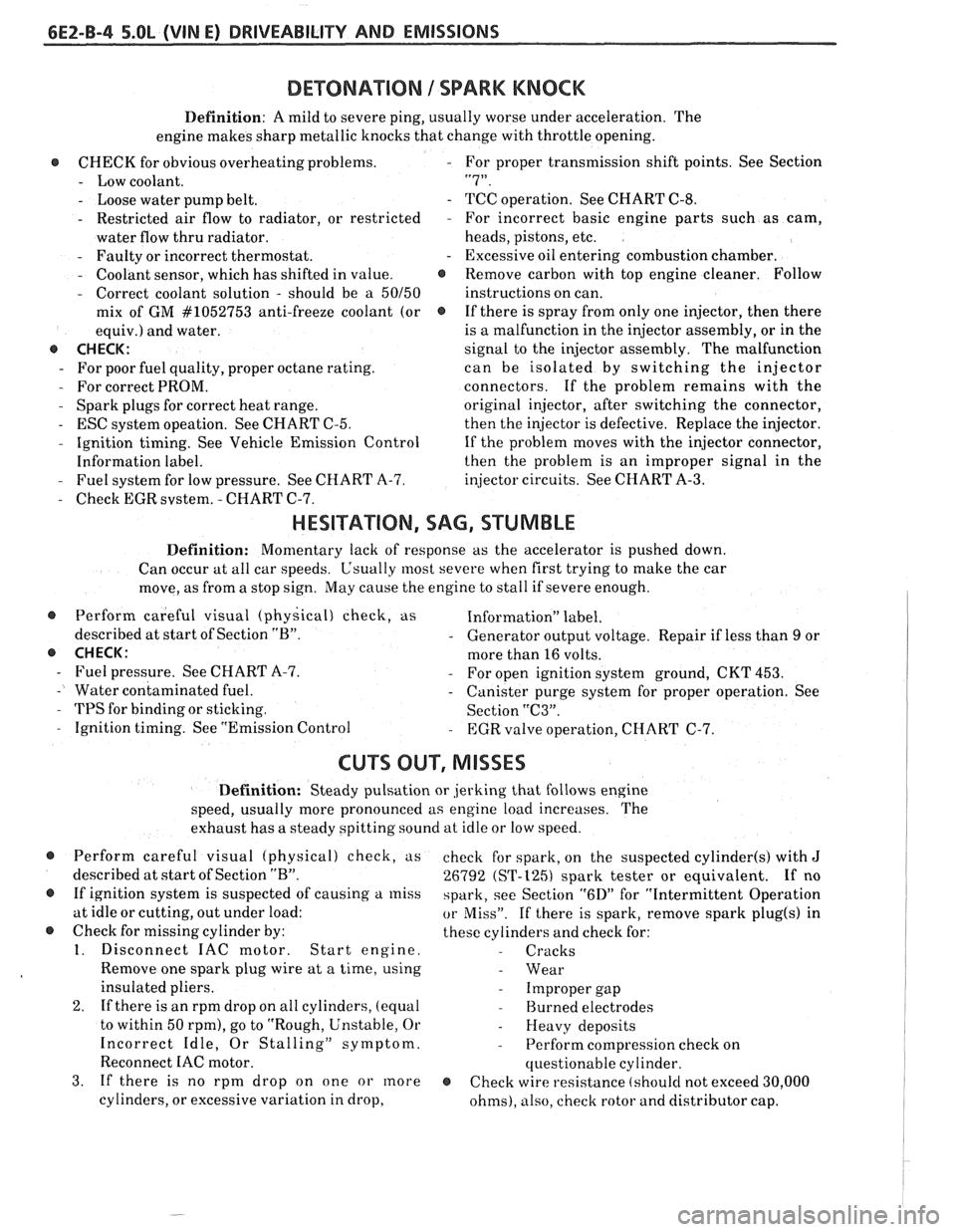
DEWNATION 1 SPARK KNOCK
Definition: A mild to severe ping, usually worse under acceleration. The
engine makes sharp metallic knocks that change with throttle opening.
@ CHECK for obvious overheatingproblems. - For proper transmission shift points. See Section
- Low coolant. "7".
- Loose water pump belt. - TCC operation. See CHART C-8.
- Restricted air flow to radiator, or restricted - For incorrect basic engine parts such as cam,
water flow thru radiator. heads,
pistons, etc.
- Faulty or incorrect thermostat. - Excessive oil entering combustion chamber.
- Coolant sensor, which has shifted in value. @ Remove carbon with top engine cleaner. Follow
- Correct coolant solution - should be a 50150 instructions on can.
mix of GM
#lo52753 anti-freeze coolant (or @ If there is spray from only one injector, then there
equiv.) and water. is
a malfunction in the injector assembly, or in the
@ CHECK: signal to the injector assembly. The malfunction
- For poor fuel quality, proper octane rating. can be isolated by switching the injector
- For correct PROM. connectors. If the problem remains with the
- Spark plugs for correct heat range.
original injector, after switching the connector,
- ESC system opeation. See CHART C-5.
then the injector is defective. Replace the injector.
- Ignition timing. See Vehicle Emission Control
If the problem moves with the injector connector,
Information label. then the
problem is an improper signal in the
- Fuel system for low pressure. See CHART A-7.
injector circuits. See CHART A-3.
- Check EGR svstem. - CHART C-7.
HESITATION, SAG, STUMBLE
Definition: Momentary lack of response as the accelerator is pushed down.
Can occur at all car speeds.
C'sually most severe when first trying to make the car
move, as from a stop sign.
May cause the engine to stall if severe enough.
@ Perform careful visual (physical) check, as Information" label.
described at start of Section
"B". - Generator output voltage. Repair if less than 9 or
@ CHECK: more than 16 volts.
- Fuel pressure. See CHART A-7. - For open ignition system ground, CKT 453.
- Water contaminated fuel. - Canister purge system for proper operation. See
- TPS for binding or sticking.
Section "C3".
- Ignition timing. See "Emission Control - EGR valve operation, CHART C-7.
CU"F OUT, MISSES
Definition: Steady pulsation or jerking that follows engine
speed, usually more pronounced as engine load increases. The
exhaust has a steady spitting sound at idle or low speed.
@ Perform careful visual (physical) check, us
described at start of Section
"B".
@ If ignition system is suspected of causing a miss
at idle or cutting, out under load:
@ Check for missing cylinder by:
1. Disconnect IAC motor. Start engine.
Remove one spark plug wire at a time, using
insulated pliers.
2. If there is an rpm drop on all cylinders, (equal
to within 50
rpm), go to "Rough, Unstable, Or
Incorrect Idle, Or Stalling" symptom.
Reconnect
IAC motor.
3. If there is no rpm drop on one or more
cylinders, or excessive variation in drop, check
for spark, on the suspected
cylinder(s) with J
26792 (ST-1251 spark tester or equivalent. If no
spark, see Section
"6D" for "Intermittent Operation
or Miss". If there is spark, remove spark plug(s) in
these cylinders and check for:
- Cracks
- Wear
- Improper gap
- Burned electrodes
- Heavy deposits
- Perform compression check on
questionable cylinder.
@ Check wire resistance (shoulcl not exceed 30,000
ohms), also, check rotor and distributor cap.
Page 553 of 1825
6E2-8-6 5.OL (VIN E) DRIVEABILITY AND EMISSIONS
- MAP Sensor - Ignition "ON", engine stopped.
Compare MAP voltage with known good vehicle.
-
Voltage should be the same + 400 mV (.4 volts).
OR
Start and idle engine. Disconnect
sensor
electrical connector. If idle improves, substitute
a known good sensor and recheck.
- A/C refrigerant pressure too high. Check for
overcharge or faulty pressure switch.
- PCV valve for proper operation by placing finger
over inlet hole in valve end several times. Valve
should snap back. If not, replace valve.
Run a cylinder compression check See Section
" 6".
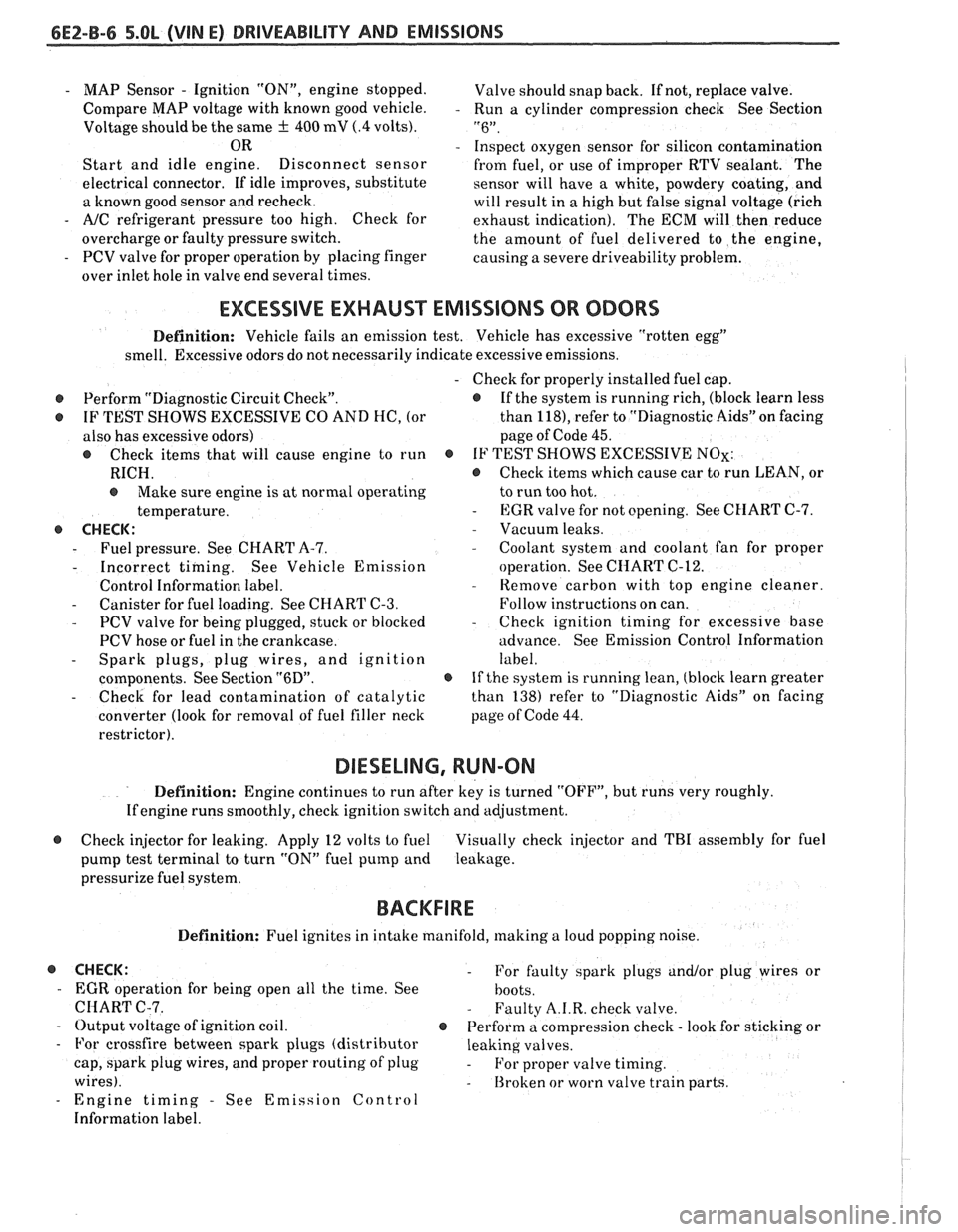
Inspect oxygen sensor for silicon contamination
from fuel, or use of improper RTV sealant. The
sensor will have a white, powdery coating, and
will result in a high but false signal voltage (rich
exhaust indication). The ECM will then reduce
the amount of fuel delivered to the engine,
causing a severe driveability problem.
EXCESSIVE EXHAUST EMISSIONS OR ODORS
Definition: Vehicle fails an emission test. Vehicle has excessive "rotten egg"
smell. Excessive odors do not necessarily indicate excessive emissions.
@ Perform "Diagnostic Circuit Check".
@ IF TEST SHOWS EXCESSIVE CO AND HC, (or
also has excessive odors)
@ Check items that will cause engine to run
RICH.
e Make sure engine is at normal operating
temperature.
o CHECK:
- Fuel pressure. See CHART A-7.
- Incorrect timing. See Vehicle Emission
Control Information label.
- Canister for fuel loading. See CHART C-3.
- PCV valve for being plugged, stuck or blocked
PCV hose or fuel in the crankcase.
- Spark plugs, plug wires, and ignition
components. See Section
"6D".
- Check for lead contamination of catalytic
converter (look for removal of fuel filler neck
restrictor).
- Check for properly installed fuel cap.
@ If the system is running rich, (block learn less
than
1181, refer to "Diagnostic Aids" on facing
page of Code
45.
o IF TEST SHOWS EXCESSIVE NOx:
@ Check items which cause car to run LEAN, or
to run too hot.
- EGR valve for not opening. See CHART C-7.
- Vacuum leaks. - Coolant system and coolant fan for proper
operation. See
CHART C-12.
- Remove carbon with top engine cleaner.
Follow instructions on can.
- Check ignition timing for excessive base
advance. See Emission Control Information
label.
@ If the system is running lean, (block learn greater
than
138) refer to "Diagnostic Aids" on facing
page of Code
44.
DIESELING, RUN-ON
Definition: Engine continues to run after key is turned "OFF", but runs very roughly.
Ifengine runs smoothly, check ignition switch and adjustment.
@ Check injector for leaking. Apply 12 volts to fuel Visually check injector and TBI assembly for fuel
pump test terminal to turn "ON" fuel pump and leakage.
pressurize fuel system.
BACKFIRE
Definition: Fuel ignites in intake manifold, making a loud popping noise.
@ CHECK: - For faulty spark plugs and/or plug wires or
- EGR operation for being open all the time. See
hoots.
CHART C-7. - Faulty A.I.R. check valve.
- Output voltage of ignition coil. @ Perform a compression check - look for sticking or
- For crossfire between spark plugs (distributor leaking valves.
cap, spark plug wires, and proper routing' of plug
- For proper valve timing.
wires).
- Broken or worn valve train parts.
- Engine timing - See Emission Control
Information label.
Page 554 of 1825
DRIVEABILITY AND EMISSIONS 5.OL (VIN E) 6EZ-B-7
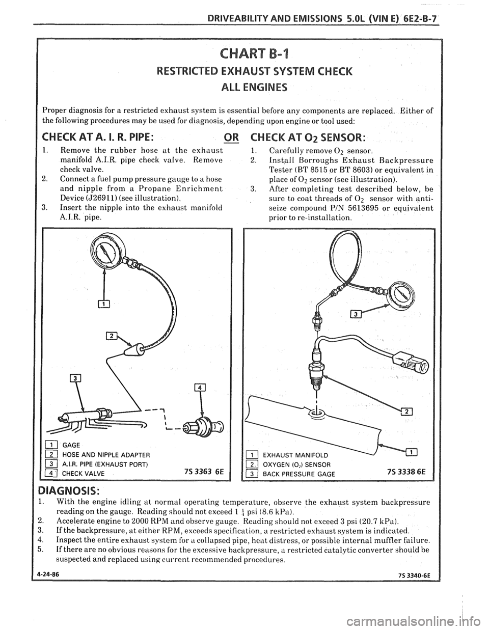
RESTRICTED EXHAUST SYSTEM CHECK
ALL ENGINES
Proper diagnosis for a restricted exhaust system is essential before any components are replaced. Either of
the following procedures may be used for diagnosis, depending upon engine or tool used:
CHECK AT A. I. R. PIPE: - OR CHECK A"F2 SENSOR:
1. Remove the rubber hose at the exhaust 1. Carefully remove O2 sensor.
manifold
A.I.R. pipe check valve. Remove 2. Install Borroughs Exhaust Rackpressure
Tester
(FIT 8515 or BT 8603) or equivalent in
2. Connect a fuel pump pressure gauge to a hose
place of Oz sensor (see illustration).
and nipple from a Propane Enrichment
3. After completing test described below, be
Device
(526911) (see illustration).
sure to coat threads of O2 sensor with anti-
3. Insert the nipple into the exhaust manifold
seize compound PIN 5613695 or equivalent
prior to re-installation.
1. With the engine idling at normal operating temperature, observe the exhaust system backpressure
reading on the gauge. Reading should not exceed
1 t psi (8.6 kPa).
2. Accelerate engine to 2000 RPM and observe gauge. Reading should not exceed 3 psi (20.7 kPa).
3.
If the backpressure, at either RPM, exceeds specification, a restricted exhaust system is indicated.
4. Inspect the entire exhaust system for a collapsed pipe, heat distress, or possible internal muffler failure.
5. If there are no obvious reasons
for the excessive hackpressure, a restricted catalytic converter should be
suspected and replaced using
current recommended proceclures.
Page 555 of 1825
6EZ-C-1 5.OL (VIN E) DRIVEABILITY AND EMISSIONS
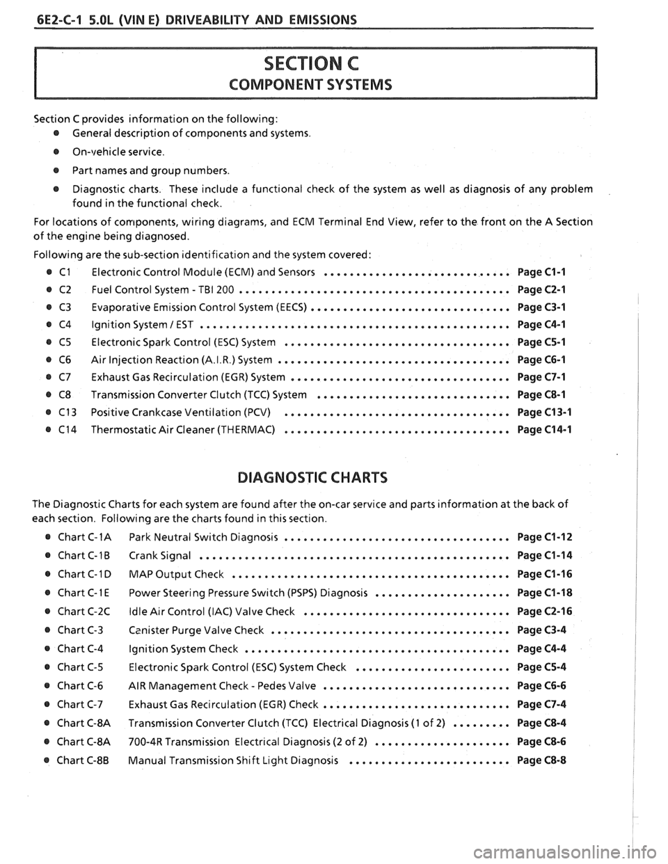
Section C provides information on the following:
@ General description of components and systems.
@ On-vehicle service.
@ Part names and group numbers.
@ Diagnostic charts. These include a functional check of the system as well as diagnosis of any problem
found in the functional check.
For locations of components, wiring diagrams, and ECM Terminal End View, refer to the front on the A Section
of the engine being diagnosed.
Following are the sub-section identification and the system covered:
@ C1 Electronic Control Module (ECM) and Sensors ............................. Page C1-1
@ C2 Fuel Control System - TBI 200 .......................................... Page C2-1
Evaporative Emission Control System (EECS) ...............................
Ignition System 1 EST ................................................
Electronic Spark Control (ESC) System ...................................
Air Injection Reaction (A.I.R.) System ....................................
Exhaust Gas Recirculation (EGR) System ..................................
Transmission Converter Clutch (TCC) System ..............................
Positive Crankcase Ventilation (PCV) ...................................
Thermostatic Air Cleaner (THERMAC) ...................................
BIAGNOSIIC CHARTS
Page C3-1
Page C4-1
Page C5-1
Page C6-1
Page C7-1
Page C8-1
Page C13-1
Page C14-1
The Diagnostic Charts for each system are found after the on-car service and parts information at the back of
each section. Following are the charts found in this section.
@ Chart C-1A Park Neutral Switch Diagnosis ................................... Page C1-12
@ Chart C-1B Crank Signal ................................................ Page C1-14
@ Chart C-1 D MAP Output Check ........................................ Page C1-16 I
..................... @ Chart C-1 E Power Steering Pressure Switch (PSPS) Diagnosis Page C1-18 1
................................ @ Chart C-2C Idle Air Control (IAC) Valve Check Page C2-16 !
..................................... @ Chart C-3 Canister Purge Valve Check Page C3-4 I
@ Chart C-4 Ignition System Check ......................................... Page C4-4
........................ @ Chart C-5 Electronic Spark Control (ESC) System Check Page C5-4
- ............................. @ Chart C-6 AIR Management Check Pedes Valve Page C6-6
............................. Chart C-7 Exhaust Gas Recirculation (EGR) Check Page C7-4
@ Chart C-8A Transmission Converter Clutch (TCC) Electrical Diagnosis (1 of 2) ......... Page C8-4 I
@ Chart C-8A 700-4R Transmission Electrical Diagnosis (2 of 2) ..................... Page C8-6 I
......................... @ Chart C-8B Manual Transmission Shift Light Diagnosis Page C8-8
Page 556 of 1825
DRIVEABILITY AND EMISSIONS 5.OL (VIN El 6EZ-C1-1
SECTION Cl
ELECTWONllC CONTROL MODULE (ECM) AND SENSORS
CONTENTS
GENERAL DESCRIPTION . . . . . . . . . . . . . . . C1-1 Coolant Temperature Sensor . . . . . . . . C1-5
ELECTRONIC CONTROL MODULE (ECM) . . C1-1 MAT Sensor. . . . . . . . . . . .. . . ... . . . . $1 -5
PROM ........................... C1-1 MAP Sensor. . . . . . . . . . . . . . . . . . . . . . C1 -6
CALPAK.........,................ C1-2 Oxygen (02) Sensor. . . . . . ... . . . a C1-6
ECM FUNCTION . . . , . . . . . . . . . . . . . . . . C1-2 Throttle Position Sensor (TPS) . . . . . . . . C1-6
INFORMATION SENSORS . . . . . . . . . . . . . C1-2 Vehicle Speed Sensor (VSS) . . . . . . . . . C1-6
Engine Coolant Temperature Sensor . . C1-2 PIN Switch. . . . . . . . . . . . . . . . . . . . . . . C1-6
MAP Sensor. . . . . . . . . . . . . . . . . . . . . . C1-2 (PSPS) . . . . . ... .. . . . ... . . .. .. . . . C1-6
MAT Sensor. . . . . . . . . . . . . . . . . . . . . . C1-3 AJC Request Signal . . . . . . . . . . . . . . . . C1-6
Oxygen (Oz) Sensor. . . . . . . . . .. . . . . . C1-3 Distributor Reference Signal . . . . . . . . . C1-6
Throttle Posit~on Sensor (TPS) . . . . . . . . C1-3 Knock Signal . . . . . . . . . . . . . . . . . . . C1-6
Knock Sensor . . . . . . . . . . . . . . . . . . . . C1-4 ON-CAR SERVICE . . . . . . . . . . . . . . . . . . . . . C1-6
Park Neutral Switch (Auto Only) . . . . . . C1-4 ELECTRONIC CONTROL MODULE . . . . . . . 61-6
Crank Signal . . . . . . , . . . . . . . . . . . . . . C1-4 PROM ........................... C1-7
A/C "On" Signal . . . , . . . . . . . . . . . . . . C1-4 Functional Check . . . . . . . . . . . . . . . . . C1-8
Vehicle Speed Sensor (VSS) . . . . . . . . . C1-4 CALPAK...................,...... C1-8
Distributor Reference Signal . . . . . . . . . C1-4 COOLANTSENSOR .. . . . . . . . , . . . . . . . . . C1-9
(PSPS) . . . . . . . . . . . . . . . . . . . . . . . . . C1-4 MAPSENSOR ..... ........ ... . .. . .* C1-9
DIAGNOSIS . . . . . . . . . . . . . . . . . . . . . . . . . C1-5 OXYGEN (02) SENSOR . . . . . . . . . a . . a . . C1-9
ECM ............................. C1-5 THROTTLE POSITION SENSOR (TPS) . . . . . C1-10
PROM ........................... C1-5 PARKINEUTRALSWITCH . . . . . . . . . . . . . . C1-10
ECM INPUTS.. . . . . . . . . . . . . . . . , . . . . . C1-5 PARTS
INFORMATION . . . . . . . . . . . . . . . . . C1-10
GENERAL DESCRIPTION
ELECTRONIC CONTROL MODULE (ECM)
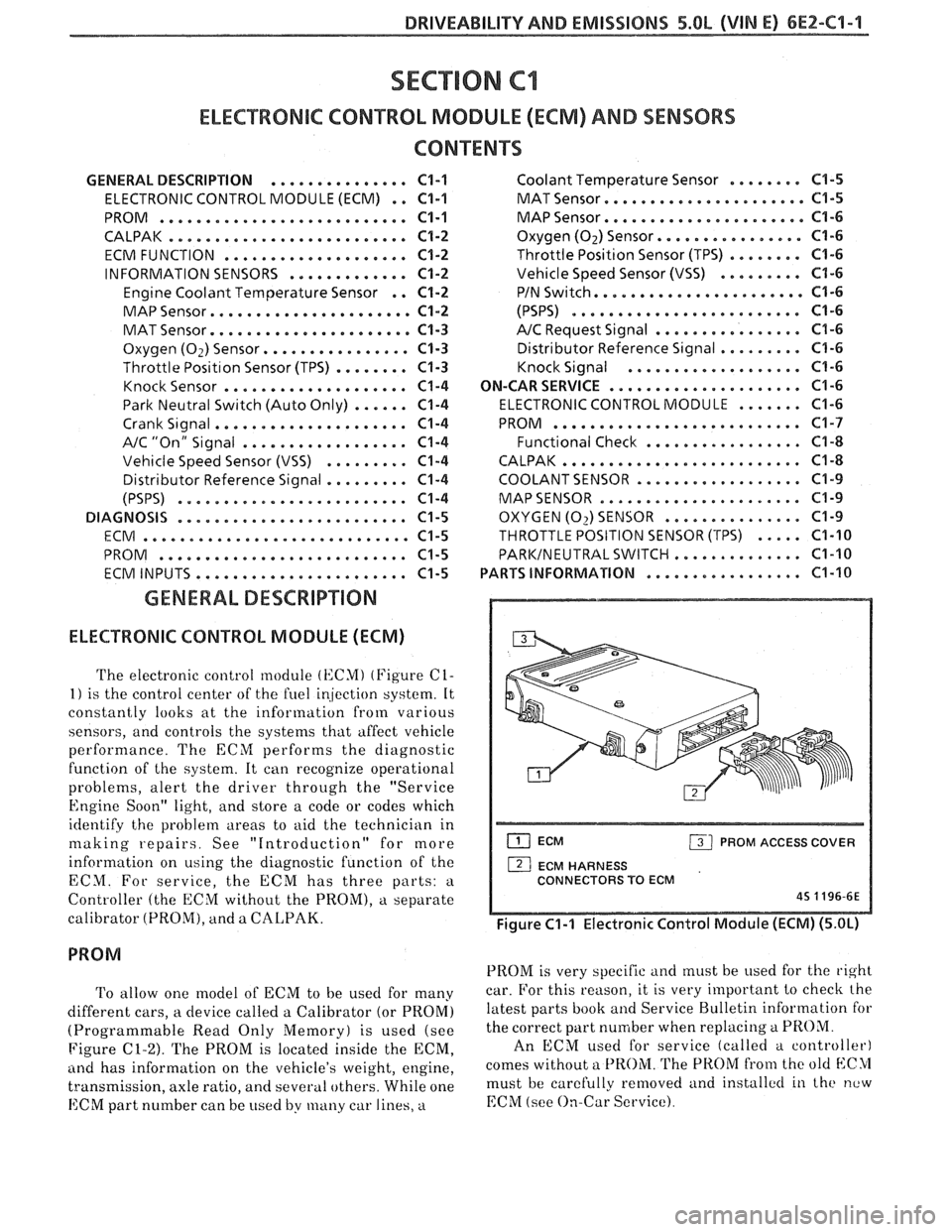
The electronic control module (KCMI (Figure C1-
1) is the control center of the fuel ir!jection system. It
constantly looks at the information from various
sensors, and controls the systems that affect vehicle
performance. The ECM performs the diagnostic
function of the system. It can recognize operational
problems, alert the driver through the "Service
Engine Soon" light, and store a code or codes which
identify the problem areas to aid the technician in
making repairs. See "Introduction" for more
information on using the diagnostic function of the
ECM. For service, the ECM has three parts:
a
Controller (the ECM without the PROM), a separate
calibrator (PROM), and a
CALPAK.
To allow one model of ECM to be used for many
different cars, a device called a Calibrator (or PROM)
(Programmable Read Only Memory) is used (see
Figure
C1-2). The PROM is located inside the ECM,
ancl has information on the vehicle's weight, engine,
transmission, axle ratio, and several others. While one
ECM part number can be used by many car lines, a
ECM PROM ACCESS COVER
1 ECM HARNESS
CONNECTORS TO ECM
45 1196-6E
Figure C1-1 Electronic Control Module (ECM) (5.OL)
PROM is very specific and must be used for the right
car. For this reason, it is very important to checlc the
latest parts book and Service Bulletin information for
the correct part number when replacing
a PROM.
An ECM used for service (called a controller)
comes without a
PROM. The PROM from the old blC>1
must be carefully removed and installctl in the new
EChI (see On-Car Service).
Page 557 of 1825
6EZ-C1-2 5.OL (VIN E) DRIVEABILITY AND EMISSIONS
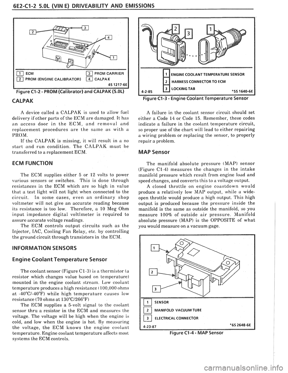
PROM CARRIER
PROM (ENGINE CALIBRATOR)
Figure C1-2 - PROM (Calibrator) and CALPAK (5.OL)
CALPAK
ENGINE COOLANT TEMPERATURE SENSOR
HARNESS CONNECTOR TO ECM
LOCKING TAB
4-2-85
*5S 1640-6E
Figure C1-3 - Engine Coolant Temperature Sensor
A device called a CALPAK is used to allow fuel
A failure in the coolant sensor circuit should set
delivery if other parts of the ECM are damaged. It has
either a Code 14 or Code 15. Remember, these codes
an access door in the ECM, and removal and
indicate a failure in the coolant temperature circuit,
replacement procedures are the
same as with a
so proper use of the chart will lead to either repairing
PRO;\/I. a wiring problem or replacing the sensor, to properly
If the CALPAK is missing, it will result in a no
repair a problem.
start
i111d run condition. The CALPAK must be
transferred to a replacement ECM.
MAP Sensor
ECM FUNCTION
The ECM supplies either 5 or 12 volts to power
various sensors or switches. This
is done through
resistances in the ECM which are so high in value
that a test light will not light when connected to the
circuit. In some cases, even an ordinary shop
voltmeter will not give an accurate reading because
its resistance is too low. Therefore, a 10 Meg Ohm
input impedance digital voltlmeter is required to
assure accurate voltage readings.
The ECM controls output circuits such as the
Injector, IAC, Cooling Fan Relay, etc. by controlling
the ground circuit through transistors in the ECM.
INFORMATION SENSORS
Engine Coolant Temperature Sensor
The coolant sensor (Figure C1-3) is a thermistor (a
resistor which changes value based on temperature)
mounted in the engine coolant stream.
[,ow coolant
temperature produces a high resistance
( 100,000 ohms
at
-40°C/-40°F) while high temperature causes low
resistance
(70 ohms at 13O0C/266"F)
The ECM supplies a 5-volt signal to the cooliint
sensor thru a resistor in the ECM and measures the
voltage. The voltage will be high when the engine is
cold,
and low when the engine is hot. By measuring
the voltage, the ECM knows the engine coolant
temperature. Engine coolant temperature affects most
systems the ECM controls. The
manifold absolute pressure
(MAP) sensor
(Figure
(21-4) measures the changes in the intake
manifold pressure which result from engine load and
speed changes, and converts this to a voltage output.
A closed throttle on engine coastdown would
produce a relatively low
MAP output, while a wide-
open throttle would produce a high output. This high
output is produced because the pressure inside the
manifold is the same as outside the manifold, so you
measure 100% of outside air pressure. Manifold
absolute pressure (MAP) is the OPPOSITE of what
you would measure on a vacuum gage.
SENSOR
MANIFOLD VACUUM TUBE
ELECTRICAL CONNECTOR
Figure C1-4 - MAP Sensor