suspension PONTIAC FIERO 1988 Service Owner's Manual
[x] Cancel search | Manufacturer: PONTIAC, Model Year: 1988, Model line: FIERO, Model: PONTIAC FIERO 1988Pages: 1825, PDF Size: 99.44 MB
Page 144 of 1825
STEERING, SUSPENSION, TIRES AND WHEELS DIAGNOSIS 3-19
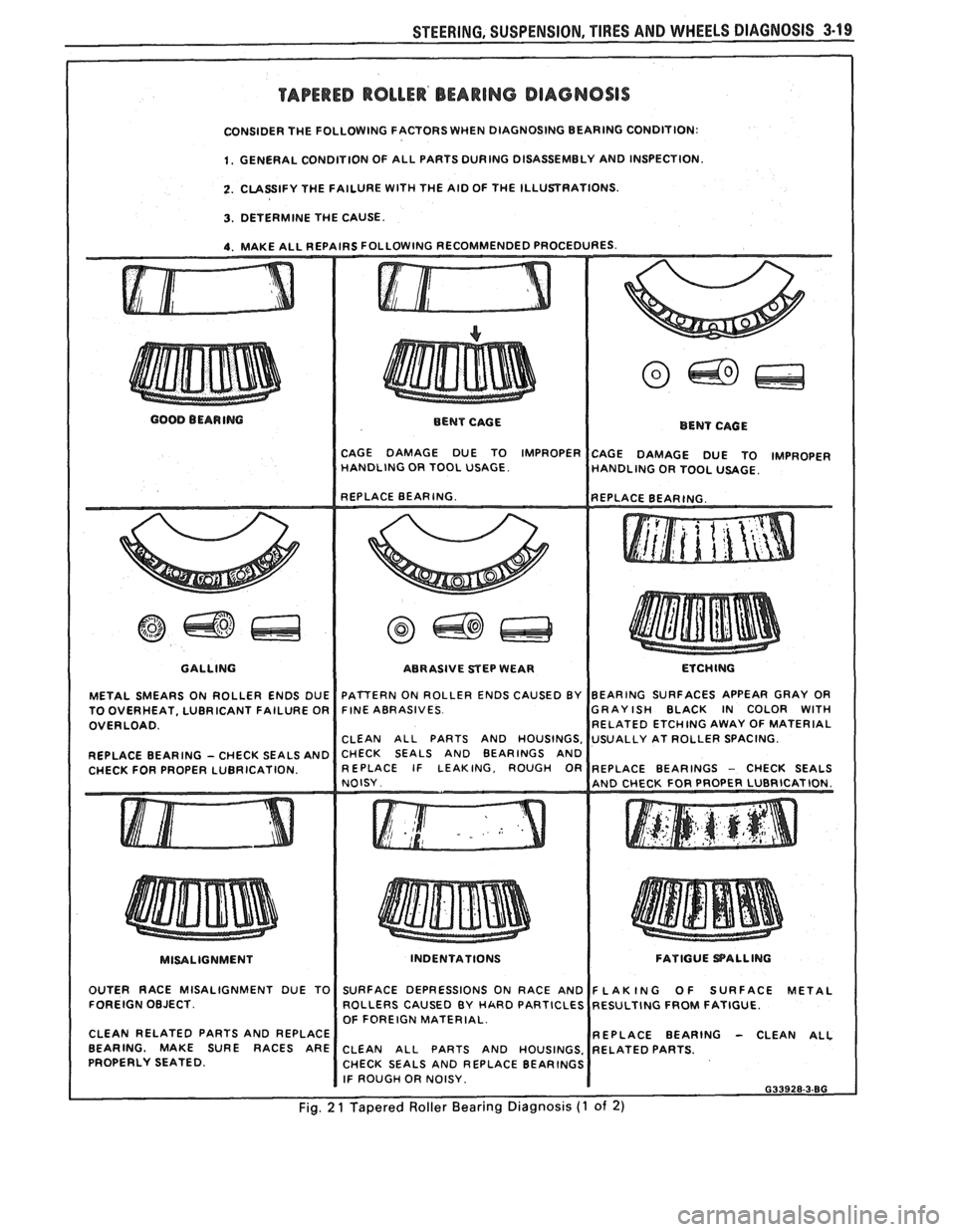
TAPERED ROLLER' BEARING DIAGNOSIS
CONSIDER THE FOLLOWING FACTORS WHEN DIAGNOSING BEARING CONDITION:
1. GENERAL CONDITION OF ALL PARTS DURING DISASSEMBLY AND INSPECTION.
2. CLASSIFY THE FAILURE WITH THE AID OF THE ILLUSTRATIONS.
3. DETERMINE THE CAUSE.
4. MAKE ALL REPAIRS FOLLOWING RECOMMENDED PROCEDURES.
GOOD BEARING
BENT CAGE
BENT CAGE
CAGE DAMAGE DUE TO IMPROPER
CAGE DAMAGE DUE TO )MPROPER HANDLING OR TOOL USAGE.
HANDLING OR TOOL USAGE.
GALLING
METAL SMEARS ON ROLLER ENDS DUE
TO OVERHEAT, LUBRICANT FAILURE OR
OVERLOAD.
REPLACE BEARING
- CHECK SEALS AND
CHECK FOR PROPER LUBRICATION. ABRASIVE
STEP WEAR
I ETCHING
FINE ABRASIVES GRAYISH BLACK IN COLOR
WITH RELATED ETCHING AWAY OF MATERIAL
CHECK SEALS AND BEARINGS AND
MISALIGNMENT
I
INDENTATIONS FATIGUE PALLING
OUTER RACE MISALIGNMENT DUE TO
FOREIGN OBJECT.
CLEAN RELATED PARTS AND REPLACE
BEARING. MAKE SURE RACES ARE
PROPERLY SEATED. SURFACE
DEPRESSIONS ON RACE AND
ROLLERS CAUSED BY
HARD PARTICLES
OF FOREIGN MATERIAL.
REPLACE BEARING
- CLEAN ALL CLEAN ALL PARTS AND HOUSINGS.
CHECK SEALS AND REPLACE BEARINGS
I IF ROUGH OR NOISY. I 633928.3-80
Fig. 2 1 Tapered Roller Bearing Diagnosis (1 of 2)
Page 146 of 1825
STEERING, SUSPENSION. TIRES AND WHEELS DIAGNOSIS 3-21
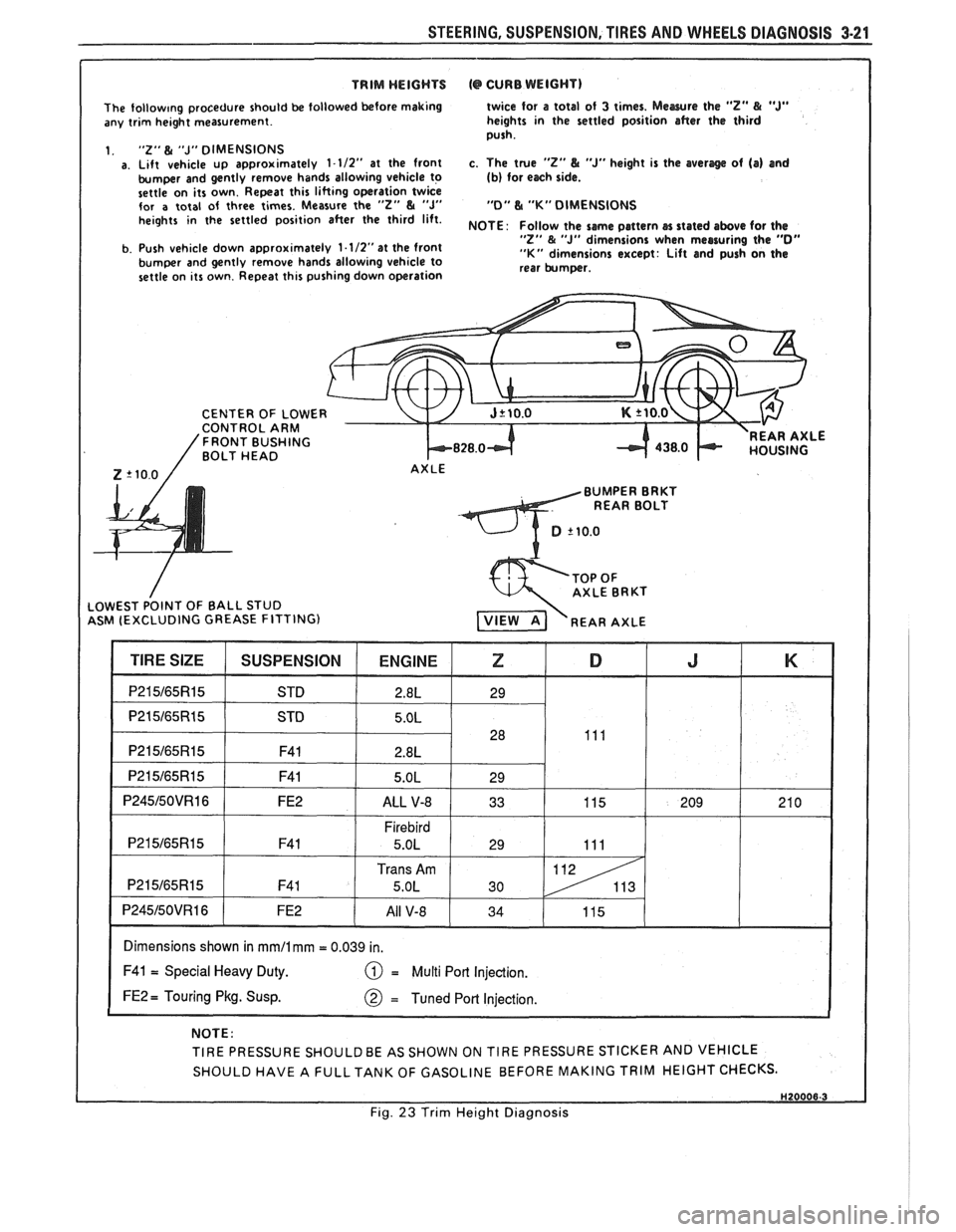
TRIM WEIGHTS (@ CURB WEIGHT) I
The follow~ng procedure should be followed before making
any trim height measurement.
1.
"2" & "J" DIMENSIONS a. Lift vehicle up approximately 1-112" at the front
bumper and gently remove hands allowing vehicle to
settle on its own. Repeat this lifting operation twice
for
a total of three times. Measure the "2" & "J" heights in the settled position after the third lift.
b. Push vehicle down approximately
1.1/2"at the front
bumper and gently remove hands allowing vehicle to
settle on its own. Repeat this pushing down operation twice for
a total
of 3 times. Mewre the "Z" & "J" heights in the settled position after the third
push.
c. The true
"2" L "J" height is the averlge of (a) and (b) for each side.
"0" L "K" DIMENSIONS
NOTE
: Follow the same pattern cn stated above for the "Z" & "J" dimensions when measuring the "0" "K" dimensions except: Lift and push on the
rear bumper.
CENTER OF
LOWE CONTROL ARM 'FRONT BUSHING BOLT HEAD k828.0-t REAR AXLE
Z '10.0 / AXLE
BUMPER BRKT
REAR BOLT
ASM (EXCLUDING GREASE FITTING)
I Dimensions shown in mmll mm = 0.039 in. I
F41 = Special Heavy Duty. = Multi Port Injection.
FE2 = Touring Pkg. Susp.
NOTE:
TIRE PRESSURE
SHOULDBE AS SHOWN ON TIRE PRESSURE STICKER AND VEHICLE
SHOULD HAVE A
FULLTANK OF GASOLINE BEFORE MAKING TRIM HEIGHT CHECKS.
I Fig. 23 Trim Height Diagnosis
Page 148 of 1825
-
WHEEL. ALIGNMENT 3A-1
SECTION 3A
WHEEL AL GNMENT
NOTICE: These fasteners are important attaching Do not use a replacement part of lesser quality or
parts, in that they could affect the performance of substitute
design. Torque values must be used as
vital components and systems, and/or could result specified during reassembly to assure proper
in major repair expense. They must be replaced retention of these parts. For prevailing torque
with one of the same part number or with an
nut(s) and bolt(s), refer to the "Reuse of Prevailing
equivalent part if replacement becomes necessary. torque
Nut(s) and Bolt(s)" chart in Section 0.
General Description ...................... .. ...... 3A- 1 On-Car Service ........................ .. ........... 3A-2
Caster .................... .. ............................ 3A- 1 Caster and Camber Adjustment .................. 3A-2
..................................... Camber ................... .. .............................. 3A-I Toe-In Adjustment 3A-2
Toe.. ................................................. 3A- 1 Axle Housing Alignment ......................... .... 3A-4
Preliminary Checks Prior to Specifications ....................... ... ............... 3A-4
Adjusting Alignment ..................... ...... 3A- 1
GENERAL DESCRIPmIOMI
Wheel alignment refers to the angular they tend to roll parallel on the road when the car is
relationship between the wheels, the suspension moving.
attaching parts and the ground.
PRELIMINARY CHECKS PRIOR TO ADJUSTING
CASTER ALIGNMENT
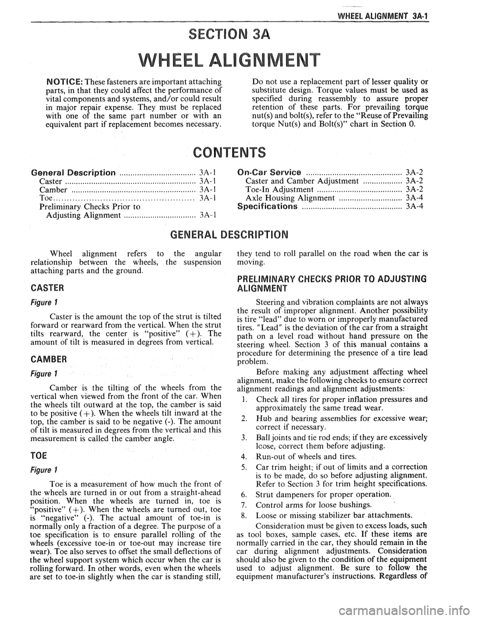
Figure 1
Caster is the amount the top of the strut is tilted
forward or rearward from the vertical. When the strut
tilts rearward, the center is "positive"
(+). The
amount of tilt is measured in degrees from vertical.
CAMBER
Figure 1
Camber is the tilting of the wheels from the
vertical when viewed from the front of the car. When
the wheels tilt outward at the top, the camber is said
to be positive
(+). When the wheels tilt inward at the
top, the camber is said to be negative
(-). The amount
of tilt is measured in degrees from the vertical and this
measurement is called the camber angle.
TOE
Figure i
Toe is a measurement of how much the front of
the wheels are turned in or out from a straight-ahead
position. When the wheels are turned in, toe is
"positive"
(+). When the wheels are turned out, toe
is "negative"
(-). The actual amount of toe-in is
normally only a fraction of a degree. The purpose of a
toe specification is to ensure parallel rolling of the
wheels (excessive toe-in or toe-out may increase tire
wear). Toe also serves to offset the small deflections of
the wheel support system which occur when the car is
rolling forward. In other words, even when the wheels
are set to toe-in slightly when the car is standing still, Steering
and vibration complaints are not always
the result of improper alignment. Another possibility
is tire "lead" due to worn or improperly manufactured
tires. "Lead" is the deviation of the car from a straight
path on a level road without hand pressure on the
steering wheel. Section
3 of this manual contains a
procedure for determining the presence of a tire lead
problem.
Before making any adjustment affecting wheel
alignment, make the following checks to ensure correct
alignment readings and alignment adjustments:
1. Check all tires for proper inflation pressures and
approximately the same tread wear.
2. Hub and bearing assemblies for excessive wear;
correct if necessary.
3. Ball joints and tie rod ends; if they are excessively
lcose, correct them before adjusting.
4. Run-out of wheels and tires.
5. Car trim height; if out of limits and a correction
is to be made, do so before adjusting alignment.
Refer to Section
3 for trim height specifications.
6. Strut dampeners for proper operation.
7. Control arms for loose bushings.
8. Loose or missing stabilizer bar attachments.
Consideration must be given to excess loads, such
as tool boxes, sample cases, etc. If these items are
normally carried in the car, they should remain in the
car during alignment adjustments. Consideration
should also be given to the condition of the equipment
used to adjust alignment. Be sure to follow the
equipment manufacturer's instructions. Regardless
of
Page 188 of 1825
STEERING LINKAGE 3B6-1
SECTION 3B6
STEERING LINKAGE
The following notice applies to one or more steps in the assembly
procedure of components in this portion of the manual as Notice indicated at
appropriate locations by the terminology "See Caution on Page
1 of this
Section
" .
NOTICE: These fasteners are important attaching parts in that they
could affect the performance of vital components and systems,
andlor could
result in major repair expense. They must be replaced with one of the same
part number or with an equivalent part if replacement becomes necessary. Do
not use a replacement part of lesser quality or substitute design. Torque
values must be used as specified during reassembly to assure proper retention
of these parts. For prevailing torque
nut(s) and bolt(s), refer to the "Reuse of
Prevailing Torque
Nut(s) and Bolt(s)" chart in Section 10.
CONTENTS
General Description ........................................... 3B6- 1 Relay Rod ............................................................ 3B6-3
Maintenance and Adjustments ............................... 3B6- I Idler Arm ............................................................. 3B6-4
On-Car Service ........................................................ 3B6-2 Pitman Arm ......................................................... 3B6-5
Tie Rods .............................................................. 3B6-2 Specifications ........................................................... 3B6-6
GENERAL DESCRIPTION
A parallelogram type steering linkage connects both
steering gear. The right end of the relay rod is supported by
front wheels to the steering gear through the
pitman arm,
the idler arm which pivots on a support attached to the
The right and left tie rods are attached to the steering arms
frame rail. The
pitman arm and idler arm remain parallel to
and to the relay rod by ball studs. The left end of the relay
each other while they move through symmetrical arcs. See
rod is supported by the
pitman arm, which is driven by the Fig. 3B6-2.
MAONTENANCE AND ADJUSTMENTS
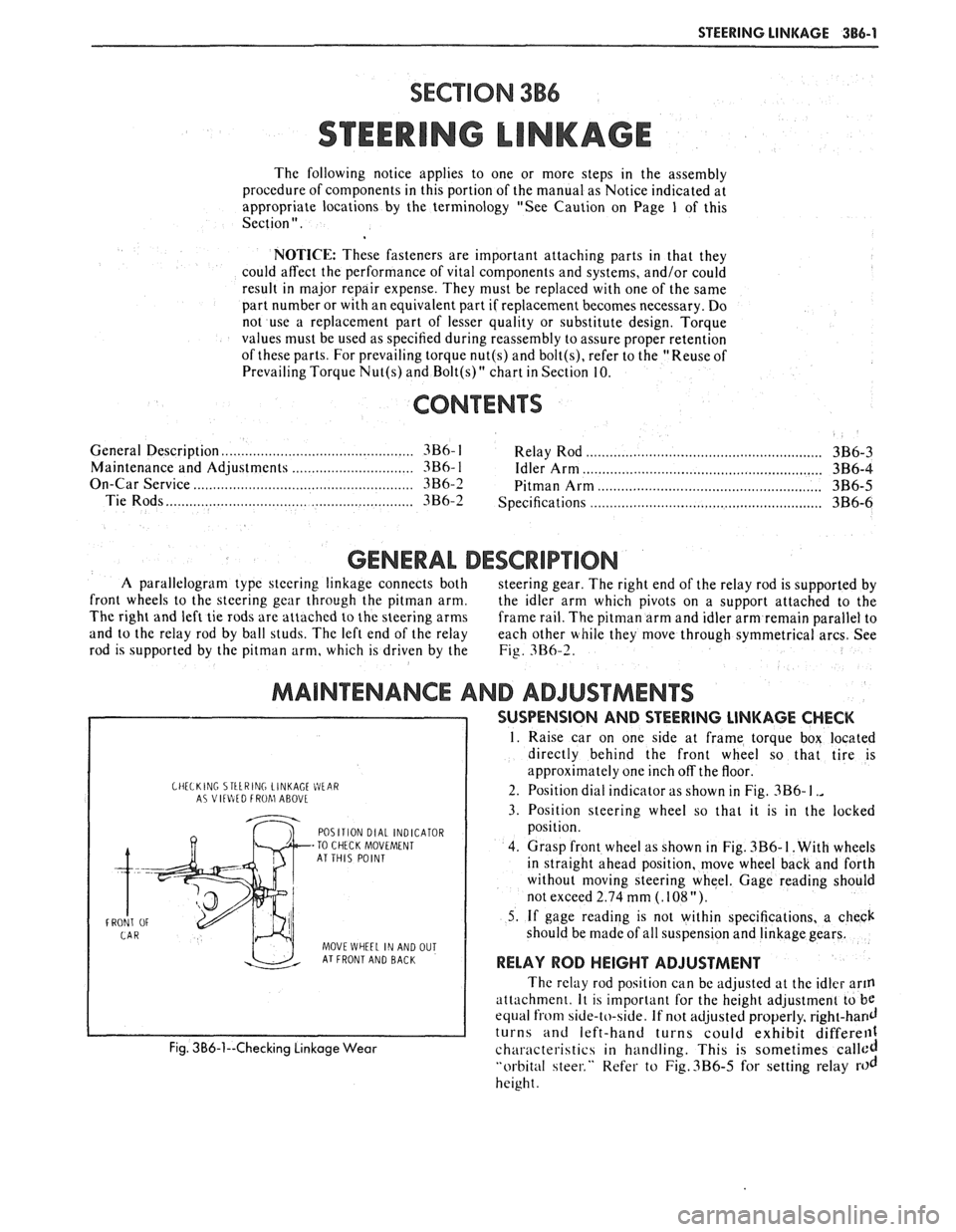
CHELKlNC STtLRING LINKAGE WEIR A? VltlItD FROhl ABOVL
POSITION DIAL INDICATOR
-TO CHECK MOVEMENT
AT THIS POINT
FRONT
OF
MOVE WHEEL IN AND OUT AT FRONT AND BACK
Fig. 3B6-1--Checking Linkage Wear
SUSPENSION AND STEERING LINKAGE CHECK
1. Raise car on one side at frame torque box located
directly behind the front wheel so that tire is
approximately one inch off the floor.
2. Position dial indicator as shown in Fig.
3B6- I .,
3. Position steering wheel so that it is in the locked
position.
4. Grasp front wheel as shown in Fig.
3B6- I. With wheels
in straight ahead position, move wheel back and forth
without moving steering wheel. Gage reading should
not exceed 2.74 mm
(. 108 ").
5. If gage reading is not within specifications, a check
should be made of all suspension and linkage gears.
RELAY ROD HEIGHT ADJUSTMENT
The relay rod position can be adjusted at the idler arm
attach men^. It is important for the height adjustment to be
equal from side-to-side. If not adjusted properly, right-hand
turns and left-hand turns could exhibit differell1
characteristics in handling. This is sometimes called
"orbital steer." Refer to Fig.3B6-5 for setting relay rod
height.
Page 192 of 1825
STEERING LINKAGE 386-5
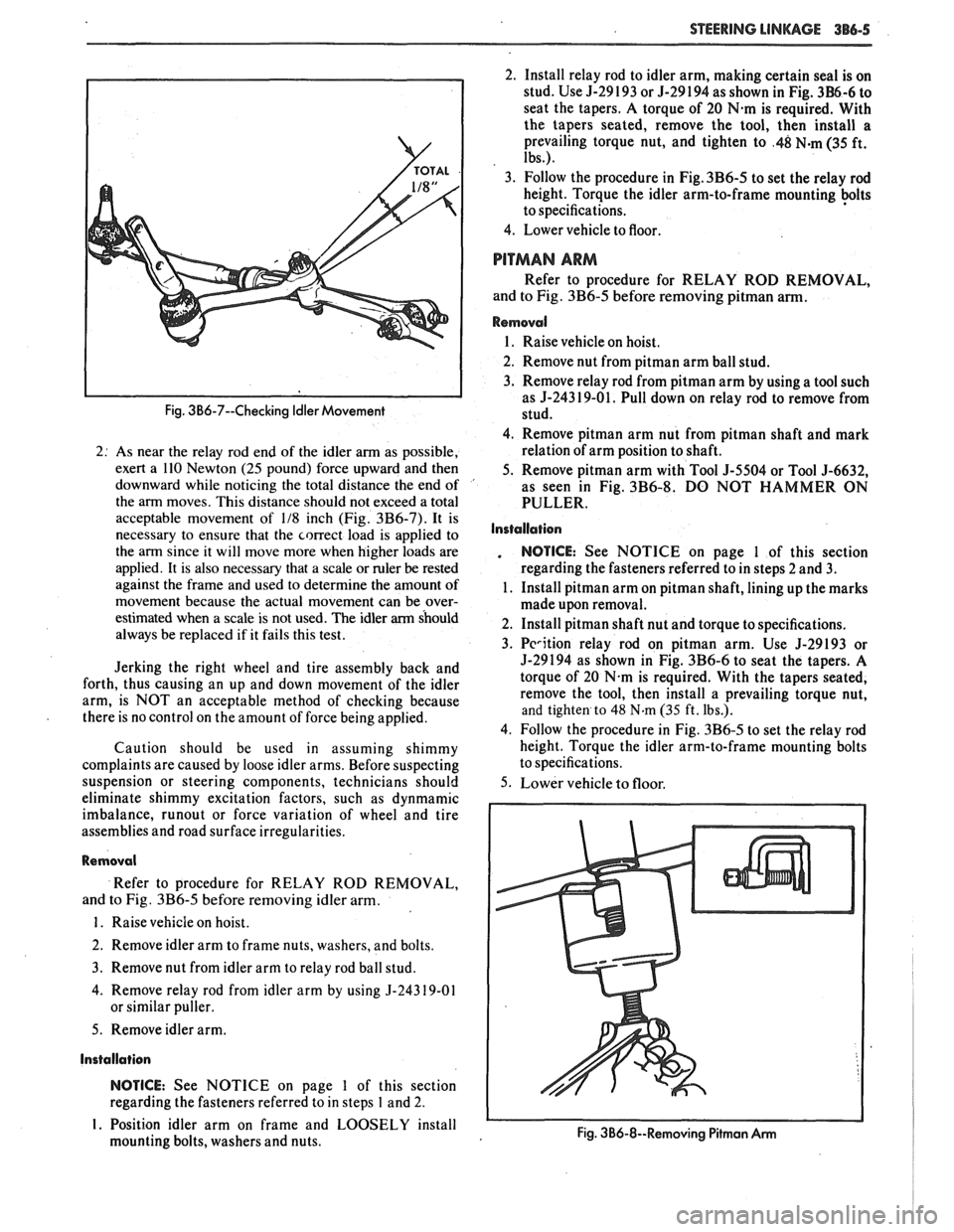
Fig. 3B6-7--Checking Idler Movement
2: As near the relay rod end of the idler arm as possible,
exert a 110 Newton
(25 pound) force upward and then
downward while noticing the total distance the end of '
the arm moves. This distance should not exceed a total
acceptable movement of
118 inch (Fig. 3B6-7). It is
necessary to ensure that the correct load is applied to
the arm since it will move more when higher loads are
applied. It is also necessary that a scale or ruler
be rested
against the frame and used to determine the amount of
movement because the actual movement can be over-
estimated when a scale is not used. The idler
arm should
always be replaced if it fails this test.
Jerking the right wheel and tire assembly back and
forth, thus causing an up and down movement of the idler
arm, is NOT an acceptable method of checking because
there is no control on the amount of force being applied.
Caution should be used in assuming shimmy
complaints are caused by loose idler arms. Before suspecting
suspension or steering components, technicians should
eliminate shimmy excitation factors, such as dynmamic
imbalance,
runout or force variation of wheel and tire
assemblies and road surface irregularities.
Removal
Refer to procedure for RELAY ROD REMOVAL,
and to Fig.
3B6-5 before removing idler arm.
1. Raise vehicle on hoist.
2. Remove idler arm to frame nuts, washers, and bolts.
3. Remove nut from idler arm to relay rod ball stud.
4. Remove relay rod from idler arm by using
5-24319-01
or similar puller.
5. Remove idler arm.
Installation
NOTICE: See NOTICE on page 1 of this section
regarding the fasteners referred to in steps
1 and 2.
I. Position idler arm on frame and LOOSELY install
mounting bolts, washers and nuts. 2.
Install relay rod to idler arm, making certain seal is on
stud. Use 5-29 193 or 5-29 194 as shown in Fig.
3B6-6 to
seat the tapers. A torque of 20
N.m is required. With
the tapers seated, remove the tool, then install a
prevailing torque nut, and tighten to
.48 N-m (35 ft.
Ibs.).
3. Follow the procedure in Fig. 3B6-5 to set the relay rod
height. Torque the idler arm-to-frame mounting
+Its
to specifications.
4. Lower vehicle to floor.
PITMAN ARM
Refer to procedure for RELAY ROD REMOVAL,
and to Fig.
3B6-5 before removing pitman arm.
Removal
1. Raise vehicle on hoist.
2. Remove nut from
pitman arm ball stud.
3. Remove relay rod from pitman arm by using a tool such
as
5-243 19-01. Pull down on relay rod to remove from
stud.
4. Remove pitman arm nut from pitman shaft and mark
relation of arm position to shaft.
5. Remove
pitman arm with Tool 5-5504 or Tool 5-6632,
as seen in Fig.
3B6-8. DO NOT HAMMER ON
PULLER.
Installation
. NOTICE: See NOTICE on page 1 of this section
regarding the fasteners referred to in steps 2 and
3.
1. Install pitman arm on pitman shaft, lining up the marks
made upon removal.
2. Install pitman shaft nut and torque to specifications.
3.
Pcrition relay rod on pitman arm. Use 5-29193 or
5-29194 as shown in Fig. 3B6-6 to seat the tapers. A
torque of 20
N.m is required. With the tapers seated,
remove the tool, then install a prevailing torque nut,
and tighten to 48 N.m (35 ft. Ibs.).
4. Follow the procedure in Fig.
3B6-5 to set the relay rod
height. Torque the idler arm-to-frame mounting bolts
to specifications.
5. Lower vehicle to floor.
Fig. 3B6-8--Removing Pitmon Arm I I
Page 212 of 1825
FRONT SUSPENSION 3C-1
SEC"T0RI 3C
FRONT SUSPENS
NOTICE: All front suspension fasteners are an important attaching part in that it could affect the
performance of vital parts and systems, and/or could result in major repair expense. They must be replaced with
one of the same part number or with an equivalent part if replacement becomes necessary. Do not use a
replacement part of lesser quality or substitute design. Torque values must be used as specified during reassembly
to assure proper retention of this part.
NOTICE: Never attempt to heat, quench or straighten any front suspension part. Replace it with a new part
or
damage to the part may result.
CONTENTS
General lnformation ....................................................................................................... 3C-I
On-Car Service ................................................................................................................... 3C- I
Specifications ..................................................................................................................... 3C- 10
GENERAL INFORMATION
The front suspension is designed to allow each
wheel to compensate for changes in the road surface ON-CAR SERVICE
level without appreciably affecting the opposite wheel. WHEEL BEARINGS
Each wheel is independently connected to the frame by
The proper functioning of the front suspension
a steering
kunckle, strut assembly, ball joint, and lower cannot be maintained unless the front wheel tapered arm. The steering in a roller bearings are correctly adjusted. The bearings
prescribed three dimensional arc. The front wheels are
must be a slip fit on the spindle and the inside diameter held in proper relationship to each other by two tie rods of the bearings should be lubricated to insure proper which are connected to steering arms on the knuckles ~h~ spindle nut must be a free-running fit and to the relay rod assembly.
on the threads.
Coil chassis springs are mounted between the
spring housings on the front crossmember and the
lower control arms. Ride control is provided by double,
direct acting strut assemblies. The upper portion of
each strut assembly extends through the fender well
and attaches to the upper mount assembly with a nut.
Side roll of the front suspension is controlled by
a spring steel stabilizer shaft. It is mounted in rubber
bushings which are held to the frame side rails by
brackets. The ends of the stabilizer are connected to the
lower control arms by link bolts and are isolated by
rubber grommets.
The inner ends of the lower control arms have
pressed in bushings. Bolts (passing through the
bushings) attach the arm to the suspension
crossmember. The lower ball joint assembly is a press
fit in the arm and attaches to the steering knuckle with
a torque prevailing nut.
Rubber grease seals are provided at ball socket
assemblies to keep dirt and moisture from entering the
joint and damaging bearing surfaces.
Adjustment
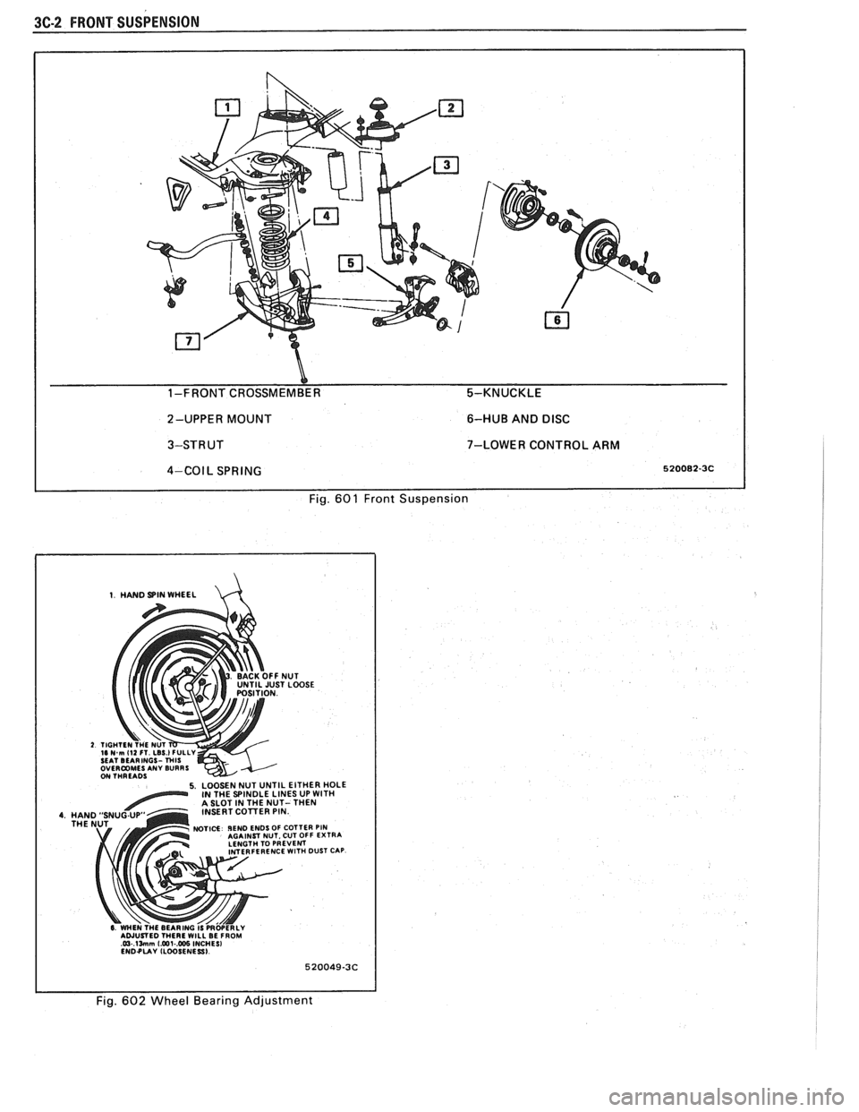
Figure 602
NOTICE: See NOTICE on Page 3C-1
of this
section.
1. Remove dust cap from hub.
2. Remove cotter pin from spindle and spindle nut.
3. Tighten the spindle nut to 16 Nsm (12 lb. ft.)
while turning the wheel assembly forward by
hand to fully seat the bearings. This will remove
any grease or burrs which could cause excessive
wheel bearing play later.
4. Back off the nut to the "just loose" position.
5. Hand tighten the spindle nut. Loosen spindle nut
until either hole in the spindle lines up with a slot
in the nut. Not
nlore than 1/2 flat.
6. Install
new cotter pin. Bend the ends of the cotter
pin against nut, cut off extra length to ensure ends
will not interfere with the dust cap.
7. Measure the looseness in the hub assembly. There
will be
from .03 to . l3mm (.001 to .005 inches)
end play when properly adjusted.
8. Install dust cap on hub.
FRONT SUSPENSION
Refer to Fig. 610 for illustration of attachment
provisions for the bolted-on front suspension
suspension
crossmember.
Page 213 of 1825
3C-2 FRONT SUSPENSION
Y 1-FRONT CROSSMEMBER 5-KNUCKLE
2-UPPER MOUNT 6-HUB
AND
DISC
3-STRUT 7-LOWER CONTROL ARM I
4-COIL SPRING 520082-3C I I Fig. 601 Front Suspension
1. HAND SPIN WHEEL d
NUT iT LOOSE
5. LOOSEN NUT UNTIL EITHER HOLE IN THE SPINDLE LINES UP WlTH A SLOT IN THE NUT- THEN
INSERT COlTER PIN
NOTICE IEND ENDS OF COTTER PIN AGAINST NUT. CUT OFF EXTRA
LENGTH TO PREVENT
FERENCE
WlTH DUST CAP
6 WHEN THE BEARING IS PRWERLY AWUSTED THERE WILL BE FROM @.lMm [email protected] INCHES1 ENDPUY ILWSENESSI
1 I Fig. 602 Wheel Bearing Adjustment
Page 214 of 1825
FRONT SUSPENSION 3C3
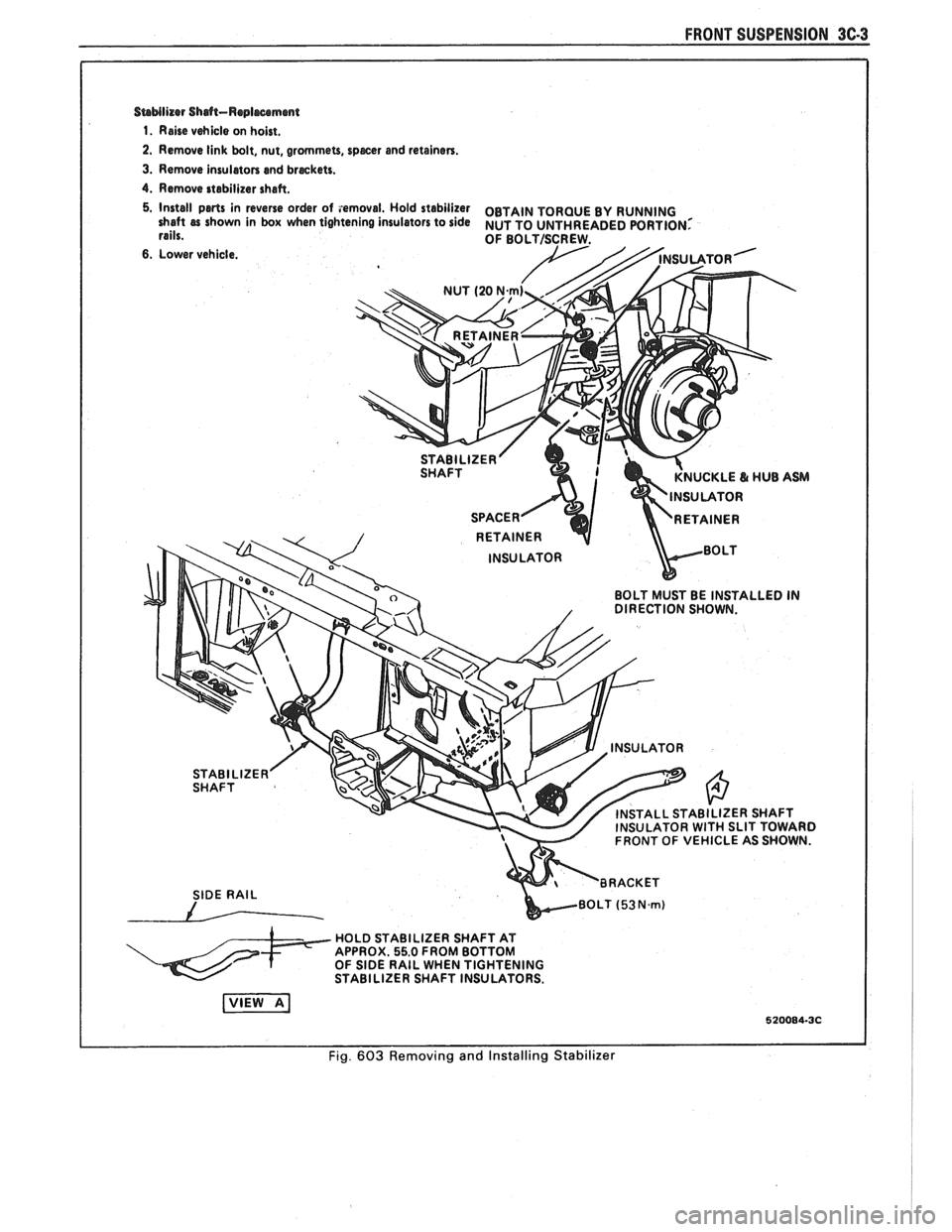
SaMlizer Sh&-Replrcrmmt
1. Rehe vehicle on hoist.
2. Remove link bolt, nut, grommets, specer and retainers.
3. Remove insulators end breckets.
4. Remove stabilizer shaft.
5.
Install ports in reverse order of iemova!. Hold stabilizer OBTAIN TORQUE BY RUNNING shaft as shown in box when tighten~ng ~nsulators to s~de NUT TO UNTHREADED PORTION: rails. OF BOLTISCREW.
6. Lower vehicle.
NUCKLE
6r HUB AW
SHAFT L STABILIZER SHAFT
TOR
WITH SLIT TOWARD
OF VEHICLE AS SHOWN.
SlDE RAIL
A
HOLD STABILIZER SHAFT AT
APPROX. 55.0 FROM BOTTOM
OF SlDE RAlL WHEN TIGHTENING
STABILIZER SHAFT INSULATORS.
I Fig. 603 Removing and Installing Stabilizer I
~
Page 215 of 1825
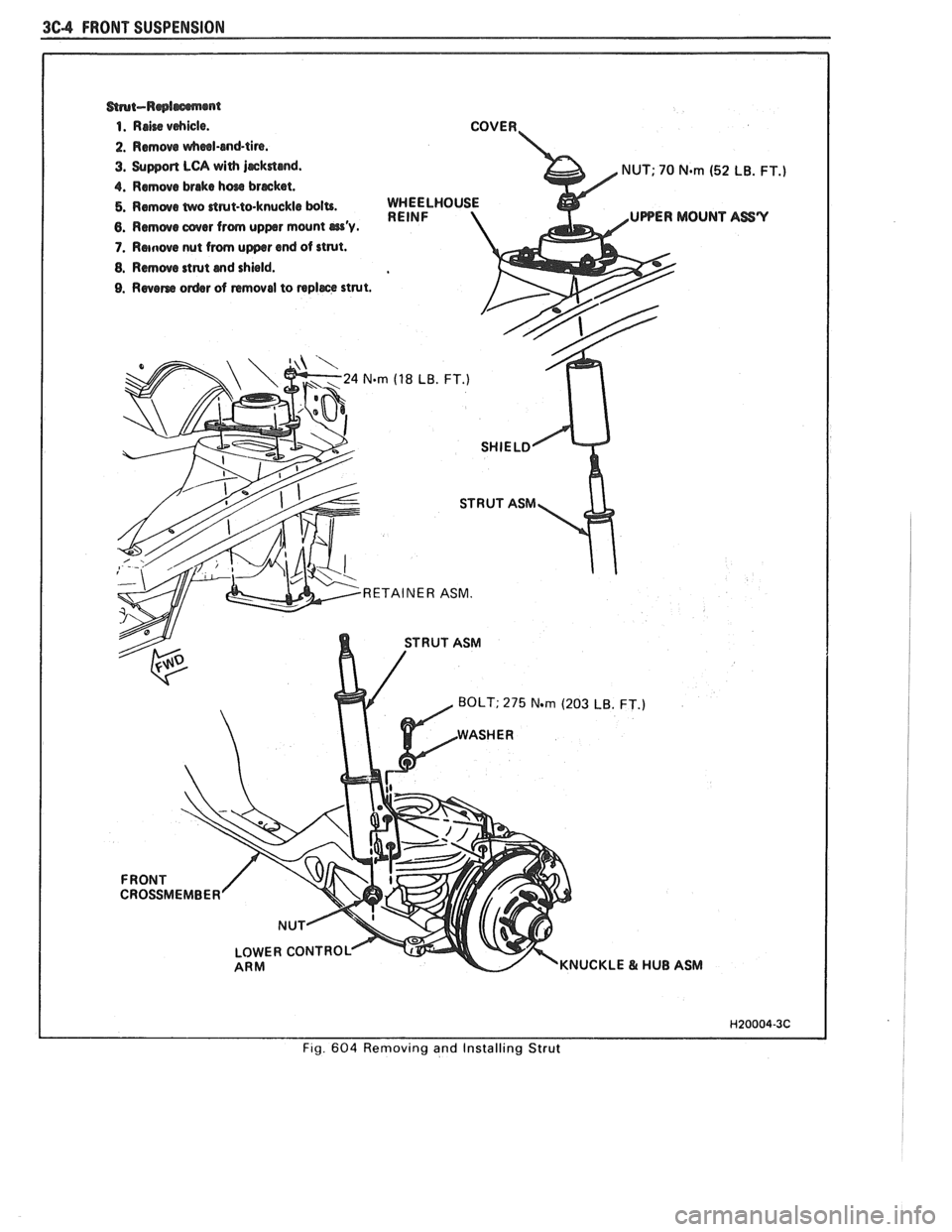
3C-4 FRONT SUSPENSION
3. Support LCA with j~kdmd. NUT; 70 Nern (52 LB. FT.)
4.
Remove brake hw brscket.
5. Remove tnro drut-to-knuckle bolts.
6. Remove cover from upper mount w'y. UPPER MOUNT ASS'V
7. Rmnove nut from upper end of strut.
8. Remove strut snd shield.
9. Revem order of removal to replece strut.
RETAINER ASM.
BOLT; 275 N.rn (203 LB. FT.)
CROSSMEMBER
LOWER CONTROL
KNUCKLE & HUB ASM
Fig. 604 Removing and Installing Strut I
Page 216 of 1825
FRONT SUSPENSION 3C-5
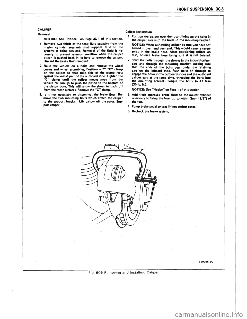
CALIPER
Remowd
NOTICE: See "Notice" on Page 3C-1 of this section.
1. Remove two thirds of the total fluid capecity from the meter cylinder reservoir that supplies fluid to the rystemrls) baing ~~iCed. Removal of the fluid is ne-
cessary to prevent nservoir overflow when the caliper
piston is pushed back in its bore to remove the caliper. Dircard the.brake fluid removed.
2. Raise the vehicle on a hoist and rumove (he wheel
covers and wheel assemblies, Position a 7" "C" clamp
on the caliper ro that solid side of the clamp resu against the metal part of the outboard shoe. Tighten the "C" clamp until the caliper mwes away from the vehicle far enough to push the piston to the bottom of
the piston bore. This will allow the shoes to back off
from the
rotcr surfaces. Remove the "C" clamp.
Mipr Installation
1. Position the caliper over the rotor, lining up the holes in
the caliper can with the holes in (he mounting brmket.
NOTICE: When rsinrtalling calipsr bc sure you hwe not
turned it over, end over end. This would cause s even twist in the brake hose. After poritioning caliper on dirc, observe brake hose being sun it is not twisted.
2. Start (he bolts through the rlmves in the inboard caliper ears and through the mounting brmket, making sure
that the ends of the bolts pars under (he rstaining esn on the inboard ohm. Push bolts on through to
engage the holes in the outboard rhm and the outboard
caliper ears at the same time, thmrding the bolts into
the mounting brwket. Torque the bolts to 47 N-m (35 Ib. tt.).
NOTICE: See "Notice" on Psge 1 of this section.
3. It
is not necessary to disconnect the brake lines. Re-
3. Add fresh approved brake fluid to the master cylinder
rnwe the two mounting bolts which attach the caliper
reservoirs to bring the level up to within 3mm [I/&') ot
to the support bracket. Lift caliper off the rotor. Sup.
the top.
port caliper.
4. Pump brake pedal to seat linings
wainst rotor.
5. Recheck the brake system.
I I
FI~ 605 Ren~ov~ng and Iristalltrig Callper