key battery PONTIAC FIERO 1988 Service Repair Manual
[x] Cancel search | Manufacturer: PONTIAC, Model Year: 1988, Model line: FIERO, Model: PONTIAC FIERO 1988Pages: 1825, PDF Size: 99.44 MB
Page 160 of 1825
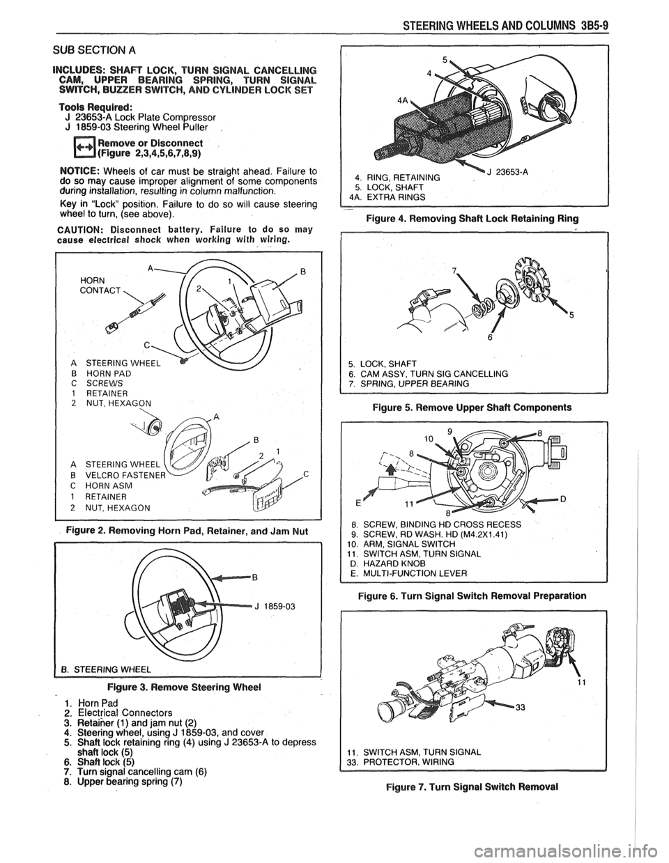
STEERING WHEELS AND COLUMNS 385-9
SUB SECTION A
INCLUDES: SHAR LOCK, TURN SIGNAL CANCELLING
CAM, UPPER BEARING SPRING, TURN SIGNAL
SWITCH,
BULZER SWITCH, AND CYLINDER LOCK SET
Tools Required:
J 23653-A Lock Plate Compressor
J 1859-03 Steering Wheel Puller
Remove or Disconnect
(Figure
2,3,4,5,6,7,8,9)
4 RING, RETAINING 5 LOCK, SHAFT
NOTICE: Wheels of car must be straight ahead. Failure to
do so may cause improper alignment of some components
during installation, resulting in column malfunction.
Key in "Lock position. Failure to do so will cause steering
- wheel to turn, (see above).
Figure 4. Removing Shaft Lock Retaining Ring
CAUTION: Disconnect battery. Failure to do so may
cause electrical
shock when working with wiring.
B HORN PAD
C SCREWS
1 RETAINER 2 NUT, HEXAGON
A STEERING WHEEL
B VELCRO FASTENE
C HORNASM
Figure 2. Removing Horn Pad, Retainer, and Jam Nut Figure
5. Remove Upper Shaft Components
8 SCREW,
BINDING HD CROSS RECESS 9. SCREW, RD WASH. HD (M4.2X1.41)
10 ARM, SIGNAL SWITCH
11 SWITCH ASM, TURN SIGNAL
D HAZARD KNOB
Figure 6. Turn Signal Switch Removal Preparation
Figure
3. Remove Steering Wheel
1. Horn Pad
2. Electrical Connectors 3. Retaiher (1) and jam nut (2) 4. Steering wheel, using J 1859-03, and cover 5. Shait lock retaining ring (4) using J 23653-A to depress
shaft lock (5)
6. Shaft lock (5) 7. Turn signal cancelling cam (6) 8. Upper bearing spring (7) Figure 7. Turn Signal Switch Removal
Page 166 of 1825
SUB SECTION A
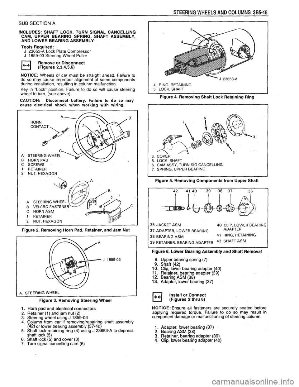
INCLUDES: SHAFT LOCK, TURN SIGNAL CANCELLING
CAM, UPPER BEARING SPRING, SHAFT ASSEMBLY,
AND LOWER BEARING ASSEMBLY
Tools Required:
J 23653-A Lock Plate Compressor J 1859-03 Steering Wheel Puller
Remove or Disconnect
(Figures
2,3,4,5,6)
NOTICE: Wheels of car must be straight ahead. Failure to
do so may cause improper alignment of some components
during installation, resulting in
colunin malfunction.
Key in "Lock" position. Failure to do so
wi!l cause steering
wheel to turn, (see above).
CAUTION: Disconnect battery. Failure to do so may
cause electrical shock when working with wiring.
HORN
C
STEERING WHEEL
HORN PAD
I
C SCREWS
1 RETAINER
2 NUT, HEXAGON
A STEERING WHEEL
B VELCRO
FASTENEF v C HORNASM
1 RETAINER
2 NUTSHEXAGON
Figure 2. Removing Horn Pad, Retainer, and Jam Nut
Figure
3. Removing Steering Wheel
1. Horn pad and electrical connectors
2. Retainer (1) and jam nut (2)
3. Steering wheel using J 1859-03 4. Column from car if removingirepairing shaft assembly
(42) or lower bearing assembly (37-40)
5. Shaft lock retaining ring (4) using
J 23653-A to depress
shaft lock (5)
6. Shaft lock (5) and cover (3)
7. Turn signal cancelling cam (6)
STEERING WHEELS AND COLUMNS 385-15
I
4. RING, RETAINING 5. LOCK. SHAFT
Figure 4. Removing Shaft Lock Retainingain;
SY. TURN SIG CANCELLING , UPPER BEARING
Figure 5. Removing Components from Upper Shaft
36 JACKET ASM
40 CLIP, LOWER BEARING
37 ADAPTER, LOWER BEARING ADAPTER
38 BEARING
ASM 41
RING, RETAINING 42 SHAFT ASM
Figure 6. Lower Bearing Assembly and Shaft Removal
Upper bearing spring
(7) Shaft (42)
Clip, lower bearing adapter (40)
Retainer, bearing adapter
(39) Bearing ASM (38) Adapter, lower bearing (37)
Install or Connect
(Figures
2 thru 6)
NOTICE: Ensure all fasteners are securely seated before
applying required torque. Failure to do so may result in
component damage or malfunctioning of steering column.
1. Adapter, lower bearing (37) 2. Bearing ASM (38)
3. Retainer, bearing adapter (39)
4. Clip, lower bearing adapter (40)
Page 172 of 1825
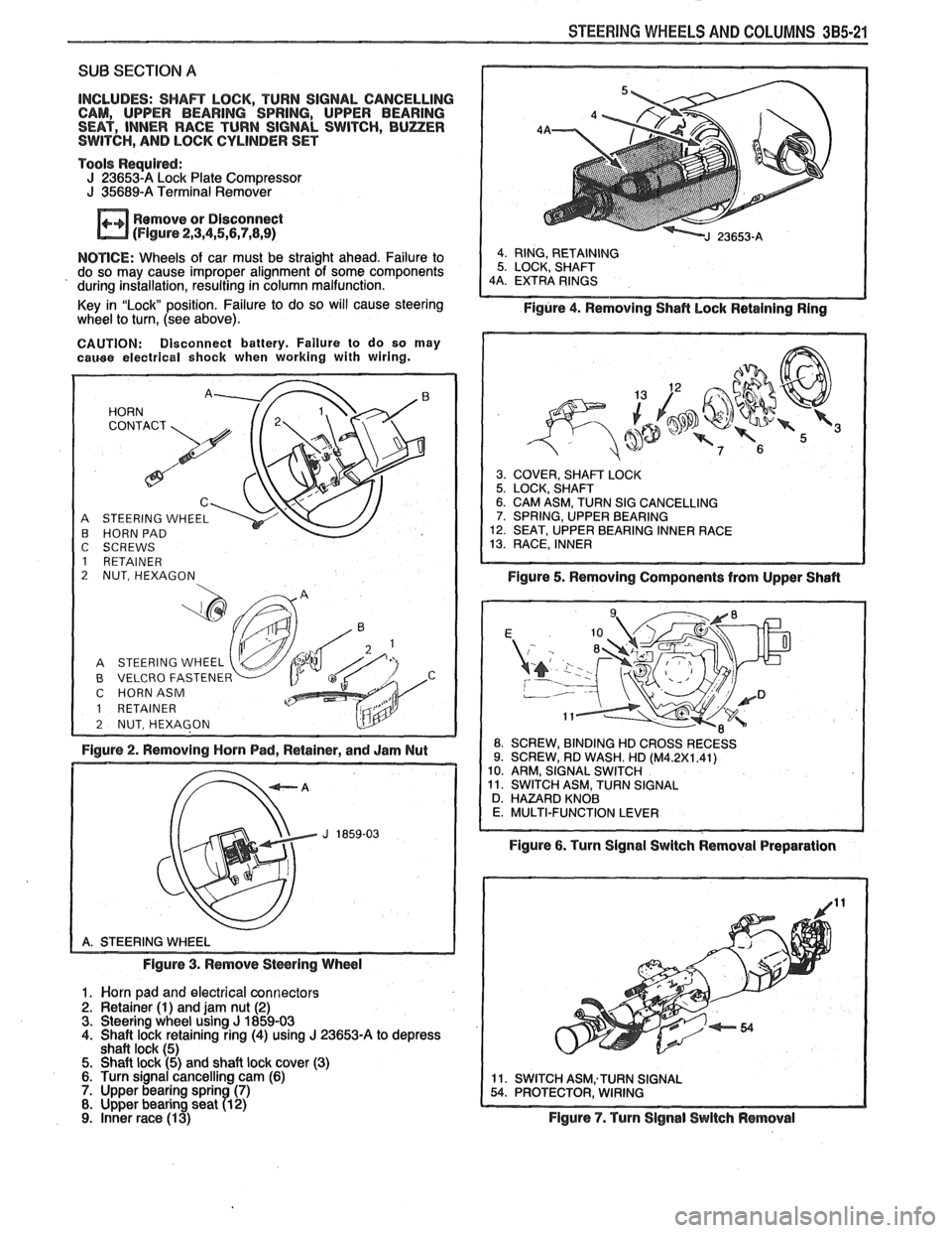
STEERING WHEELS AND COLUMNS 385-21
SUB SECTION A
INCLUDES: SHAR LOCK, TURN SIGNAL CANCELLING
CAM, UPPER BEARING SPRING, UPPER BEARING
SEAT, INNER RACE TURN SIGNAL SWITCH,
BUZER SWITCH, AND LOCK CYLINDER SET
Tools
Requird: J 236534 Lock Plate Compressor J 35689-A Terminal Remover
Remove or Disconnect
(Flgure 2,3,4,5,5,7,8,9)
NOTICE: Wheels of car must be straight ahead. Failure to
do so may cause improper alignment of some components
' during installation, resulting in column malfunction.
Key in "Lock" position. Failure to do so will cause steering
wheel
to turn, (see above).
CAUTION: Disconnect battery. Failure to do so may cauee electrical shock when working with wiring.
A STEERING WHEEL B HORN PAD
C SCREWS
1 RETAINER
2 NUT, HEXAGON
B VELCRO FASTENER C HORNASM
1 RETAINER
Figure 2. Removing Horn Pad, Retainer, and Jam Nut
Figure 3. Remove
Stwring Wheel
1. Worn pad and electrical connectors 2. Retainer (1) and jam nut (2) 3. Steering wheel using J 1859-03 4. Shaft lock retaining ring (4) using J 23653-A to depress
shaft lock (5) 5. Shaft lock (5) and shaft lock cover (3) 6. Turn signal cancelling cam (6) 7. Upper bearing sprin (7) 8. Upper bearing seat 71 2)
9. inner race (1 3)
Figure 4. Removing Shafl hock Retaining Ring
3. COVER, SHAFT LOCK 5. LOCK, SHAFT 6. CAM ASM, TURN SIG CANCELLING 7. SPRING, UPPER BEARING 12. SEAT, UPPER BEARING INNER RACE 13. RACE, INNER
Figure 5. Removing Components from Upper Shafl
ROSSRECESS
Figure 6. Turn Signal Swltch Removal Preparation
Figure
7. Turn Signal Switch Removal
Page 180 of 1825
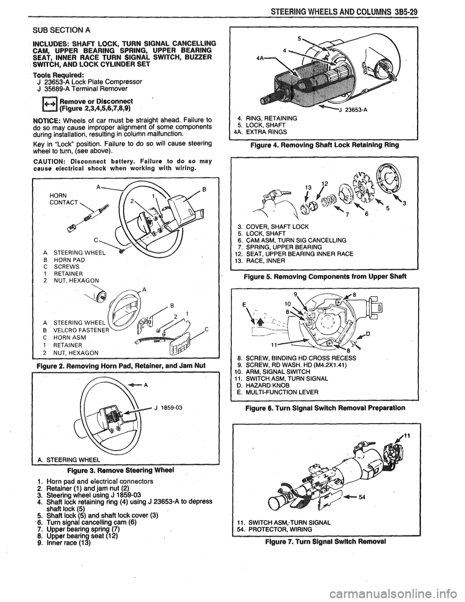
STEERING WHEELS AND COLUMNS 3B5-29
SUB SECTION A
INCLUDES: SHAm LOCK, TURN SIGNAL CANCELLlNG CAM, UPPER BEARING SPRING, UPPER BEARING
SEAT, INNER RACE TURN SIGNAL SWITCH, BUZZER
SWITCH,
AND LOCK CYLINDER SET
Tools
Requird: J 23653-A Lock Plate Compressor J 35689-A Terminal Remover
Remove or Disconnect
(Figure
,2,3,4,5,6,7,8,9)
NOTICE: Wheels of car must be straight ahead. Failure to
do so may cause improper alignment of some components
during installation, resulting in column malfunction.
Key in
"Lock position. Failure to do so will cause steering
wheel to turn, (see above).
CAUTION: Disconnect battery. Failure to do so may
cause electrical shock when working with wiring.
HORN '. 72' CONTACT
A STEERING WHEEL
B HORN PAD C SCREWS 1 RETAINER 2 NUT, HEXAGON
A STEERING WHEEL
B VELCRO FASTENER C HORNASM
1 RETAINER
2 NUT, HEXAGON L!lY -
Figure 2. Removing Horn Pad, Retainer, and Jam Nut
Figure 3. Remove
Stwring Wheel
1. Horn pad and electrical connectors
2. Retainer (1) and jam nut (2) 3. Steering wheel using J 1859-03
4. Shaft lock retaining ring (4) using J 23653-A to depress
shaft lock (5)
5. Shaft lock (5) and shaft lock cover (3)
6. Turn signal cancelling cam (6)
7. Upper bearing sprin (7) 8. Upper bearing seat R 2) 9. Inner race (13)
4. RING, RETAINING
5. LOCK, SHAFT
4A. EXTRA RINGS
Figure 4. Removing Shafl Lock Retaining Ring
3. COVER, SHAm LOCK 5. LOCK, SHAFT 6. CAM ASM, TURN SIG CANCELLING 7. SPRING, UPPER BEARING
12. SEAT, UPPER BEARING INNER RACE
13. RACE, INNER
Figure 5. Removing Components from Upper Shan
Figure 6. Turn Signal Swltch Removal Preparation
11. SWITCH ASM;TURN SIGNAL 54. PROTECTOR, WIRING
Flgure 7. Turn Signal Switch Removal
Page 365 of 1825
BA2-14 2.8 LITER V-6
bores for oversize valves use tool 5-5330-1, 2 or 3,
respectively.
VALVE SEATS
Reconditioning the valve seats is very important,
because the seating of the valves must be perfect for the
engine to deliver the power and performance designed
into it.
Another important factor is the cooling of the
valve heads. Good contact between each valve and its
seat in the head is imperative to insure that the heat in
the valve head will be properly carried away.
Several different types of equipment are available
for reseating valve seats. The recommendations of the
manufacturer of the equipment being used should be
carefully followed to attain proper results.
VALVES
Valves that are pitted can be refaced, to the
proper angle, insuring correct relation between the
head and stem, on a valve
refacing machine. Valve
stems which show excessive wear, or valves that are
warped excessively should be replaced. When a valve
head which is warped excessively is
refaced, a knife
edge will be ground on part or all of the valve head due
to the amount of metal that must be removed to
completely
reface the valve. Knife edges lead to
breakage, burning or preignition due to heat localizing
on this knife edge. If the edge of the valve head is less
than
.8mm thick after grinding, replace the valve.
Several different types of equipment are available
for
refacing valves. The recommendations of the
manufacturer of the equipment being used should be
carefully followed to attain the proper results.
Assembly
Insert a valve in the proper port.
Install a valve stem seal over the valve stem and
valve guide base inlet only.
Drop an oil shedder and valve rotator over the
exhaust and a valve spring cap over the valve
spring.
Using tool
5-8062 compress the valve spring.
Install the square cut
"0" ring around the valve
stem in the lower groove, making sure it is not
twisted.
Insert valve, stem key locks and release tool.
Install the valve locks and release the compressor
tool making sure that the locks seat properly in
the upper groove of the valve stem. Grease may
be used to hold the locks in place while releasing
the compressor tool.
Install the remaining valves.
Check each valve stem oil seal by placing valve
stem leak detector, tool J-23994, over the end of
the valve stem and against the cap. Operate the
vacuum pump and make sure no air leaks pass the
seal.
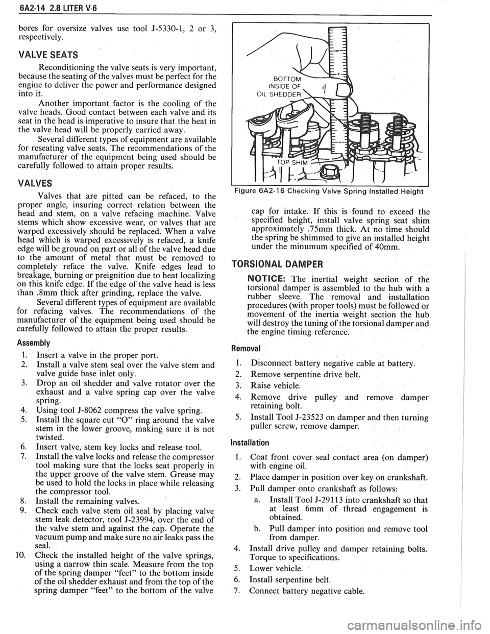
Check the installed height of the valve springs,
using
a narrow thin scale. Measure from the top
of the spring damper "feet" to the bottom inside
of the oil shedder exhaust and from the top of the
spring damper "feet" to the bottom of the valve
Figure 6A2-16 Checking Valve Spring Installed Height
cap for intake. If this is found to exceed the
specified height, install valve spring seat shim
approximately
.75mm thick. At no time should
the spring be shimmed to give an installed height
under the
minumum specified of 40mm.
TORSIONAL DAMPER
NOTICE: The inertial weight section of the
torsional damper is assembled to the hub with a
rubber sleeve. The removal and installation
procedures (with proper tools) must be followed or
movement of the inertia weight section the hub
will destroy the tuning of the torsional damper and
the engine timing reference.
Removal
1.
Disconnect battery negative cable at battery.
2. Remove serpentine drive belt.
3. Raise vehicle.
4. Remove drive pulley and remove damper
retaining bolt.
5. Install Tool J-23523 on damper and then turning
puller screw, remove damper.
Installation ,
1.
Coat front cover seal contact area (on damper)
with engine oil.
2. Place damper in position over key on crankshaft.
3. Pull damper onto crankshaft as follows:
a. Install
Tool J-29 1 13 into crankshaft so that
at least 6mm of thread engagement is
obtained.
b. Pull damper into position and remove tool
from damper.
4. Install drive pulley and damper retaining bolts.
Torque to specifications.
5. Lower vehicle.
6. Install serpentine belt.
7. Connect battery negative cable.
Page 453 of 1825
6D2-2 CRANKING SYSTEM
1-SWIFT LEVER m
SPRING 17-FLYWHEEL I
I G20198-6D
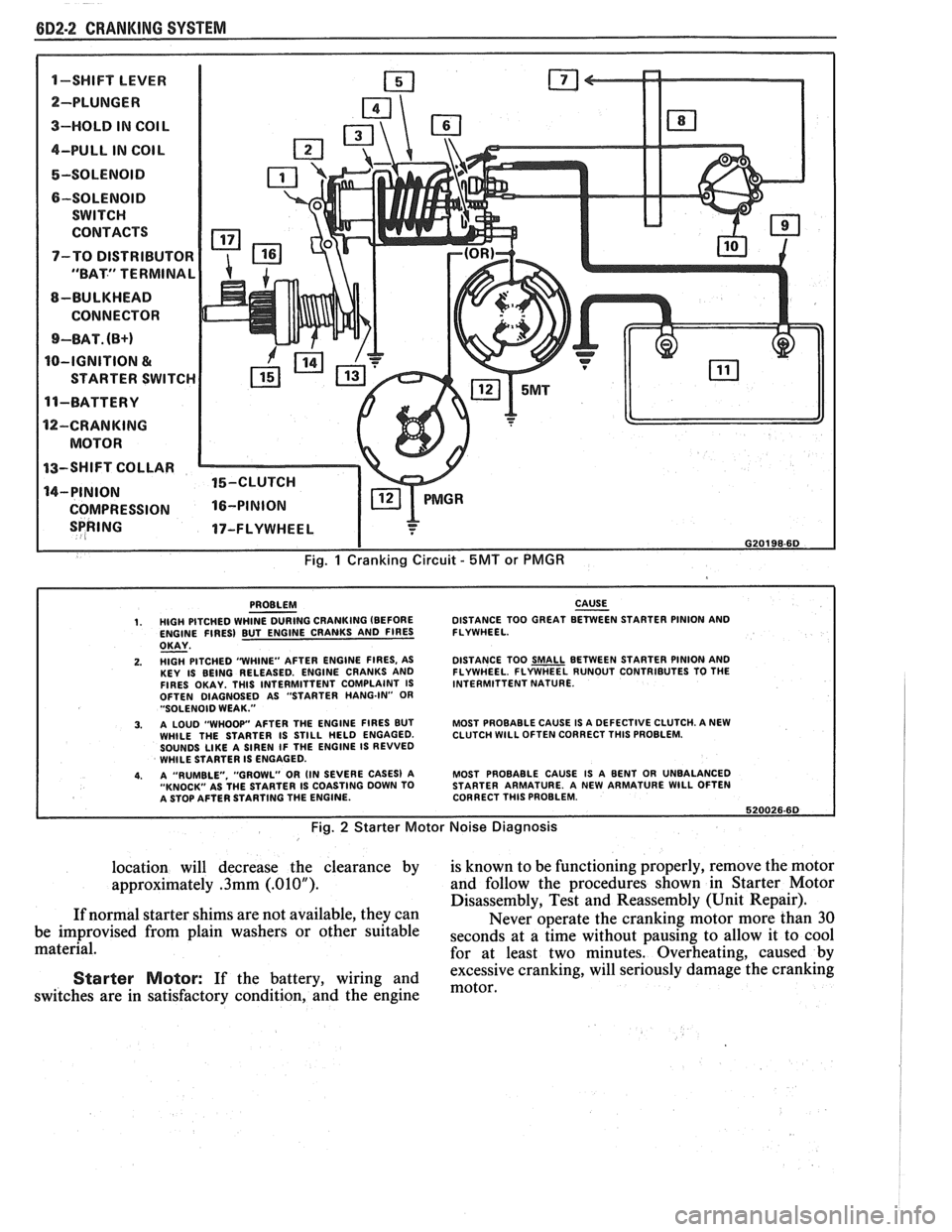
Fig. 1 Cranking Circuit - 5MT or PMGR
PROBLEM CAUSE - 1. HIGH PITCHED WHINE DURING CRANKING (BEFORE DISTANCE
TOO GREAT BETWEEN STARTER PINION AND
ENGINE FIRES) BUT ENGINE CRANKS AND FIRES FLYWHEEL.
OKAY - 2. HlGH PITCHED "WHINE"
AFTER ENGINE FIRES, AS
KEY IS BEING RELEASED. ENGINE CRANKS AND
FIRES OKAY. THlS INTERMITTENT COMPLAINT IS
OFTEN DIAGNOSED AS "STARTER HANG-IN"
OR "SOLENOID WEAK."
3. A LOUD "WHOOP" AFTER THE ENGINE FIRES BUT
WHILE THE STARTER IS STILL HELD ENGAGED.
SOUNDS
LIKE A SIREN IF THE ENGINE IS REVVED
WHILE STARTER IS ENGAGED.
4. A "RUMBLE. "GROWL" OR (IN SEVERE CASES) A
"KNOCK" AS THE STARTER IS COASTING DOWN TO
A STOP AFTER STARTING THE ENGINE. DISTANCE
TOO
SMALL BETWEEN STARTER PINION AND
FLYWHEEL. FLYWHEEL RUNOUT CONTRIBUTES TO THE
INTERMITTENT NATURE.
MOST PROBABLE CAUSE IS A DEFECTIVE CLUTCH. A NEW
CLUTCH
WlLL OFTEN CORRECT THlS PROBLEM.
MOST PROBABLE CAUSE IS A BENT OR UNBALANCED
STARTER ARMATURE. A NEW ARMATURE
WlLL OFTEN
CORRECT THlS PROBLEM.
620026.60
Fig. 2 Starter Motor Noise Diagnosis
location will decrease the clearance by is known to be functioning properly, remove the motor
approximately
.3mm (.01OU). and follow the procedures shown in Starter Motor
Disassembly, Test and Reassembly (Unit Repair).
If normal starter shims are not available, they can
Never operate the cranking motor more than 30
be improvised from plain washers or other suitable
seconds at a time without pausing to allow it to cool material.
for at least two minutes. Overheating, caused by
excessive cranking, will seriously
damage the cranking Starter Motor: If the battery, wiring and motor, switches are in satisfactory condition, and the engine
Page 483 of 1825
8B-2 ENGINE ELECTRICAL
NO CRANKING, NO SOUND FROM SOLENOID
I TURN HEADLIGHTS AND DME LITE ON
TURN KEY TO START I
TEST BETTERY.
IF OK. REPAIR
.5 VOLT OR MORE a
OSITION, (POS. LEAD 0
GROUND CABLE CONN. ANDlOR REPLACE
CABLE.
CLEAN AND TIGHTEN
POS. BATTERY CABLE
TERMINALS
ANDlOR REPLACE CABLE. CONNECTOR.
FUSIBLE
CHECK CONNECTIONS
AND VOLTAGE AT
SOLENOID
"S' TERM.
LESS THAN
7 VOLTS b
FAULTY PURPLE WITH KEY IN START,
WIRE TO STARTER CHECK
VOLTAGE AT
G20201-6D
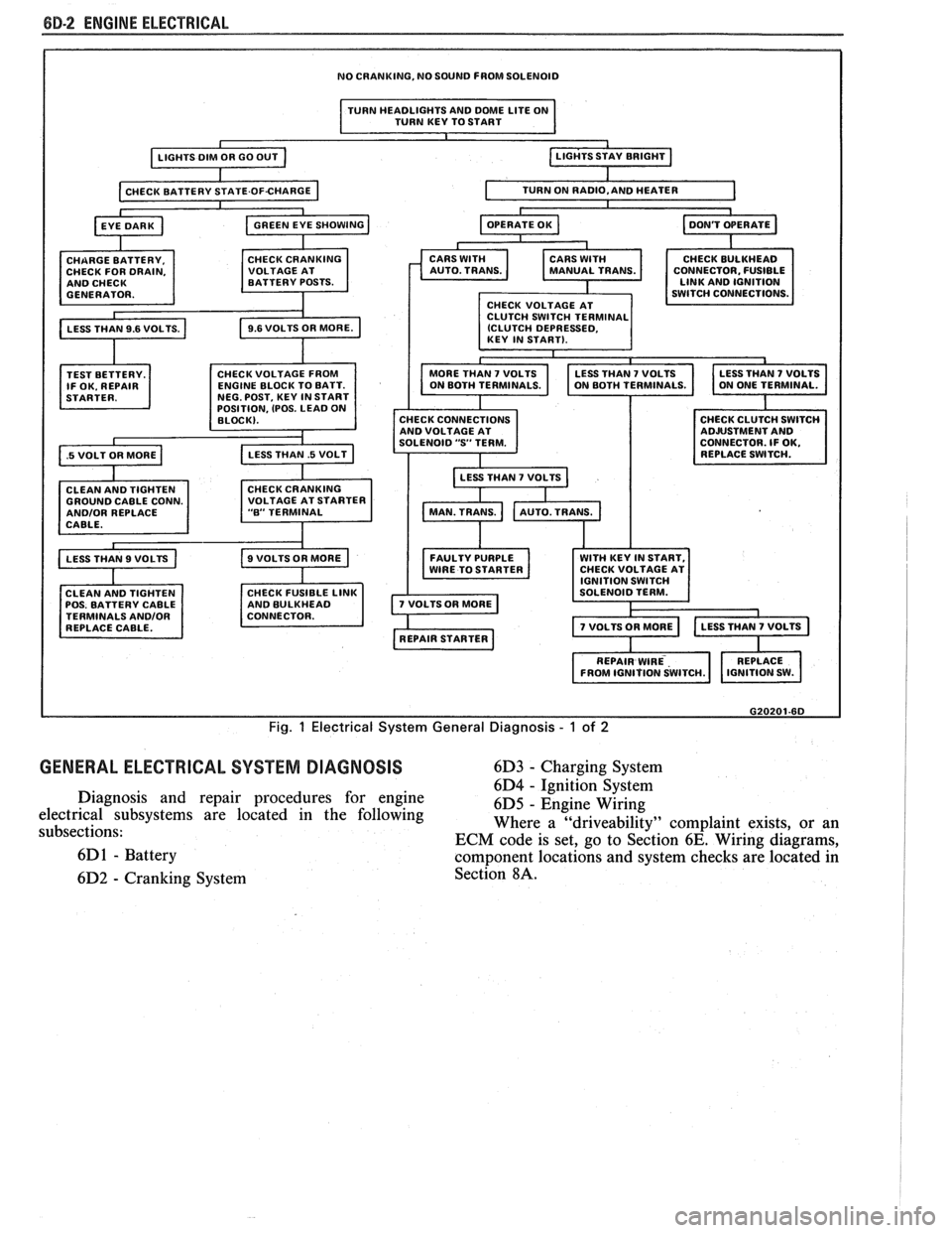
Fig. 1 Electrical System General Diagnosis - 1 of 2
GENERAL ELECTRICAL SYSTEM DIAGNOSIS 6D3 - Charging System
6D4
- ~~nitcon-§~stem Diagnosis and repair procedures for engine
6D5 - Engine Wiring
electrical subsystems are located in the following
subsections: Where a
"driveability" complaint
exists, or an
ECM code is set, go to Section
6E. Wiring diagrams,
6D
1 - Battery component locations and system checks are located in
6D2
- Cranking System Section 8A.
Page 484 of 1825
ENGINE ELECTRICAL 6D-3
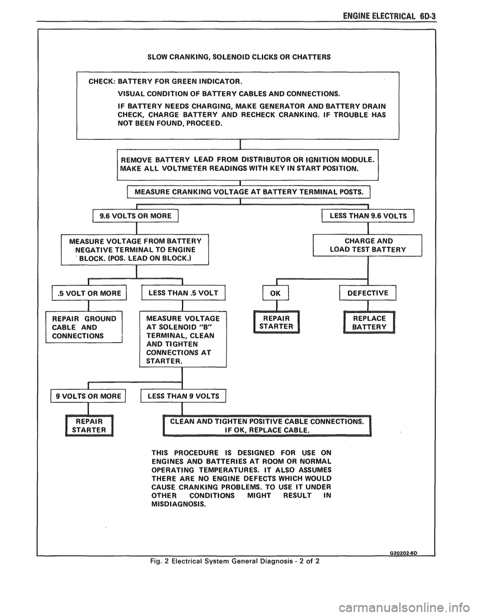
SLOW CRANKING, SOLENOID CLICKS OR CHATTERS
VISUAL CONDITION OF BATTERY CABLES AND CONNECTIONS.
IF BATTERY NEEDS CHARGING, MAKE GENERATOR AND BATTERY DRAIN
CHECK, CHARGE BATTERY AND RECHECK CRANKING. IF TROUBLE HAS
NOT BEEN FOUND, PROCEED.
AKE ALL VOLTMETER READINGS
WITH KEY IN START POSITION.
CABLE AND AT SOLENOID
"8"
TERMINAL, CLEAN
AND TIGHTEN
CONNECTIONS AT
THIS PROCEDURE IS DESIGNED FOR USE ON
ENGINES AND BATTERIES AT ROOM OR NORMAL
OPERATING TEMPERATURES. IT ALSO ASSUMES
THERE ARE NO ENGINE DEFECTS WHICH WOULD
CAUSE CRANKING PROBLEMS. TO USE IT UNDER
OTHER CONDITIONS MIGHT RESULT IN
MISDIAGNOSIS.
Fig. 2 Electrical System General Diagnosis - 2 of 2
Page 505 of 1825
6E2-A-114 5.OL (VIN E) DRIVEABILITY AND EMISSIONS
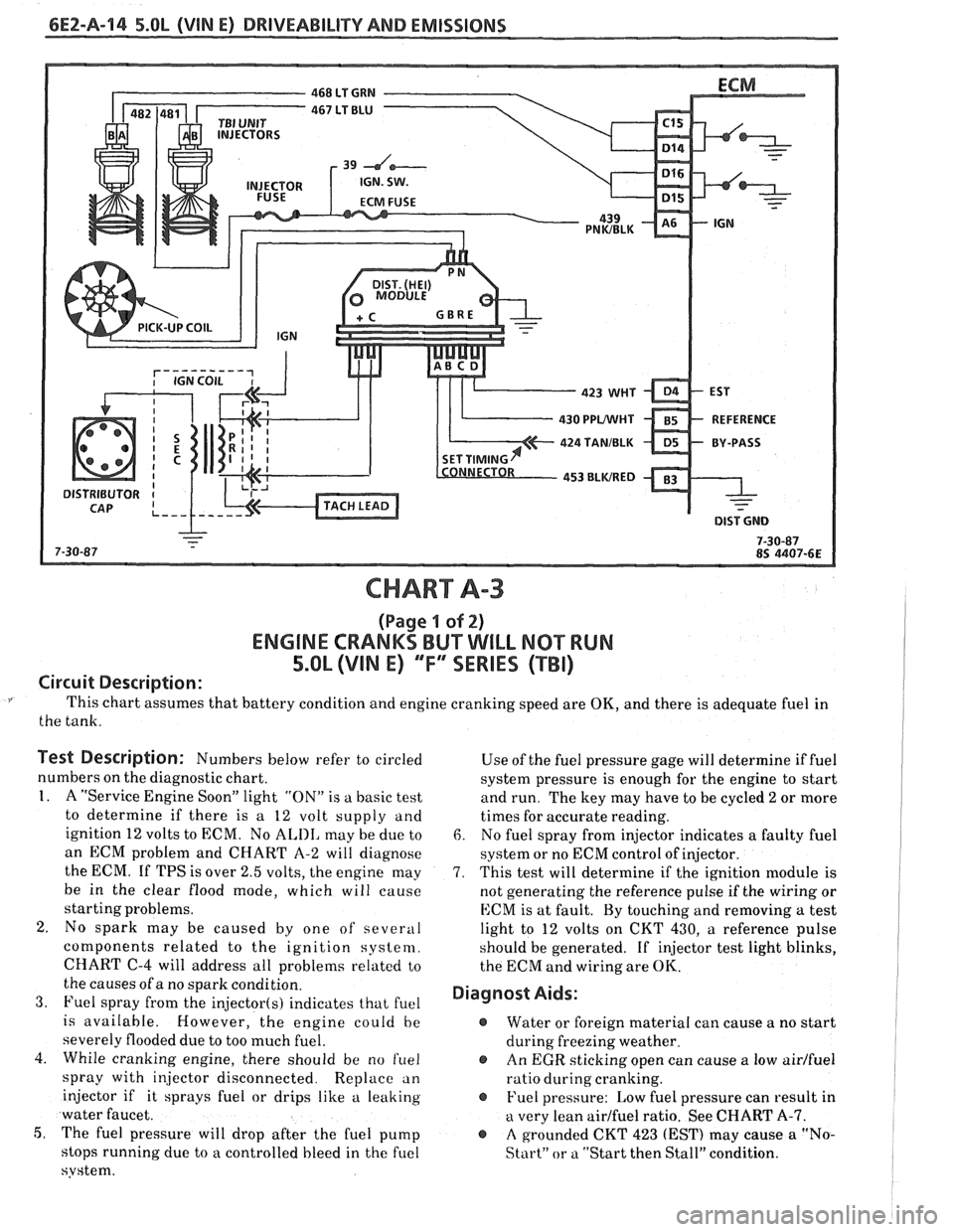
CHART A-3
(Page I of 2)
ENGINE CRANKS BUT WILL NQ"TRUN
5.OL (VIM E) "F"" SERlES (TBI)
Circuit Description:
This chart assumes that battery condition and engine cranking speed are OK, and there is adequate fuel in
the tank.
Test Description: Numbers below refer to circled
numbers on the diagnostic chart.
1. A "Service Engine Soon" light "ON" is a basic test
to determine if there is a 12 volt supply and
ignition 12 volts to ECM. No
ALIII, may be due to
an ECM problem and CHART A-2 will diagnose
the ECM. If TPS is over 2.5 volts, the engine may
be in the clear flood mode, which will cause
starting problems.
2. No spark may be caused by one of several
components related to the ignition system.
CHART
C-4 will address all problems related to
the causes of a no spark condition.
3. Fuel spray from the injector(s) indicates that fuel
is available. However, the engine could be
severely flooded due to too much fuel.
4. While cranking engine, there should be no
f~lel
spray with injector disconnected. Replace an
injector if it sprays fuel or drips like a leaking
water faucet.
5, The fuel pressure will drop after the fuel pump
stops running due to
a controlled bleed in the fuel
system. Use
of the fuel pressure gage will determine
if fuel
system pressure is enough for the engine to start
and run. The key may have to be cycled
2 or more
times for accurate reading.
6. No fuel spray from injector indicates a faulty fuel
system or no ECM control of injector.
7. This test will determine if the ignition module is
not generating the reference pulse if the wiring or
ECM is at fault. By touching and removing
a test
light to 12 volts on CKT 430,
a reference pulse
should be generated. If
injector test light blinks,
the ECM and wiring are
OK.
Diagnost Aids:
@ Water or foreign material can cause a no start
during freezing weather.
@ An EGR sticking open can cause a low airlfuel
ratio during cranking.
@ Fuel pressure: Low fuel pressure can result in
a very lean airlfuel ratio. See CHART A-7.
@ A grounded CKT 423 (EST) may cause a "No-
Start" or a "Start then Stall" condition.
Page 509 of 1825
6EZ-Pa-18 5.OL (VIN E) DRIVEABILITY AND EMISSIONS
FUEL PUMP
RELAY CONN.
465 DK GRNMIHT
450 BLWHT
FUEL PUMP
BATTERY JUNCTION TEST TERM. BULKHEAD BODY CONNECTOR
BLOCK
(1 2 VOLT) CONNECTOR
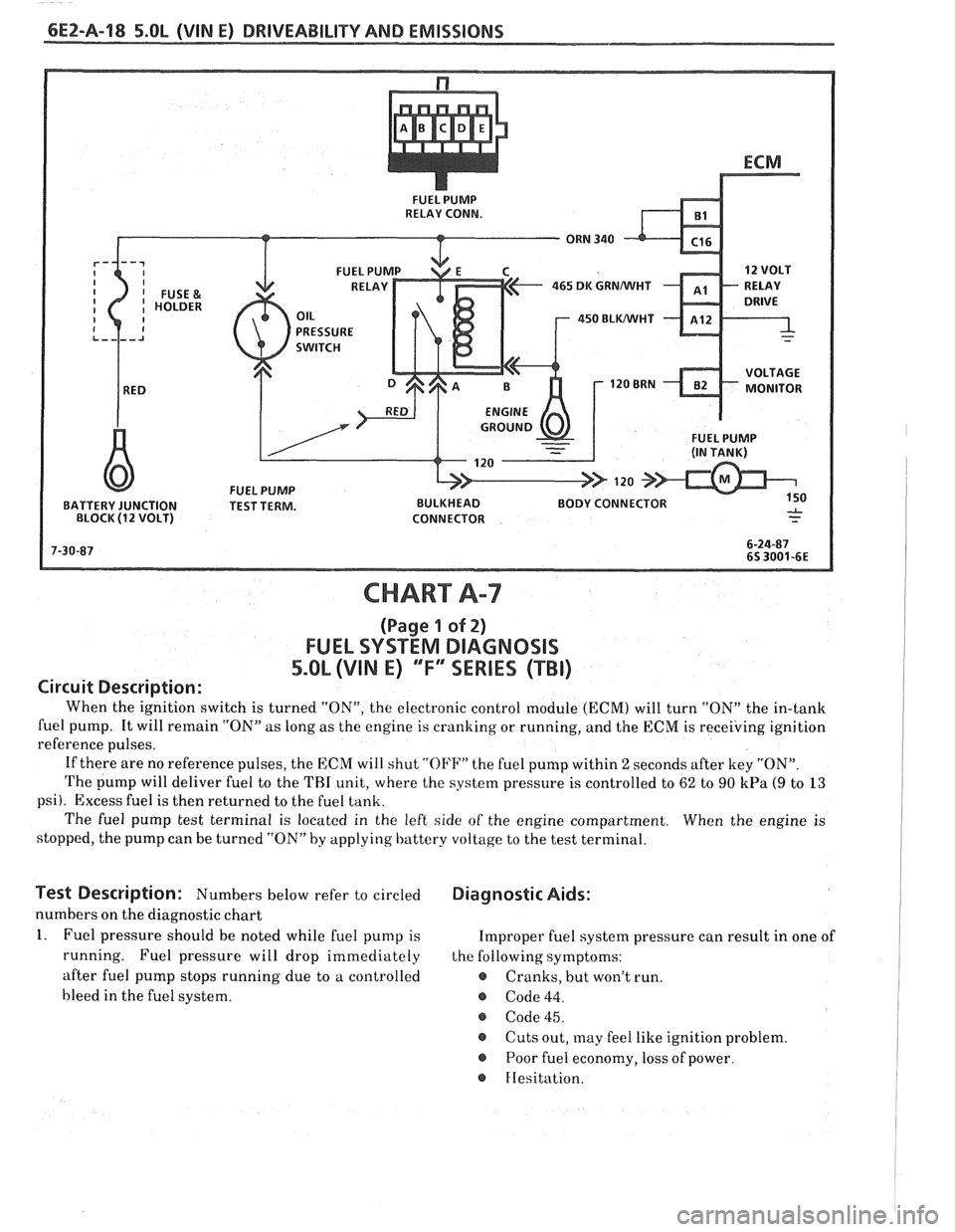
CHART A-7
(Page 1 of 2)
FUEL SYSTEM DlAGNOSlS
5.0L (VIN E) "F"" SERIES (TBI)
Circuit Description:
When the ignition switch is turned "ON", the electronic control module (ECM) will turn "ON" the in-tank
fuel pump. It will remain "ON"
as long as the engine is cranking or running, and the ECM is receiving ignition
reference pulses.
If there are no reference pulses, the ECM will shut
"OI'F" the fuel pump within 2 seconds after key "ON".
The pump will deliver fuel to the THI unit, where the system pressure is controlled to 62 to 90 kPa (9 to 13
psi). Excess fuel is then returned to the fuel tank.
The fuel pump test terminal is located in the left side of the engine compartment. When the engine is
stopped, the pump can be turned "ON" by applying battery voltage to the test terminal.
lest Description: Numbers below refer to circled Diagnostic Aids:
numbers on the diagnostic chart
1. Fuel pressure should be noted while fuel pump is Improper fuel system pressure can result in one of
running. Fuel pressure will drop immediately the following symptoms:
after fuel pump stops running due to a controlled
e Cranks, but won't run.
bleed in the fuel system.
@ Code 44.
@ Code 45.
@ Cuts out, may feel like ignition problem.
@ Poor fuel economy, loss of power.
FIesitation.