light PONTIAC FIERO 1988 Service Owner's Guide
[x] Cancel search | Manufacturer: PONTIAC, Model Year: 1988, Model line: FIERO, Model: PONTIAC FIERO 1988Pages: 1825, PDF Size: 99.44 MB
Page 152 of 1825
STEERING WHEELS AND COLUMNS 385.1
SECTION 3B5
STEER NG WHEELS AND COLUMNS
NOTICE: All steering wheel and column fasteners are important attaching parts in that they could affect
the performance of vital parts and systems, and/or could result in major repair expense. They
must be replaced
with one of the same part number or with an equivalent part if
replacement becomes necessary. Do not use a
replacement part of lesser quality or substitute design. 'Torque values must be used as specified during reassembly
to assure proper retention of all parts. There is to be no welding as
it may result in extensive damage and weakening
of the metal.
For prevailing torque
nut(s) and bolts(s), refer to the "Reuse of Prevailing Torque Nut(<) and Bolt(s) " chart
in Section OA.
CONTENTS
..................... ................................................................... GENERAL DESCRIPTION .. 3B5-1 ............................................. ........................ MAINTENANCE AND ADJUSTMENTS .. 3B5-1 ON-CAR SERVICE ........................................................................................................ 3B5-2
Steering Column ............................................................................................................ 3B5-2 ......................................................................................................... Intermediateshaft 3B5-3
Park Lock Cable .................................................................... 3B54 ......................................................................................... Checking For Accident Damage 3B5-5 ............................................................................ Unit Repair Intermediate Shaft Assembly 3B5-6
..................................................................................... Standard Column @lanual Trans) 3B5-7 ......................................................... ....................... Standard Column (Auto Trans) .. 3B5-13 Tilt Column (Manual Trans) ............................................................................................. 3B5-19
Tilt Column (Auto Trans). ................................................................................................ 3B5-27
................ .................... TORQUE SPECIFICATIONS .. .. 3B5-35
SPECIAL TOOLS .......................................................................................................... 3B5-35
GENERAL DESCRIPTION
STEERING COLUMN
The function locking energy absorbing steering
column includes three important features in addition
to the steering function:
1. 'The column is energy absorbing, designed to
compress in a front-end collision to minimize the
possibility of an injury to the driver of the car.
2. The ignition switch and lock are mounted
conveniently on this column.
3. With the column mounted lock, the ignition and
steering operations can be locked to inhibit theft
of the car.
The turn signal lever provides for control of
headlight beams, windshield washer and wipers.
The column may be easily
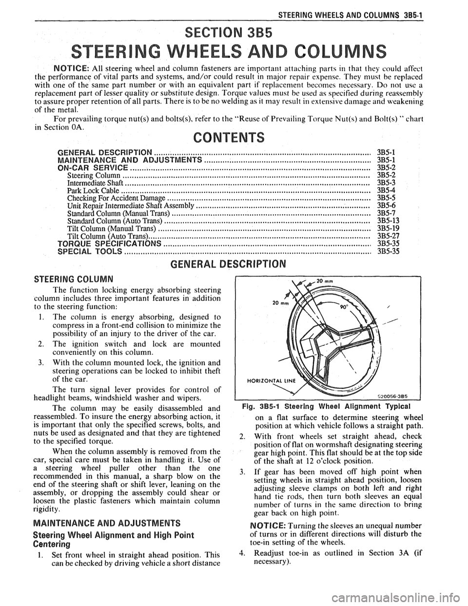
disassembled and Fig. 385-1 Steering Wheel Alignment ~ypical
reassembled. To insure the energy absorbing action, it
on a flat surface to determine steering wheel
is important that only the specified screws, bolts, and
position at which vehicle follows a straight path.
nuts be used as designated and that they are tightened
2. With front wheels set straight ahead, check to the specified torque.
position of flat on wormshaft designating steering
When the column assembly is removed from the
gear high point. This flat should be at the top side
car, special care must be taken in handling it. Use of
of the shaft at 12 o'clock position.
a steering puller other than the One 3, if gear has been moved off high when recommended in this manual, a sharp blow on the
setting wheels in straight ahead position, loosen
end of the steering shaft or shift lever, leaning on the
assembly, or dropping the assembly could shear or adjusting
sleeve clamps on both left and right
hand tie rods, then turn both sleeves an equal
loosen the plastic fasteners which maintain column
rigidity. number
of turns in the same direction
to bring
gear back
on high point.
MAINTENANCE AND ADJUSTMENTS NOTICE: Turning the sleeves an unequal number
Steering Wheel Alignment and High Point of turns or in different directions will disturb the
Centering toe-in setting of the wheels.
1. Set front wheel in straight ahead position, This 3. Readjust toe-in as outlined in Section 3A (if
can be checked by driving vehicle
a short distance necessary).
Page 194 of 1825
POWER Sf EERING 387-1
SECTION 3B7
POWER STEER NG GEAR AND PUMP
The following notice applies to one or more steps in the assembly procedure of components in this portion
of the manual as indicated at appropriate locations. "See Notice on Page
1 of this Section".
NOTICE: Steering column fasteners are important attaching parts in that they may affect the performance
of vital components and systems, and/or could result in major repair expense. They must be replaced with one
of the same part number or with an equivalent part if replacement becomes necessary. Do not use a replacement
part of lesser quality or substitute design. Torque values must be used as specified during reassembly to assure
proper retention of these parts. For prevailing torque
nut(s) and bolt(s), refer to the "Reuse of Prevailing Torque
Nut(s) and Bolt(s)" chart in Section 10.
CONTENTS
MAINTENANCE AND ADJUSTMENTS
Bleeding Hydraulic System
................................................................................................. 3B7- 1
Fluid Level ......................................................................................................................... 3B7- 1
Power Steering Gear Adj. ..................................................................................................... 3B7- 1
Drive Belt Tension .............................................................................................................. 3B7-2
Hydraulic System Checks .................................................................................................. 3B7-2
Hydraulic System Test ......................................................................................................... 3B7-2
ON-VEHICLE SERVICE
Steering Gear Removal
...................................................................................................... 3B7-3
Pitman Shaft Seal .................................................................................................................. 3B7-3
Pump Removal ..... , ................................................................................................................ 3B7-4
................................................................................................................... Hoses and Pipes 3B7-4
Pump Pulley ....................................................................................................................... 3B7-4
.................................................................................. Pump Brackets/Hoses/Cooling Pipes 3B7-5
........................................................................................ Pump Overhaul .................... ..... 3B7- 12
Gear Overhaul .................................................................................................................... 3B7- 13
SPECIAL TOOLS ............................................................................................................ 3B7-17 ......................... .......................................................... GENERAL SPECIFICATIONS .. 3B7- 18
MAlNKNANGE AND ADJUSTMENTS
BLEEDING HYDRAULIC SYSTEM
Fill fluid reservoir to proper level and let remain
undisturbed for at least two minutes.
Start engine and run momentarily.
Shut engine off to add fluid.
Repeat above procedure until fluid level remains
constant after running engine.
Raise front end of vehicle so that wheels are off
the ground.
Start engine and increase engine speed to
approximately
1500 rpm.
Turn the wheels (off ground) right and left,
lightly contacting the wheel stops.
Lower the car and turn wheels right and left on
the ground.
Shut engine off, check fluid level and refill as
required.
If fluid is extremely foamy, allow vehicle to stand
a few minutes with engine off while you run
through the following:
a. Check belt
tightness and check for a bent or
loose pulley. (Pulley should not wobble with
engine running.) b.
Check
to make sure hoses are not touching
any other parts of the car, particularly sheet
metal and exhaust manifold.
c. Check fluid
level, filling to proper level if
necessary. Air in the fluid is the most
frequent cause of objectionable pump noise.
d. When air is present, bleed system as
described in operations 1 through 10. If the
pump will not bleed after a few trials,
proceed as outlined under Hydraulic
System Checks. FLUID LEVEL
1. Check fluid level in the reservoir by checking the
dip stick when fluid is at operating temperature.
2. Fill, if necessary, to proper level with GM Power
Steering Fluid, or equivalent.
POWER STEERING GEAR ADJUSTMENTS
Adjustment of the power steering gear in the
vehicle is discouraged because of the difficulty involved
in adjusting the worm thrust bearing preload and the
confusing effects of the hydraulic fluid in the gear. The
steering gear adjustment is made only as a correction
and not as a required periodic adjustment.
Page 203 of 1825

3B7-10 POWER STEERING
I. REMOVE AND INSTALL DRlVE SHAFT SEAL W l THOUT DISASSEMBL ING THE PUMP.
REMOVE It6TALL
I PROTECT DRlVE SHAFT I COAT DRIVE SHAFT SEAL WITH SHIM STOCK WITH HYDRAULIC PVMP 2 USE Ch 5EL TO CUT FLUID. REFER TO INSET FOR
SEAL AND REMOVE DRIVE SHAFT SEAL INSTALLATION
DRAUCIC WMP ASSEMBLY
TOOL J-7728
1
i
j
I
2. REMOVE AND INSTALL PUMP RESERVOIR ASSEMBLY I REMOVE INSTALL I I. DRAIN OIL FROM RESERVOIR I. USE ALL NEW SEALS AND LUBRICATE
ASSEMBLY BEFORE REMOVAL. WlTH
POWER STEERING FLUID BEFORE 2. REMOVE PARTS AS SHOWN. INSTALLAT
ION. 2. INSTALL PARTS AS SHOWN.
TORQUE TO SJ N m
FITTING ASSEMBLY
TORQUE TO 50 N m
UMP REYRVOIR ASSEMBLY *
O-RING SEALS * . NOT USED ON
HOUSING ASSEMBLY 125-N SERIES
1 1 I
REFER TO INSET FOR I. LLleRlCATE EN) PLATE AND I RETAINING RING. INSTALL
PARTS AS WOWN. REFER TO
INSET FOR POSITIONING
OF I
I RETAINING RING 1
- - - - - - - LOCATE RlNG GAP I REMOVE RETAINING RING AT POSITION WOWN I
POSITIONING OF RETAINING
ATE RETAINING RlNG
VALVE
ASSEWY
OW CONTROL SPRING
LWTI(X : BEFORE PROCEEDING. EXAMIN THIS
PART Of TM DRIVE WAFT. IF IT IS C CROCUS CLOTH BEFORE REMOVING. THIS WILL PREVENT DAMAGE TO TM WAFT WING WHICH MIGHT REWIRE RERACEMNT OF 1% ENTIRE HOUSING.
-- J RING.
4. REMOVE AND INSTALL ROTATING GROUP.
REMOVE INSTALL
1. USING A RUBBER MALLET. I. INSTALL PARTS AS SHOWN ON
TAP LIGHTLY ON DRIVE
DRIVE WAFT. INSTALL NEW
WAFT UNTIL
PRESSVRE RETAINING RING ON DRIVE
PLATE IS FREE. SHAFT AND INSTALL IN PW 2. REMOVE RETAINING RING HOUSING.
FROM DRlVE WAFT AM 2, REFER TO INSET FOR POSITIONING
DISCARD. REMOVE PARTS OF PUMP RING IN HOUSING.
AS SHOWN.
7 VANES r------I T PRESSURE PLATE '1 NOTICE: INSTALL WITH
ROUNDED EDGE OF VANES OVTWARD.
WAFT. ROTOR AN) TWST PLATE ASSEMBLY
PUIAP RING.
C
\- HOUSING ASSEMLY
TpW ROTOR
WAFT RETAINING
I RETAINING RlNG REMOVAL I
5. REMOVE AND INSTALL DRIVE SHAFT AND
O-RING SEALS.
I RLAOM INSTML
I. REMOVE PARTS 1. REFER TO TM INSET FOR DRlVE
AS WOWN WAFT SEAL INSTALLATION
USE ALL NW SEALS AND 1 LVBRlCATE SEALS WlTH POWER J-7728 STEERING FLUID BEFORE
INSTALLATION
! 2. INSTALL PARTS AS WOWN .
I
INSTALL DRIVE SHAFT
HOUSING ASSEMBLY
I LDRIVE WAFT SEAL
BENCH REPAIR
Figure 3B7-11 Power Steering Pump Overhaul
Page 235 of 1825
3E.4 TIRES AND WHEELS
TIRE CHAIN USAGE
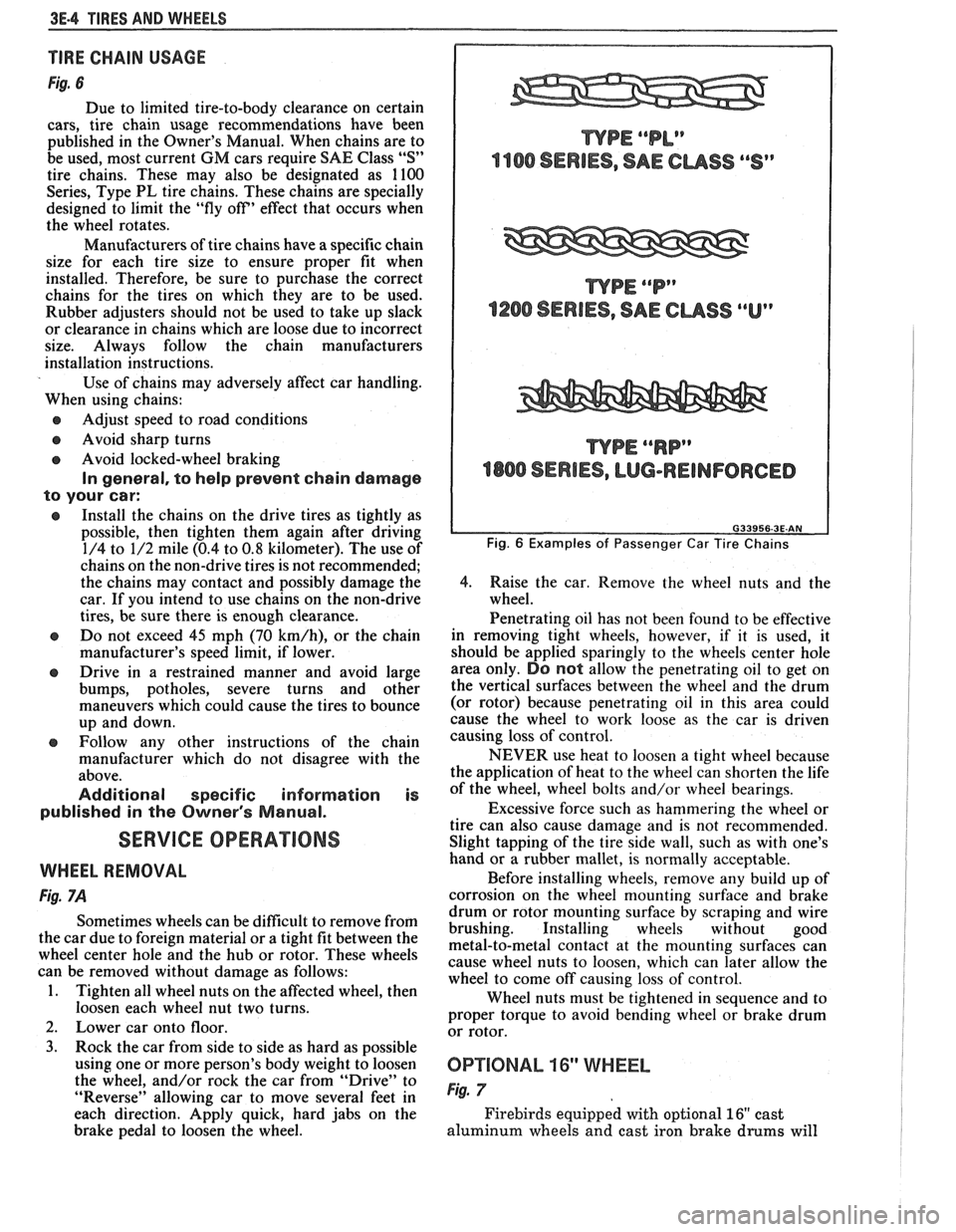
Fig. 6
Due to limited tire-to-body clearance on certain
cars, tire chain usage recommendations have been
published in the Owner's Manual. When chains are to
be used, most current
GM cars require SAE Class "S"
tire chains. These may also be designated as 1100
Series, Type PL tire chains. These chains are specially
designed to limit the "fly off' effect that occurs when
the wheel rotates.
Manufacturers of tire chains have a specific chain
size for each tire size to ensure proper fit when
installed. Therefore, be sure to purchase the correct
chains for the tires on which they are to be used.
Rubber adjusters should not be used to take up slack
or clearance in chains which are loose due to incorrect
size. Always follow the chain manufacturers
installation instructions.
Use of chains may adversely affect car handling.
When using chains:
@ Adjust speed to road conditions
@ Avoid sharp turns
@ Avoid locked-wheel braking
In general, to help prevent chain damage
to your car:
@ Install the chains on the drive tires as tightly as
possible, then tighten them again after driving
1/4 to 1/2 mile (0.4 to
0.8 kilometer). The use of
chains on the non-drive tires is not recommended;
the chains may contact and possibly damage the
car. If you intend to use chains on the non-drive
tires, be sure there is enough clearance.
e Do not exceed 45 mph (70 km/h), or the chain
manufacturer's speed limit, if lower.
@ Drive in a restrained manner and avoid large
bumps, potholes, severe turns and other
maneuvers which could cause the tires to bounce
up and down.
e Follow any other instructions of the chain
manufacturer which do not disagree with the
above.
Additional specific information is
published in the Owner's Manual.
SERVICE OPERATIONS
WHEEL REMOVAL
Fig. 7A
Sometimes wheels can be difficult to remove from
the car due to foreign material or a tight fit between the
wheel center hole and the hub or rotor. These wheels
can be removed without damage as follows:
1. Tighten all wheel nuts on the affected wheel, then
loosen each wheel nut two turns.
2. Lower car onto floor.
3. Rock the car from side to side as hard as possible
using one or more person's body weight to loosen
the wheel, and/or rock the car from
"Drive" to
"Reverse" allowing car to move several feet in
each direction. Apply quick, hard jabs on the
brake pedal to loosen the wheel.
WPE ""P"
1200 SERIES, SAE CUSS ""Up
WPE ""RP"
4800 SERIES, LUG-REINFORCED
Fig. 6 Examples of Passenger Car Tire Chains
4.
Raise the car. Remove the wheel nuts and the
wheel.
Penetrating oil has not been found to be effective
in removing tight wheels, however,
if it is used, it
should be applied sparingly to the wheels center hole
area only.
DO not allow the penetrating oil to get on
the vertical surfaces between the wheel and the drum
(or rotor) because penetrating oil in this area could
cause the wheel to work loose as the car is driven
causing loss of control.
NEVER use heat to loosen a tight wheel because
the application of heat to the wheel can shorten the life
of the wheel, wheel bolts and/or wheel bearings.
Excessive force such as hammering the wheel or
tire can also cause damage and is not recommended.
Slight tapping of the tire side wall, such as with one's
hand or a rubber mallet, is normally acceptable.
Before installing wheels, remove any build up of
corrosion on the wheel mounting surface and brake
drum or rotor mounting surface by scraping and wire
brushing. Installing wheels without good
metal-to-metal contact at the mounting surfaces can
cause wheel nuts to loosen, which can later allow the
wheel to come off causing loss of control.
Wheel nuts must be tightened in sequence and to
proper torque to avoid bending wheel or brake drum
or rotor.
0P"FIONAL 16" WHEEL
Fig. 7
Firebirds equipped with optional 16" cast
aluminum wheels and cast iron brake
drums will
Page 236 of 1825
TIRES AND WI4EELS 3E-5
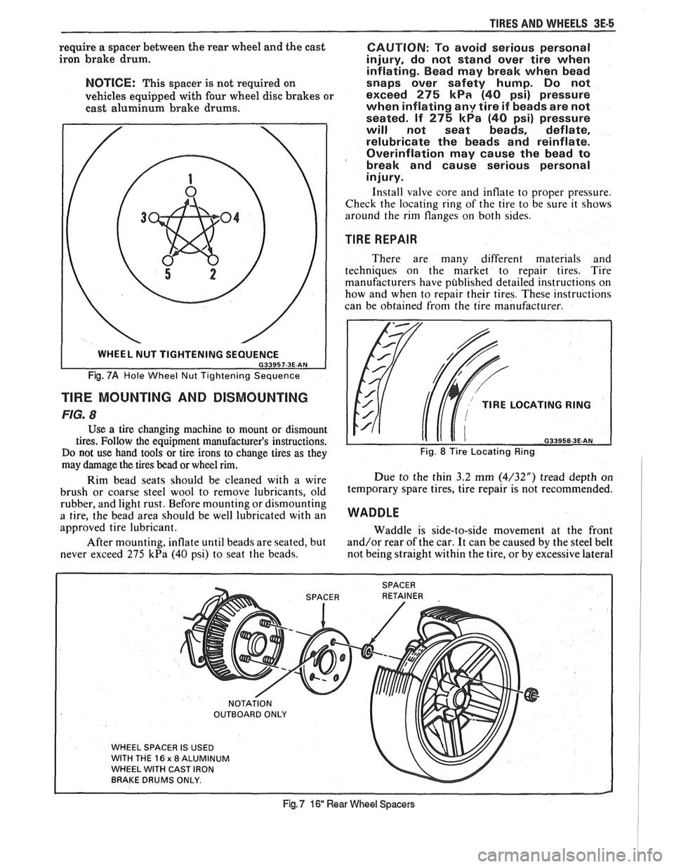
require a spacer between the rear wheel and the cast
iron brake drum.
NOTICE: This spacer is not required on
vehicles equipped with four wheel disc brakes or
cast aluminum brake drums.
Fig. 7A Hole Wheel Nut Tightening Sequence
TlRE MOUNTING AND DISMOUNTING
FIG. 8
Use a tire changing machine to mount or dismount
tires. Follow the equipment manufacturer's instructions.
Do not use hand tools or tire irons to change tires as they
may damage the tires bead or wheel rim.
Rim bead seats should be cleaned with a wire
brush or coarse steel wool to remove lubricants, old
rubber, and light rust. Before mounting or dismounting
a tire, the bead area should be well lubricated with an
approved tire lubricant.
After mounting, inflate until beads are seated, but
never exceed 275
kPa (40 psi) to seat the beads.
CAUTION: To avoid serious personal
injury, do not stand over tire when
inflating. Bead may break when bead
snaps over safety hump. Do not
exceed
275 kPa (40 psi) pressure
when inflating
any tire if beads are not
seated. If
275 kPa (40 psi) pressure
will not seat beads, deflate,
relubricate the beads and reinflate.
Overinflation may cause the bead to
break and cause serious personal
injury.
Install valve core and inflate to proper pressure.
Check the locating ring of the tire to be sure it shows
around the rim flanges on both sides.
TIRE REPAIR
There are many different materials and
techniques on the market to repair tires. Tire
manufacturers have published detailed instructions on
how and when to repair their tires. These instructions
can be obtained from the tire manufacturer.
TlRE LOCATING RING
naaaca a= AM
Fig. 8 Tire Locating Ring
Due to the thin 3.2 mm (4/32") tread depth on
temporary spare tires, tire repair is not recommended.
WADDLE
Waddle is side-to-side movement at the front
and/or rear of the car. It can be caused by the steel belt
not being straight within the tire, or by excessive lateral
WHEEL SPACER IS USED
WITH THE
16 x 8 ALUMINUM
WHEEL WITH CAST IRON
BRAKE DRUMS ONLY.
Fig, 7 16 Rear Wheel Spacers
Page 241 of 1825
3E-10 TIRES AND WHEELS
Clear Coat Damage on Unpainted Wheels
I.
Apply chemical stripper. Use small 1/4" detail
brush dipped in stripper to apply material around
perimeter and spoke-like areas.
2. Remove stripper following manufacturers
recommendations.
3. Sand wheel with 240 grit while rotating wheel on
a slow spinning brake lathe or by mounting on car
and spinning by hand. This will restore the
machined appearance and promote adhesion.
CAUTION: Do not use engine power to
rotate wheel while sanding to avoid
serious personal injury.
4. Continue with "Recoating Procedure."
Recoating Procedure
1. Clean surface of contaminants.
2. Soak wheel with Amchem #33 or equivalent
from
1 to 3 minutes, then rinse with water and
blow dry.
3. Soak wheel with Amchem
#I001 or equivalent
for
1 to 3 minutes, then rinse with water and blow
dry. 4.
Finish with Ditzler Delclear Acrylic Urethane
and Ditzler Ultra-Urethane Additive or
equivalent using three coats.
1st Coat
- Light mist coat, let flash
2nd Coat
- Light, let flash
3rd Coat
- Heavy double wet coat
CAUTION: To avoid serious personal
injury when applying any two part
component paint system, follow the
specific precautions provided by the
paint manufacturer. Failure to follow
these precautions may cause lung
irritation and allergic respiratory
reaction.
5. Let dry for 24 hours - (or flash for 30 minutes,
force dry at
140" for 30 minutes, and allow to cool
for 30 minutes before mounting.
WHEEL NUT TORQUE
F Carline - M 12X 1.5 .............. 1 10 N . m (80 Ibs. ft.)
Page 244 of 1825
PROPELLER SHAFT $A-3
B. If companion flange run-out is over 0.15mm (.006
in.) but less than 0.28mm (.011 in.) and balance
weight is at or near low point of companion flange
run-out, no further action is required.
If balance weight is not at or near low point of
companion flange run-out, remove weight.
6. If companion flange run-out is over 0.28mm (.011
in.), but no greater than 0.38mm (.015 in.) and
balance weight is at or near low point of
companion flange run-out, no further action is
required.
If balance weight is not at or near low point of
companion flange
runout, remove weight and
reindex companion flange until run-out is 0.25
mm
(.010 in.) or less.
If impossible to achieve
0.25mm (.010 in.) or less
run-out, install a new companion flange and
recheck for
0.25mm (.010 in.) or less run-out.
Service replacement companion flanges are not
equipped with balance weights and no weights
should be added.
UNIVERSAL JOINT ANGLE MEASUREMENT
When torque is transmitted through any ordinary
universal joint, the driven yoke fluctuates slightly in
speed. In other words, although the driving yoke
rotates at a constant speed, the driven yoke speeds up
and slows down twice per revolution. This flucutation
of the driven yoke is in direct proportion to the angle
through which the universal joint is operating; the
greater the angle, the greater the fluctuation.
Whenever two universal joints are used, this
fluctuation effect can be eliminated by staggering the
joints so that the two driving yokes are 90 degrees apart
provided the two joints are transmitting torque
through the same angle.
Therefore, when two universal joints are used, the
angles through which they operate must be very nearly the
same. This allows the alternate acceleration and decelera-
tion of one joint to be offset by the alternate acceleration
and deceleration of the second joint. When the two joints
do not run at approximately the same angle, operation is
rough and an objectionable vibration is produced.
The actual optimum angles desired must take into
consideration the effects of various passenger loadings
and rear axle windup during acceleration; therefore, it
is unlikely that the front and rear universal joint angles
will be found to be the same in actual practice.
In addition, universal joints are designed to
operate safely and efficiently within certain angles. If
the designed angle is exceeded, the joint may be broken
or otherwise damaged.
The front universal joint angle is actually the
angle between the engine-transmission centerline and
the propeller shaft centerline. This angle is determined
by the design of the frame assembly and may be altered
by adding or removing shims between the transmission
and the transmission mount.
Adding one shim at the transmission mount will
decrease the transmission universal joint angle by
1/2"
and increase differential universal joint angle by 1/4".
If one shim is removed the tranmission angle will
increase
1/2" and decrease differential angle I/@. The
production transmission mount bolt is an
M10-1.5 x 35
mm. When installing two or more shims, an
M10-1.5
x 50 mm bolt must be used.
All complaints of propeller shaft vibrations
should be accompanied by rear trim height
measurements at curb weight. An incorrect trim height
may cause some vibration. If vibration is severe
enough, removal or installation of spring shims may be
required. If any irregular roughness or vibration is
detectable in the drive line, the front and rear universal
joint angles should be checked. Should the vehicle
become involved in a severe rear end collision, or
should the rear axle carrier be replaced, the rear
universal joint angle should be checked and control
arms should be replaced if necessary.
Figure 4A-6
This method can be used with the vehicle over a
pit or on a drive-on platform hoist, as long as the
vehicle is at curb weight with a full tank of gasoline.
Bounce vehicle up and down to assure curb height.
Before universal joint angles can be checked, the
measurements specified (the distance between the top
of the axle tube and the bottom of the frame) must be
met. To insure an accurate measurement, weight may
have to be added to the vehicle to reach these
specifications.
Readings should be taken at the following
locations in the following manner.
Angle Measurement at Rear Universal Joint
Figures 4A-7 and 4A-8
1. Place inclinometer J 23498-A on rear propeller
shaft bearing cap. Center bubble in sight glass and
record measurement. Bearing cap must be straight
up and down and free of dirt or other foreign mate-
rial to obtain an accurate measurement.
2. Rotate propeller shaft 90 degrees and place
inclinometer on the companion flange bearing
cap. Center bubble in sight glass and record
measurement.
3. Subtract smaller figure from larger figure to
obtain existing rear universal joint angle.
Angle Measurement at Front Universal Joint
Figures 4A.9 and 4A- 10
1. Place inclinometer on front propeller shaft
bearing cap. Center bubble in sight and record
measurement.
2. Rotate propeller shaft 90 degrees and place
inclinometer on the slip yoke bearing cap. Center
bubble on sight glass and record measurement.
3. Substract smaller figure from larger figure
lo
obtain existing front universal joint angle.
Page 245 of 1825
4A-4 PROPELLER SHAFT
PROPELLER SHAFT BALANCING
Hose Clamp Method
Figures 4A- 1 1 thru 4A-13
1. Place the vehicle on a twin post hoist so that the
rear of the vehicle is supported on the rear axle
housing and the rear wheels are free to rotate.
Remove both rear wheel assemblies and reinstall
wheel lug nuts with flat sides next to
drums/discs.
2. Mark and number propeller shaft at four (4)
points 90 degrees apart at rear of shaft just
forward of balance weight, as shown.
3. Install two (2) hose clamps on the rear of the
propeller shaft and slide them rearward until the
clamps stop at the nearest balance weight welded
to the tube. Align both clamps at any one of the
four marks made on shaft in Step 2 and tighten.
Be sure sufficient clearance is maintained so that
clamp heads do not contact floor pan of vehicle
when axle is in contact with rebound bumper in
frame. In order to gain sufficient clearance, it
may be necessary to position the clamps over the
balance weights.
4. Run the vehicle through the speed range to 80-90
MPH (130-145
Km/h) and note amount of
imbalance.
CAUTION: All persons should stay
clear of universal joint and balance
weight areas to avoid possible injury.
Do not run on hoist for extended
periods due to the danger of
overheating the transmission or
engine.
5. Loosen clamps and rotate clamp heads 90 degrees
to the next mark on a propeller shaft. Tighten
clamps and repeat Step 4.
6. Repeat Step 5 until car has been run with clamp
heads located at all four marks on shaft.
7. Position clamps at point of least imbalance.
Rotate the clamp heads away from each other 45
degrees (one on each side of the position), as
shown. Run the vehicle and note if imbalance has
improved.
In some cases it may be necessary to use one
clamp or possibly three clamps in order to obtain
a good balance. Replace shaft if three hose clamps
do not improve the imbalance.
8. Continue to rotate the clamps apart in smaller
angular increments until the imbalance is at its
minimum.
9. Reinstall wheel assemblies and road test the
vehicle for final check of balance. A minimal
vibration felt in the vehicle on the hoist may not
show up during a road test.
Strobe Light Method
Figures 461- 1 1, $A- 14, and 4A- 15
If a wheel balancer of the strobe light type is
available, the use of such a unit will facilitate the
balancing of the propeller shaft. The balance pick-up
unit should be placed directly under the nose of the
rear axle carrier and as far forward as possible. 1.
Place
the vehicle on a twin post hoist so the rear of
the vehicle is supported on the rear axle housing and
the rear wheels are free to rotate. Lower rear hoist
and allow axle to rest on jackstands. The groove in
the rear hoist fixture could clamp the axle and de-
stroy the sensitivity of the operation. Remove both
rear wheel assemblies and reinstall wheel lug nuts
with flat sides next to the
drums/rotors.
2.
Mark and number drive shaft at 4 points 90
degrees apart at rear of shaft just forward of
balance weights, as shown.
3. Place the strobe light wheel balancer pick-up
under the nose of the carrier.
4. Run vehicle in gear at the speed where the
distrubance is at its peak, allow the driveline to
stabilize by holding at a constant speed. Point
strobe light up at the spinning propeller shaft and
note position of one of the reference numbers.
Shut off engine and position the propeller shaft so
the reference numbers will be in the same position
as was noted while the shaft was rotating.
When strobe light flashed, the heaviest point of
the shaft was at the bottom (6 o'clock). To
balance the propeller shaft, it would be necessary
to apply the balancing weights (hose clamps) 180
degrees away from the heaviest point or at the top
of the propeller shaft (12 o'clock).
5. Install two screw-type hose clamps on the
propeller shaft as close to the rear as possible.
Position both clamp heads 180 degrees from the
heaviest point of drive shaft as indicated by strobe
light. Tighten clamps.
NOTICE: Be sure sufficient clearance is
maintained so clamp heads do not contact floor
pan of vehicle when axle is in contact with rebound
bumper on frame. In order to gain. sufficient
clearance, it may be necessary to position the
clamps over the balance weights.
6. Run vehicle through the speed range 80-90
M.P.
H. (130-145 Km/h). If disturbance is gone,
nothing further need be done on the hoist. If the
disturbance is not gone and the strobe light shows
the clamp heads at the bottom (6 o'clock) of the
shaft, go to Step
7. If the strobe light shows the
two clamp heads at the top of the shaft, add one
more hose clamp and recheck. If the strobe light
shows the three clamp heads at the top of the
shaft, remove the propeller shaft and
reindex it
180 degrees on the rear axle pinion companion
flange. Recheck with no clamps. Repeat balance
starting with Step 5. If the shaft still needs more
than three hose clamps at the same clock position,
replace it. If the clamps are also 180 degrees from
their original position after the propeller shaft
was reindexed 180 degrees, the rear axle pinion
companion flange is out of balance and must be
replaced. DO NOT use more than three hose
clamps to balance the shaft. If the strobe light
shows the hose clamps at the bottom of the shaft,
but the disturbance still exists, go to Step
7.
Page 252 of 1825
I
1. PARTIALLY INSERTED BEARING CAP J10020-4A-F I
Figure 4A-20 Partially Inserted eari in^ Cap
needle bearings. One or more of them has
probably been tipped under the end of the
trunnion.
6. As soon as one bearing cap snap ring retainer
groove clears the inside of the yoke, stop pressing
and install snap ring into place.
7. Continue to press until the opposite snap ring can
be installed in place. If difficulty is encountered,
strike the yoke firmly with a hammer to aid in
seating snap rings. This springs the yoke ears
slightly.
8. Assemble the other half of the universal joint in
the same manner.
External Snap Ring Type
Disassembly
Figures 4A- 17 thru 4A- 19
These universal joints are of the extended-life
design and do not require periodic inspection or
lubrication; however, when these joints are
disassembled, repack bearings and lubricate reservoir
at end of trunnions with chassis lubricant. Use care not
to loosen or damage dust seals. If dust seals are loose
or damaged, the entire universal joint must be replaced.
1. Remove snap rings. If snap ring does not readily
snap out of the grooves, tap the end of the bearing
cap lightly to relieve the pressure against the snap
ring.
2. Support the propeller shaft in a horizontal
position in line with the base plate of a press.
Place the universal joint so the lower ear of the
propeller shaft yoke is supported on a
1 1/8"
socket. Place Tool J-9522-3 on the open
horizontal bearing cap and press the lower
bearing cap out of the yoke ear. If the bearing cap
is not completely removed, lift Tool
9-9522-3 and
insert Spacer
J-9522-5 between the seal and
bearing cap being removed, as shown. Complete
the removal of the bearing cap by pressing it out
of the yoke.
3. Rotate the propeller shaft and press the bearing
cap out of the yoke.
PROPELLER SHAFT 4A-11
I I Figure 4A-2 1 Installing Retaining Rings - External Type
I 1. STRIKE TUBE YOKE EAR IN THIS AREA I
Figure 4A-22 Seating Universal Joint Snap Rings
4. Disengage cross from yoke and remove.
Assembly
Figures 4A-20 thru 4A.22
1. Install one (1) bearing cap part way into one side
of the yokes and turn this yoke ear to the bottom.
2. Insert cross into yoke so that the trunnion seats
freely into bearing cap.
3. Install opposite bearing cap part way, making
sure both trunnions are started straight and true
into the bearing caps.
4. Press against opposite bearing caps, working the
cross all of the time to check for free movement
of the trunnions in the bearing caps. If there
seems to be a hang-up, stop pressing and recheck
needle bearings. One or more of them has
probably been tipped under the end of the
trunnion.
5. As soon as one bearing cap snap ring retainer
groove clears the inside of the yoke, stop pressing
and install snap ring into place.
Page 253 of 1825
$A-1 2 PROPELLER SHAFT
6. Continue to press until the opposite snap ring can
be
installed into place. If difficulty is
encountered, strike the yoke firmly with a
hammer to aid in seating the snap rings. This
springs the yoke ears slightly.
7. Assemble the other half of the universal joint in
the same manner.
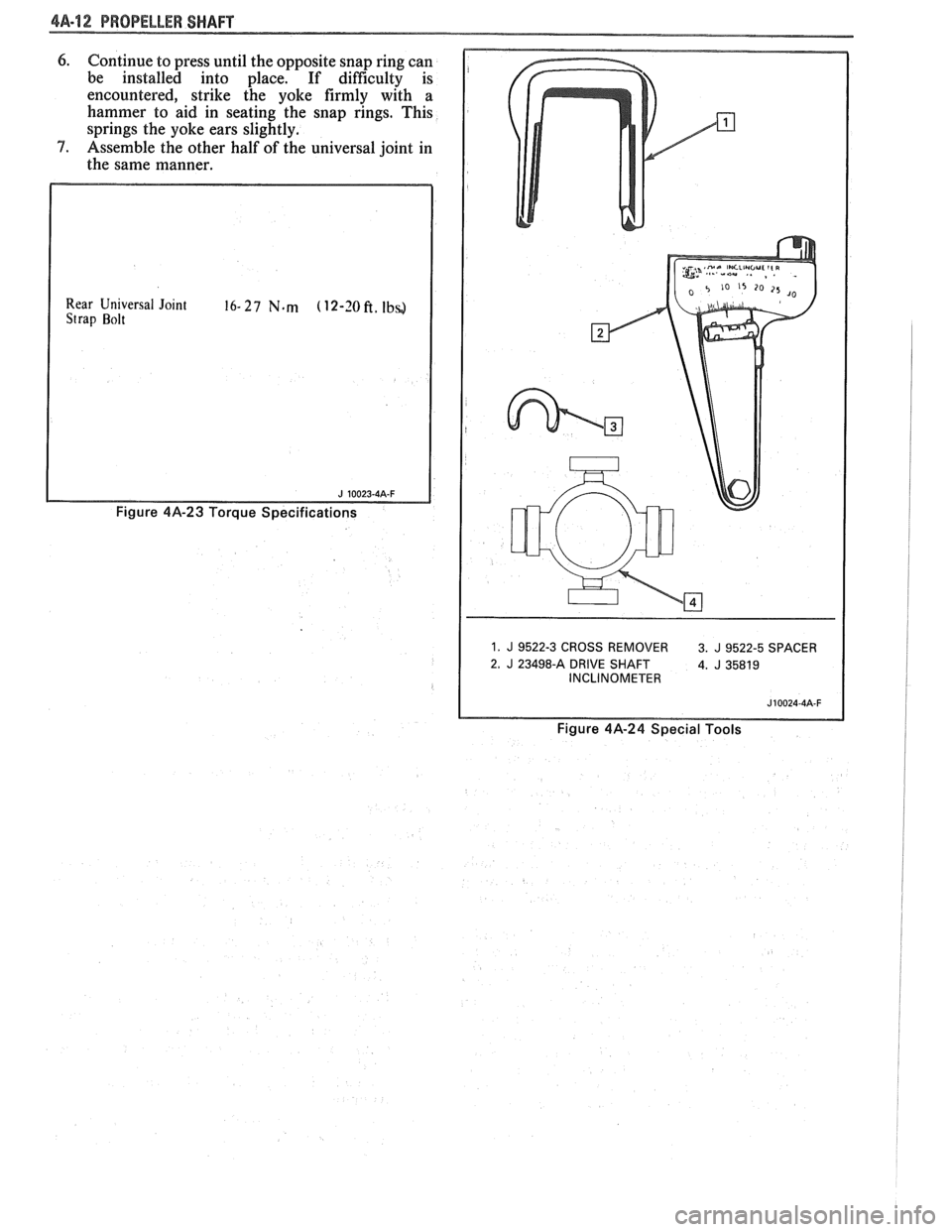
1. J 9522-3 CROSS REMOVER
3. J 9522-5 SPACER
2.
J 23498-A DRIVE SHAFT 4. J 35819
INCLINOMETER
Figure 4A-24 Special Tools