roof PONTIAC FIERO 1988 Service Owner's Guide
[x] Cancel search | Manufacturer: PONTIAC, Model Year: 1988, Model line: FIERO, Model: PONTIAC FIERO 1988Pages: 1825, PDF Size: 99.44 MB
Page 1766 of 1825
ROOF - F STYLE 8H-7
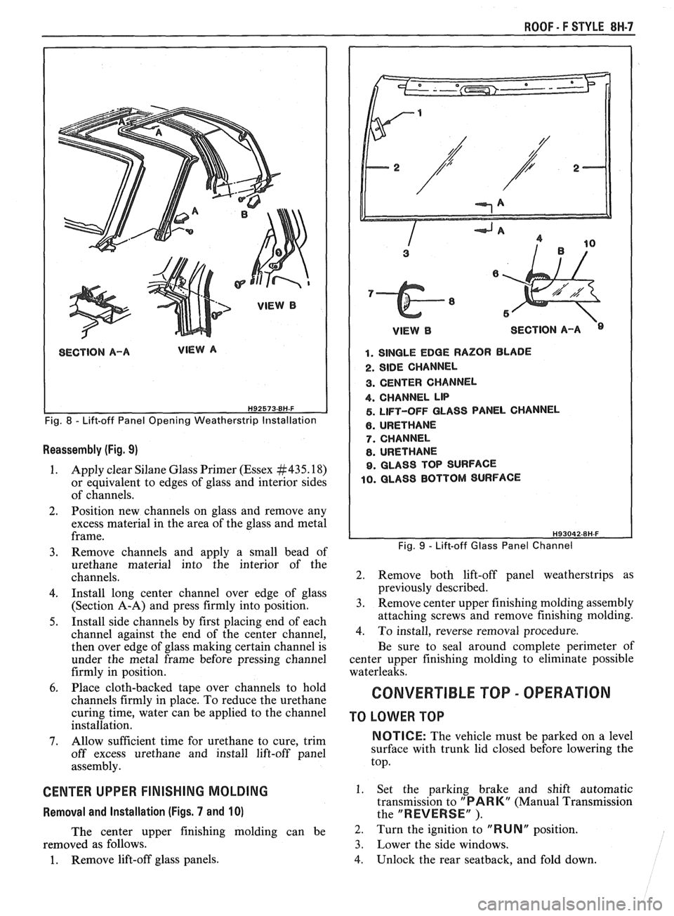
SECTION A-A VIEW A
Fig. 8 - Lift-off Panel Opening Weatherstrip Installation
Reassembly (Fig. 9)
1. Apply clear Silane Glass Primer (Essex #435.18)
or equivalent to edges of glass and interior sides
of channels.
2. Position new channels on glass and remove any
excess material in the area of the glass and metal
frame.
3. Remove channels and apply a small bead of
urethane material into the interior of the
channels.
4. Install long center channel over edge of glass
(Section A-A) and press firmly into position.
5. Install side channels by first placing end of each
channel against the end of the center channel,
then over edge of glass making certain channel is
under the metal frame before pressing channel
firmly in position.
6. Place cloth-backed tape over channels to hold
channels firmly in place. To reduce the urethane
curing time, water can be applied to the channel
installation.
7. Allow sufficient time for urethane to cure, trim
off excess urethane and install lift-off panel
assembly.
CENTER UPPER FINISHING MOLDING
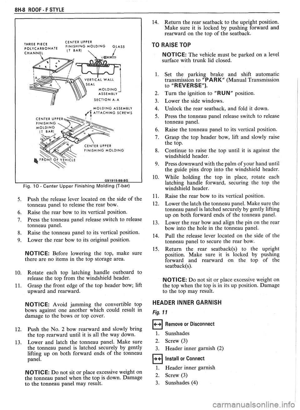
Removal and Installation (Figs. 7 and 10)
The center upper finishing molding can be
removed as follows.
1. Remove lift-off glass panels.
1 VlEWB SECTION A-A
1. SINGLE EDGE RAZOR BLADE
2. SIDE CHANNEL
3. CENTER CHANNEL
4. CHANNEL LIP
5. LIFT-OFF GLASS PANEL CHANNEL
6. URETHANE
7. CHANNEL
8. URETHANE
9. GLASS TOP SURFACE
10. GLASS BOTTOM SURFACE
Fig. 9 - Lift-off Glass Panel Channel
2. Remove both lift-off panel weatherstrips as
previously described.
3. Remove center upper finishing molding assembly
attaching screws and remove finishing molding.
4. To install, reverse removal procedure.
Be sure to seal around complete perimeter of
center upper finishing molding to eliminate possible
waterleaks.
CONVERTIBLE TOP - OPERATION
TO LOWER TOP
NOTICE: The vehicle must be parked on a level
surface with trunk lid closed before lowering the
top.
1. Set the parking brake and shift automatic
transmission to
"PARK" (Manual Transmission
the
"REVERSE" ).
2. Turn the ignition to "RUNN position.
3. Lower the side windows.
4. Unlock the rear seatback, and fold down.
Page 1767 of 1825
8H.8 ROOF - F STYLE
THREE PIECE CENTER
UPPER POLYCARBONATE FINISHING MOLDING GLASS (1 BAR)
CHANNEL 1
VERTICAL WALL
SECTION A-A
MOLDING ASSEMBLY
A ATTACHING SCREWS
Fig. 10 - Center Upper Finishing Molding (T-bar)
5. Push the release lever located on the side of the
tonneau panel to release the rear bow.
6. Raise the rear bow to its vertical position.
7. Press the tonneau panel release switch to release
tonneau panel.
8. Raise the tonneau panel to its vertical position.
9. Lower the rear bow to its original position.
NOTICE: Before lowering the top, make sure
there are no items in the top storage area.
10. Rotate
each top latching handle outboard to
release the top from the windshield header.
11. Grasp
the front edge of the top header bow; lift
upward and rearward.
N OTI C E: Avoid jamming the convertible top
bows against one another which could result in
damage to the bows or top cover.
12. Push the
No. 2 bow rearward and slowly bring
the top rearward until it is all the way down.
13. Lower
and latch the tonneau panel. Make sure
the tonneau panel is latched securely by gently
lifting up on both forward ends of the tonneau
panel.
NOTICE: Do not sit or place excessive weight on
the tonneau panel when the top is down. Damage
to the tonneau panel may result.
14. Return the rear seatback to the upright position.
Make sure it is locked by pushing forward and
rearward on the top of the seatback.
TO RAISE TOP
NOTICE: The vehicle must be parked on a level
surface with trunk lid closed.
1. Set the parking brake and shift automatic
transmission to
"PARK" (Manual Transmission
to
"REVERSE").
2. Turn the ignition to "RUN" position.
Lower the side windows.
Unlock the rear seatback, and fold it down.
Press the tonneau panel release switch to release
tonneau panel.
Raise the tonneau panel to its vertical position.
Grasp the top header bow, lift and slowly raise
the top.
Continue to raise the top until it is against the
windshield header.
Press downward with the palm of your hand until
the guide pins drop into the windshield header.
While holding the top in place, rotate each
latching handle forward, securing the top the
windshield header.
Raise the rear bow to its vertical position.
Lower the latch the tonneau panel. Make sure the
tonneau panel is latched securely by gently lifting
up on both forward ends of the tonneau panel.
Lower the rear bow and align the pin on the rear
bow into the hole in the tonneau panel.
Pull the release lever located on the side of the
tonneau panel to secure the rear bow.
Return the rear
seatback(s) to the upright
position. Make sure it is locked by pushing
forward and rearward on the top of the
seatback(s).
NOTICE: Do not sit or place excessive weight on
the top when the top is in its up position. Damage
to the top may result.
HEADER INNER GARNISH
Fig. 11
Remove or Disconnect
1. Sunshades
2. Screw (3)
3. Header inner garnish (2)
Install or Connect
1. Header inner garnish
2. Screw (3)
3. Sunshades
(4)
Page 1768 of 1825

ROOF - F STYLE 8H-9
"A" PILLAR INNER GARNISH
Fig. 1 Y
Remove or Disconnect
1. Screw (1)
2. "A" pillar inner garnish
Install or Connect
1. "A" pillar inner garnish
2. Screw
(1)
HEADER "A" PILLAR SEAL
Figs. 1 1 and 12
Remove or Disconnect
1.
Sunshades (4, Fig. 1 1)
2. Header inner garnish
3. Screws (1, Fig. 12)
4. Header "A" pillar seal (2). Grasp seal and pull
upward gently while inserting a flat-bladed tool
between seal retainer and seal to break cement
bond. Using a suitable release agent or heat gun
will aid in breaking the cement bond.
Install or Connect
MAIN PILLAR SEAL AND RETAINER
Fig. 13
Remove or Disconnect
1. Main
pillar seal using a suitable release agent or
heat gun, grasp seal and gently pull while
inserting a flat-bladed tool between seal and seal
retainer to break cement bond.
2. Screws (5) 3. Main pillar seal retainer
Install or Connect
1. Scrape excess sealer from seal retainer
2. Main pillar seal retainer
3. Screws (5)
4. Apply continuous bead of 3M Super
Weatherstrip Adhesive, part number 08008 or
equivalent, to the retainer channel.
5. Main pillar seal using a flat-bladed tool, engage
seal into retainer
NO. 5 BOW SEAL
Fig. 13
Remove or Disconnect
1. Scrape excess sealer from seal retainer. 1.
Main pillar seal and retainer (see procedure).
2. Apply continuous bead of 3M
Super
2. Screws(8) Weatherstrip Adhesive, part number 08008 or
equivalent,to the retainer channel. 3.
No.
5 bow seal using a suitable release agent or
3. Header "A" pillar seal (2, Fig. 12) using a heat
gun, grasp seal and gently pull while
flat-bladed tool, engage seal into retainer. inserting
a flat-bladed tool between seal and seal
retainer to break cement bond.
4. Screws (1)
5. Header inner garnish (2, Fig. 11) Install or Connect
6. Sunshades 1. Scrape excess sealer from seal retainer.
SIDE RAIL SEAL AND RETAINER
Fig. 13
2. Apply continuous bead of 3M Super
Weatherstrip Adhesive, part number 08008 or
equivalent, to the retainer channel.
3. No. 5 bow seal using a flat-bladed
tocul, engage a Remove or Disconnect seal into retainer.
1. Side rail seal using a suitable release agent or heat 4. Screws (8)
gun grasp seal and gently pull while inserting a 5, Main
pillar seal and retainer (see procedure).
flat-bladed tool between seal and seal retainer to
break cement bond.
NO. 1 BOW GARNISH MOLDING
2. No. 1 bow garnish molding (see procedure).
3. Screws (2) Fig. 14
4. Side rail seal retainer Remove or Disconnect
Install or Connect
1.
Release and raise No. 5 bow to its full vertical
1. Scrape excess sealer from seal retainer. position.
2. Side rail seal retainer. 2. Release and raise tonneau panel to its full vertical
position.
3. Screws
4. Apply cont~nuous bead of 3M Super 3. Lower the No. 5 bow to its original position.
Weatherstrip Adhesive, part number 08008 or 4. Unlatch the top from the windsl~ield header and
equivalent, to the retainer channel. lower
the top halfway.
5. Side rail seal using a flat-bladed tool, engage seal 5. Screws (1)
into retainer.
6. No. 1 bow garnish by pulling garnlsl~ down over
6. No. 1 bow garnish molding (see procedure). latch handles.
Page 1769 of 1825

8H-10 ROOF - F STYLE
VIEW B
Page 1770 of 1825

ROOF - F STYLE 8H-11
1. SCREW
2. HEADER "Ar' PILLAR SEAL
Fig. 12 "A" Pillar Sealer
gently pull while inserting a flat-bladed tool
between seal and seal retainer to break
cement bond.
14. Screws (5)
15. Main pillar seal retainer
16. Detach top cover quarter flaps from rear
rails (5, Fig. 15).
17. Pull side retention cables from top cover
side listing pockets.
18. Raise the top to the windshield header.
Then raise the No. 5 bow to its full vertical
position.
19. Screws (8, Fig. 13)
20. No. 5 bow seal using a suitable release
agent grasp seal and gently pull while
inserting a flat-bladed tool between seal and
seal retainer to break cement bond.
21. Detach top cover form No. 5 bow.
Install or Connect
lnstall or connect 1. Position top cover to framework.
1. No.
1 bow garnish by sliding garnish over latch
2. Insert No. 2 and No. 3 bow top cover retainers
handles into
top cover listing pockets.
2. Screws (1) 3. Insert side retention cables into top cover side
3. Latch
top to windshield header listing pockets.
A length of welding rod can be
used to pull cable through side listing pocket.
4. Raise
NO. 5 bow to full vertical position.
4. Raise top slightly off windshield header and
5. Lower
and latch tonneau panel
attach side retention cables to No. 1 bow with
6. Lower
and latch No. 5 bow to tonneau panel
screw.
TOP COVER ASSEMBLY
Figs. 13 through 16 6. 5.
Align
No. 2 and No. 3 bow top cover retainers to
No. 2 and No. 3 bows and secure with screws.
Remove or Disconnect 7.
1. Release
and raise the No. 5 bow to its full vertical
position.
2. Release and raise the tonneau panel to its full 8,
vertical position.
Lower the No. 5 bow to its original position. 9.
4. Unlatch the top
from the windshield header and
lower the top halfway.
10.
Screws (1, Fig. 14)
No. 1 bow garnish by pulling garnish down over
latch handles.
Screws (2, Fig. 13)
Side rail seal and retainer assemblies
Detach top cover and flaps from No. 1 bow.
Important
To aid in loosening top cover, heat can be
applied with a hot air gun held about 25 mm
(1 ") from top cover and rotated in a circular
motion to avoid overheating.
10. Screws securing side retention cables
1 1. Screws (3)
12. No. 2 and No. 3 bow top cover retainers
form listing pockets.
13. Main pillar seal using a suitable release
agent (Kent Special Release Agent or
equivalent or heat gun), grasp seal and Latch
top to windshield and align top cover
quarter flaps to rear rails.
Apply adhesive such as Hughes HC-4183, 3M
8046 or equivalent to cementing area or rear rails
and to corresponding surface of top cover quarter
flaps.
Position and secure top cover quarter flaps to rear
rails.
Raise No. 5 bow slightly and position top cover
to No. 5 bow.
Aling top cover center notch with No. 5 bow
--. latch pin.
Apply adhesive such as Hughes HC-4183, 3M
8046 or equivalent to cementing area of No. 5
bow and to corresponding surface of top cover.
Attach top cover to No. 5 bow, starting at center
working toward each outboard end.
Trim off all excess top material along No. 5 bow
- seal channel.
14. Apply continuous bead of 3M Super
Weatherstrip Adhesive, Part Number 08008 or
equivalent to the channel of the No. 5 bow.
15. No. 5 bow seal using flat-bladed tool, engage seal
into seal channel.
16. Screws (8)
17. Latch No. 5 bow to tonneau panel.
18. Pull top cover straight forward to seams over No.
1 bow to desired fullness.
19. While maintaining tension on top cover over top
No. 1 bow make pencil mark on cover outer
surface along forward edge of No. 1 bow.
Page 1772 of 1825

@ -
ROOF - F STYLE 8N-13
7. Rear stay pad and side stay pad from No. 4 bow
by sliding off.
Install or Connect
1. Side
stay pad and rear stay pad onto the No. 4
bow.
2. Screws
3. Rivet using
1/8" x 3/16" aluminum rivet.
4. Position side stay
pad to No. 1 bow and install
rivets using
1/8" x 3/16" aluminum rivets.
5. Tape (7)
6. With top
latched to windshield header and No.
Fig. 14 No. 1 Bow Garnish Molding 5 bow latched to tonneau panel, staple side stay
pad to No. 2 and No. 3 bows using 5/16" x 5/16"
stainless steel staplea. -
20. Release
and raise the tonneau panel to its full 7. Top cover assembly (see procedure). vertical position.
Release and raise the tonneau panel to its full
vertical position.
Lower the No,
5 bow to its original position.
Unlatch the top from
8-e windshield header and
lower the top halfway.
Apply adhesive such as Hughes HC-4183,
3M
8046 or equivalent to cementing area of No. 1
bow and to corresponding surface of top cover
and flaps.
Pull top cover 6 mm
(1/4") past reference mark
over No. 1 bow and secure top to No. 1 bow
starting at center working toward outboard ends.
Raise and latch top
*o windshield header and
latch No. 5 bow tu tonneau panel. Check
appearance of top cover, top
opeation and
latching effort to top. If additional tension is
needed in top cover, repeat step 25 and pull top
cover farther forward.
.
Trim off excess material along No. 1 bow.
Main pillar seal retainers.
Screws (5)
Apply continuous bead of 3M Super
Weatherstrip Adhesive, part number 08008 or
equivalent to the retainer channels.
Main pillar seals using a flat-bladed tool, engage
seal into retainer.
32. Side
rail seal and retainer assemblies
33. Screws (2)
34. No. 1
bow garnish by sliding garnish over latch
handles.
35. Screws (1)
SIDE STAY PAD
Fig. 15
Remove or Disconnect
1. Top cover assembly
2. Tape over rivets
3. Rivets using 3.2 mm (1/8") drill bit.
4. Staples from No. 2 and No. 3 bows. Note location
and. spacing of staples before removal.
5. Rivet
using 3.2 mm
(1/8") drill bit.
6. Screws
(1 1)
REAR STAY PAD
Fig. 17
Remove or Disconnect
1. Unlatch No. 5 bow and raise it to full vertical
position.
2. Rivet using
3.2 mm
(1/8") drill bit.
3. Screws (16)
4. Rear stay pad bracket
5. Screws (1 1)
6.
Rear stay pad by sliding stay pad off the end of
the No. 4 bow.
Install or Connect
1. Rear
stay pad to No. 4 bow.
2. Screws (1 1)
3. Rear stay pad bracket
4. Screws (16) 5. Rivet
using
1/8" x 3/16" aluminum rivet.
6. Lower No.
5 bow
and latch it to the tonneau
panel.
NO. 1 AND NO. 2 BOW ASSEMBLY
Figs. 13 through 17
Remove or Disconnect
Lower side windows
Unlock and fold down rear seatback.
Release No. 5 bow from tonneau panel, by
pushing release lever located on the side of
tonneau panel.
Raise No. 5 bow to full vertical position.
Release tonneau panel by pressing the tonneau
release switch and raise tonneau panel to full
vertical position.
Lower No. 5 bow to its original position.
Unlatch to top and lower it halfway.
Screws (1, Fig. 14)
No. 1 bow garnish by pulling garnish down over
latch handles.
Screws
(2, Fig. 13)
Side rail seal and setainer assemblies
Page 1773 of 1825

8H-14 ROOF - F STYLE
(1 ") from top cover and rotated in a circu,
motion to avoid overheating.
15. Screw securing side retention cables.
16. Side stay pads from No. 1 bow. Using a 3.2 mm
(1/8") drill bit, drill out rivets.
17. Side stay pads from No. 2 bow. Note location and
spacing of staples before removal.
18. Bolts (6, Fig. 17)
19. Bolts (5)
20. No. 1 and No. 2 bow assembly
Install or Connect
1.
No. 1 and No. 2 bow assembly
12. Screws (3, Fig. 15)
2. Bolts (5)
13. No. 2 bow top cover retainer from listing pocket. 3.
~olts (6) . .
14. Detach top
cover and flaps from No. 1 bow.
4. Side stay pad to No. 1 bow. Using 1/8" x 3/8"
aluminum rivets Important 5. Latch top to windshield header and staple side
To aid in loosening top cover heat can be
stay pads to No. 2 bow. Using 5/16"
x 5/16"
applied with a hot air gun held about 25 mm
stainless steel staples
Page 1775 of 1825

C
8H-16 ROOF - F STYLE
1. LATCH HANDLE
3. NO.
1 BOW 12.
NO. 5 BOW
4, NO. 2 BOW 13.
SCREW
14. RIVET
15. REAR STAY PAD
16. SCREW
17. REAR STAY PAD BRACKET
18. NO. 5 BOW PIN
10. NO. 4 BOW 19.
SCREW
Fig. 17 Top Stack
11. Apply adhesive such as Hughes HC-4183, 3M TOP STACK ASSEMBLY COMPLETE 8046 or equivalent to cementing area of No. 5
bow, to corresponding surface of top cover. Fig. 7 7
12. Position
and secure top cover to No. 5 bow, Remove or Disconnect
starting at center working toward outboard ends. Release and raise No, bow to its full vertical
position.
13. Scrape
excess adhesive from the channel of the
No.
5 bow. 2.
Release
and raise tonneau panel to its full vertical
position.
14. Apply continuous bead of
3M Super 3. Nuts (9)
Weatherstrip Adhesive, part number Ogoo8 Or 4. Unlatch the top from the windshield header. equivalent to the channel of the No. 5 bow. 5. With aid of helper, lift the complete top stack
15. No.
5 bow
seal using a flat-bladed tool, engage assembly
from car.
seal into seal channel.
Install or Connect
16. Screws attaching seal to rear rail. 1. Position the top stack assembly to body
2. Latch top to windshield header
17. Lower
No.
5 bow and latch it to the tonneau
panel.
3. Nuts(9)
4. Lower and latch tonneau panel then lower and
18. Main
pillar seal and retainer (see procedure) latch
No. 5 bow
Page 1776 of 1825

ROOF - F STYLE 8H-17
a Inspect
Top stack assembly fit to body.
Adjust
Top stack as necessary by loosening nuts
and shifting top stack
6. Tighten nuts to 10
Nem (13 ft-lbs)
QUARTER INNER UPPER TRlM CAP
Fig. 18
Remove or Disconnect
1. Lower top completely.
2. Screws
(2)
3. Quarter
inner upper trim cap and bezel
Install or Connect
.. Quarter inner upper trim cap and bezel
2. Screws (2)
QUARTER TRlM PANEL
Fig. 18
Remove or Disconnect
1. Rear seat cushion
2. Sill
plate and carpet retainer
3. Quiarter inner upper trim cap
4. Lock pillar finish molding
5. Screws
6. Pull quarter trim panel out and disconnect
speaker wire connector
7. Push seat belt through slot in trim panel
8. Quarter trim panel
Install or Connect
.. Position quarter trim panel to body. Thread seat
belt through slot in trim panel and connect wire
connector to speaker.
2. Screws
3. Lock pillar finish molding
4. Quarter
inner upper tirm cap
5. Sill plate and carpet retainer
6. Rear seat cushion
QUARTER CAP BELT MOLDING
Fig. 19
The quarter cap belt moldings are attached to the
body by screws and adhesive tape shown in Figure 19.
The quarter cap belt molding can be removed from the
body with the use of a hot air gun to break the adhesive
tape bond.
Important
When removing or installing quarter cap
belt molding, care should be exercised.
Adjacent finishes should be protected to
prevent damage to finish.
e Proper tools and care should be used to
guard against molding damage.
Remove or Disconnect
1.
Quarter inner upper trim cap
2. Screws (1)
3. Quarter cap belt molding using hot air gun held
about 300 mm (12") from the surface. Apply heat
in a circular motion and carefully lift the molding
from the body surface.
e Wash quarter panel area with soap and
water and wipe dry.
Wipe quarter panel and adhesive side of
molding with a clean rag using oil-free
Naptha or alcohol to remove all traces of
adhesive tape from quarter panel and back
side of molding.
Install or Connect
1.
Apply a double-coated adhesive tape such as 3M
Super Automotive Attachment Tape (Part
Number 4210) or equivalent to the molding.
2. Quarter cap belt molding warm quarter panel
with heat lamp or heat gun about 21°C (70°F).
Align molding and press firmly in place.
3. Screws (1)
4. Quarter inner trim cap (see procedure)
TONNEAU PANEL LATCH
Fig, 20
Remove or Disconnect
1. Quarter trim panel (see procedure)
2. Cable (1)
3. Screws (3)
4. Latch (4)
Install or Connect
1. Latch (4)
2. Screws (3)
3. Cable (1)
4. Quarter trim panel (see procedure)
Important
Latch as required and retighen screws.
TONNEAU RELEASE SOLENOID
Fig, 20
Remove or Disconnect
1. Quarter trim panel (see procedure)
2. Cable from latch p
3. Wire connector (6)
4. Screws (7)
5. Solenoid (8)
Page 1777 of 1825

8H-18 ROOF - F STYLE
1. QUARTER INNER UPPER TRlM CAP
2. SCREW
3. SEAT BELT BEZEL
4. LOCK PILLAR FINISH MOLDING
5. SCREW
6. QUARTER TRlM PANEL
Fig. 18 Quarter Inner Upper Trim