dimensions PONTIAC FIERO 1988 Service Repair Manual
[x] Cancel search | Manufacturer: PONTIAC, Model Year: 1988, Model line: FIERO, Model: PONTIAC FIERO 1988Pages: 1825, PDF Size: 99.44 MB
Page 11 of 1825
08-8 GENERAL INFORMATION
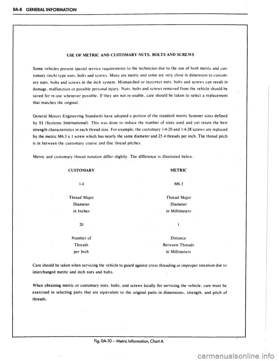
USE OF METRIC AND CUSTOMARY NUTS, BOLTS AND SCRERS
Some veh~cles present spec~al servlce requ~rements to the technrc~a~l due to the use of both metnc and cus-
tomary
(Inch) type nuts, bolt5 and screws. Many are metnc and some are very close in d~mens~on to custom-
ary nuts. bolts and screws in the
Inch system M~smatched or Incorect nut5, bolt5 and screus can result rn
damage, malfunct~on or poss~ble personal Injury Nuts. bolts and screws removed from the veh~cle 5hould be
saved for re-use
uhenever poscrble. If they are not re-usable. care should be taken to select a replacement
that matches the
ong~nal.
General Motors Eng~neenng Standards have ddopted a portion of the standard metnc fastener slzes defined
by SI (Systeme
Internatronal) Th~s was done to reduce the number of srzes used and yet retarn the best
strength
character~st~cs In each thtead size. For example. the customary 114-20 and 1/4-28 screws are replaced
by the
metrlc M6.3 x I screw wh~ch has nearly the same d~ameter and 25.4 threads per inch. The thread p~tch
IS In between the customary coarse and fine thread prtches.
Metnc and customary thread notatlon d~ffer sl~ghtly. The d~fference IS ~llustrated belou.
CUSTOMARY METRIC
Thread Major Thread Major
D~ameter D~ameter
~n inches rn M~ll~meters
Number of D~stance
Threads Between Threads
in Mill~meters
Care should be taken when servlclng the veh~cle to guard agalnst cross thread~ng or Improper retention due to
interchanged metnc and inch nuts and bolts.
When
obtarn~ng metnc or customary nuts, bolts, and screws locally for servrcing the vehicle. care must be
exerc~sed in selecting parts that are equrvalent to the ong~nal parts In dimensions. strength. and p~tch of
Fig. OA-10 -- Metric Information, Chart A
Page 146 of 1825
STEERING, SUSPENSION. TIRES AND WHEELS DIAGNOSIS 3-21
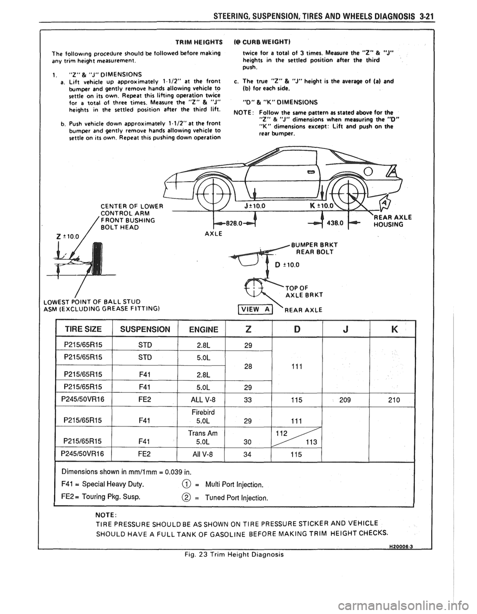
TRIM WEIGHTS (@ CURB WEIGHT) I
The follow~ng procedure should be followed before making
any trim height measurement.
1.
"2" & "J" DIMENSIONS a. Lift vehicle up approximately 1-112" at the front
bumper and gently remove hands allowing vehicle to
settle on its own. Repeat this lifting operation twice
for
a total of three times. Measure the "2" & "J" heights in the settled position after the third lift.
b. Push vehicle down approximately
1.1/2"at the front
bumper and gently remove hands allowing vehicle to
settle on its own. Repeat this pushing down operation twice for
a total
of 3 times. Mewre the "Z" & "J" heights in the settled position after the third
push.
c. The true
"2" L "J" height is the averlge of (a) and (b) for each side.
"0" L "K" DIMENSIONS
NOTE
: Follow the same pattern cn stated above for the "Z" & "J" dimensions when measuring the "0" "K" dimensions except: Lift and push on the
rear bumper.
CENTER OF
LOWE CONTROL ARM 'FRONT BUSHING BOLT HEAD k828.0-t REAR AXLE
Z '10.0 / AXLE
BUMPER BRKT
REAR BOLT
ASM (EXCLUDING GREASE FITTING)
I Dimensions shown in mmll mm = 0.039 in. I
F41 = Special Heavy Duty. = Multi Port Injection.
FE2 = Touring Pkg. Susp.
NOTE:
TIRE PRESSURE
SHOULDBE AS SHOWN ON TIRE PRESSURE STICKER AND VEHICLE
SHOULD HAVE A
FULLTANK OF GASOLINE BEFORE MAKING TRIM HEIGHT CHECKS.
I Fig. 23 Trim Height Diagnosis
Page 151 of 1825
3A-4 WHEEL ALIGNMENT
AXLE HOUSING ALIGNMENT 2. If a tram is used for checking toe out, it will still
be necessary to perform Steps
1 and 2 in order to If rear tire wear indicates that the axle housing
check camber.
may be bent, the alignment can be checked as follows:
The necessary straightening operations may be
1. Back the car squarely onto an alignment performed using frame straightening equipment
machine, ~h~ actual toe-out will be read on the without removing the axle housing from the car. This
scale as toe-in. However, if the toe-out is checked procedure will allow checks during the straightening
with a tram gage, disregard this notice. operation
to determine when the housing is within the
prescribed limits.
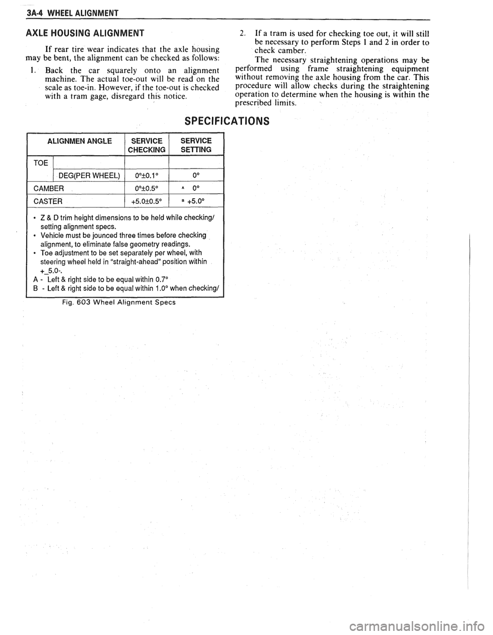
SPECIFICATIONS
1 CASTER 1 +5.0+0.5O 1 +5.0° 1
TOE
* Z & D trim height dimensions to be held while checking1
setting alignment specs.
* Vehicle must be jounced three times before checking
alignment, to eliminate false geometry readings.
Toe adjustment to be set separately per wheel, with
steering wheel held in "straight-ahead" position within
+-5.0-.
A - Left & right side to be equal within 0.7"
B - Left & right side to be equal within 1 .OO when checking1
Fig. 603 Wheel Alignment Specs
DEG(PER WHEEL)
CAMBER OO+O.10 0°
O0+O.5O A 0°
Page 232 of 1825
TIRES AND WHEELS 3E-1
RES AND WHEELS
NOTICE: All wheel bolt and nut fasteners are important attaching parts in that they could affect the
performance of vital components and systems, and/or could result in major repair expense. They must be replaced
with one of the same part number or with an equivalent part if replacement becomes necessary. Do not use a
replacement part of lesser quality or substitute design. Torque values must be used as specified during reassembly
to assure proper retention of parts.
CONTENTS
Diagnosis ............................................... Section 3 Tire Repair ................................................... 3E-5
General Information .......................... ..... 3E-1 Waddle ........................................................ 3E-5
........ Replacement Tires ....................... ... 3E- 1 Measuring Wheel Runout ............................ 3E-6
P-Metric Tires ...................... .. ................... 3E-2 Spare Tire ...................................................... 3E-6 ................................................ Tire Placard 3E-2 Match Mounting ......................................... 3E-7
.......................................................... Wheels 3E-2 Balancing Tire and Wheel ............................ 3E-7
....................... Maintenance and Adjustments .............. 3E-2 General Balance Precautions 3E-7 ...................................... Wheel Repair .............................................. 3E-2 Off-Car Balancing 3E-8 .............................. Metric Wheel Nuts and Studs .................... .. 3E-3 On-Car Balancing .. ...... 3E-8
......................................... Inflation of Tires ........................................ 3E-3 Wheel Weights 3E-8 .................... Tire Rotation ........................... ...... . 3E-3 Correcting Non-Uniform Tires 3E-8 .......................... Tire Chain Usage ........................................ 3E-4 Aluminum Wheel Cleaning 3E-9 Aluminum Wheel Hub Cap ......................... 3E-9 Service Operations ..................................... 3E-4 Aluminum Wheel Porosity Repair .............. 3E-9 ......................... Wheel Removal .... .......... 3E-4 Aluminum Wheel Refinishing ...................... 3E-9 Tire Mounting and Dismounting ................. 3E-5 Wheel Nut Torque 3E-10 ......................................
GENERAL INFORMATION ~t is recommended that new tires be installed in
pairs on the same axle. If it is necessary to replace only
The tires and are one tire, it should be paired with the tire having the
designed to operate satisfactorily with loads up to and
most tread, to equalize braking traction. including the full rated load capacity when inflated to
Although they may appear different in tread
the recommended inflation pressures.
design, tires built by different manufacturers with
Correct tire pressures, wheel alignment and identical TPC specification numbers, can be
driving techniques have an important influence on tire
intermixed on the same car. life. Heavy cornering, excessive rapid acceleration, and
heavy braking will increase tire wear.
REPLACEMENT TIRES
Fig. 1
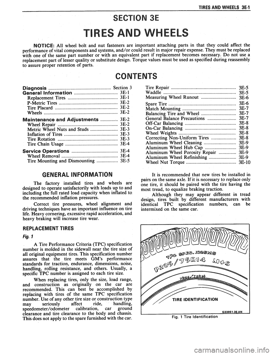
A Tire Performance Criteria (TPC) specification
number is molded in the sidewall near the tire size of
all original equipment tires. This specification number
assures that the tire meets
GM's performance
standards for traction, endurance, dimensions, noise,
handling, rolling resistance, and others. Usually, a
specific TPC number is assigned to each tire size.
When replacing tires, only the size, load range,
and construction as originally on the car are
recommended. This can best be accomplished by
replacing with tires of the same TPC specification
number. Use of any other tire size or construction type
may seriously affect ride, handling,
speedometer/odometer calibration, car ground
clearance and tire clearance to the body and chassis.
This does not apply to the spare furnished with the car.
v// TIRE IDENTIFICATION
Fig. 1 Tire Identification
Page 377 of 1825
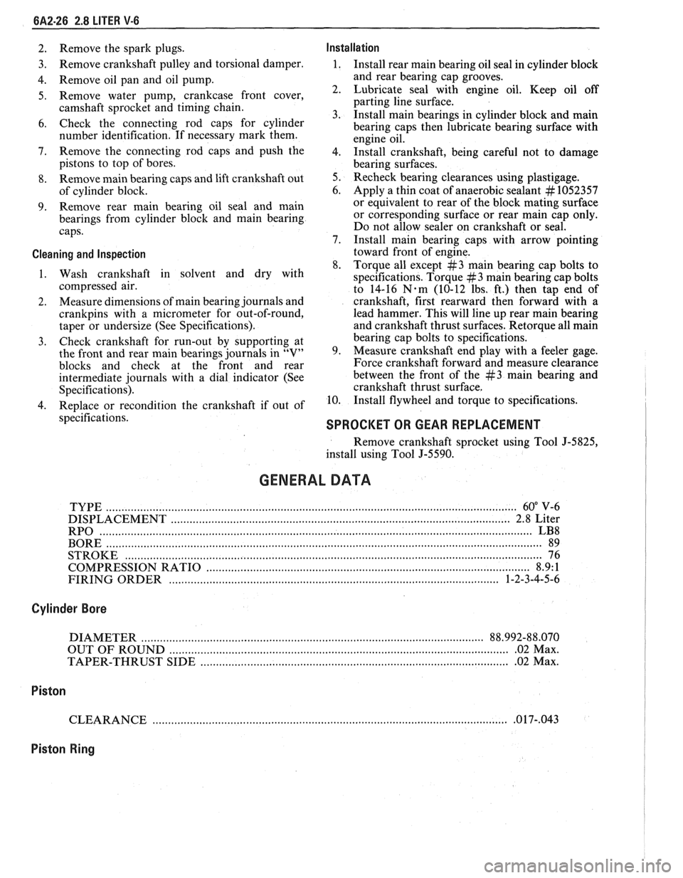
6A2-26 2.8 LITER V-6
2. Remove the spark plugs. Installation
3. Remove
crankshaft pulley and torsional damper. 1. Install rear main bearing oil seal in cylinder block
4. Remove oil pan and oil pump. and
rear bearing cap grooves.
5. Remove water pump, crankcase front cover, 2. Lubricate seal with engine oil. Keep oil off
camshaft sprocket and timing chain. parting
line surface.
3. Install main bearings in cylinder block and main
6. Check the connecting rod caps for cylinder
bearing caps then lubricate bearing surface with
number identification. If necessary mark them.
engine oil.
7. Remove the connecting rod caps and
push the
4. 1n;tall crankshaft, being careful not to damage
pistons to top of bores.
bearing surfaces.
8. Remove main bearing caps and lift crankshaft out 5. Recheck bearing clearances using plastigage.
of cylinder block. 6.
Apply a thin coat of anaerobic sealant
# 1052357
9. Remove rear
main bearing oil seal and main or
equivalent to rear of the block mating surface
bearings from cylinder block and main bearing or corresponding
surface or rear main cap only.
caps. Do
not allow sealer on crankshaft or seal.
7. Install main bearing caps with arrow pointing
Cleaning and Inspection toward front of engine.
8. Torque all except
#3 main bearing cap bolts to
1. Wash crankshaft in solvent and dry with
specifications. Torque
#3 main bearing cap bolts
compressed air. to 14-16
N-m (10-12 lbs. ft.) then tap end of
2. Measure
dimensions of main bearing journals and crankshaft, first rearward then forward with a
crankpins with a micrometer for out-of-round, lead
hammer. This will line up rear main bearing
taper or undersize (See Specifications). and crankshaft
thrust surfaces.
Retorque all main
3. Check
crankshaft for run-out by supporting at bearing
cap bolts to specifications.
the front and rear main bearings journals in "V" 9. Measure crankshaft
end play with a feeler gage.
blocks and check at the front and rear Force crankshaft forward and measure clearance
intermediate journals with a dial indicator (See between the front of the
#3 main bearing and
Specifications). crankshaft thrust surface.
4. Replace or recondition the crankshaft if out of 10.
Install flywheel and torque to specifications.
specifications.
SPROCKET OR GEAR REPLACEMENT
Remove crankshaft sprocket using Tool J-5825,
install using Tool J-5590.
GENERAL DATA
TYPE .................................................................................................................................... 60" V-6
DISPLACEMENT
............................................................................................................. 2.8 Liter
RPO
........................................................................................................................................... LB8
BORE ......................................................................................................................................... 89
STROKE
................................... .... ............................................................................................... 76
COMPRESSION RATIO
....................................................................................................... 8.9: 1
FIRING ORDER
.......................................................................................................... 1-2-3-4-5-6
Cylinder Bore
DIAMETER .............................................................................................................. 88.992-88.070
OUT OF ROUND
............................................................................................................. .02 Max.
TAPER-THRUST SIDE
................................................................................................. .02 Max.
Piston
CLEARANCE .................................................................................................................. .O 17-,043
Piston Ring
Page 407 of 1825
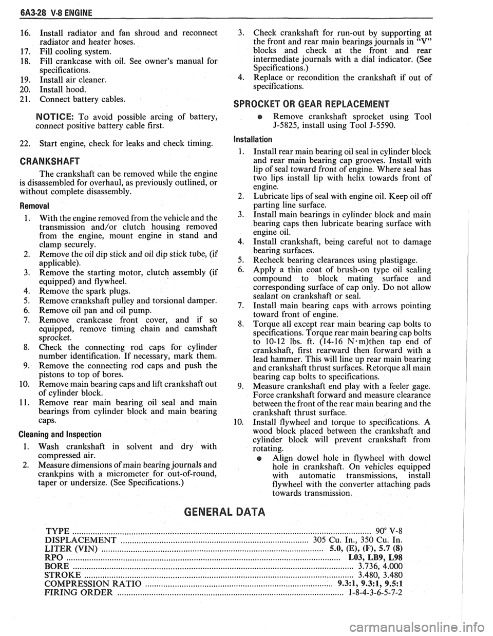
6A3-28 V-8 ENGINE
16. Install
radiator and fan shroud and reconnect
radiator and heater hoses.
17. Fill cooling system.
18. Fill
crankcase with oil. See owner's manual for
specifications.
19. Install air cleaner.
20. Install hood.
21. Connect battery cables.
NOTICE: To avoid possible arcing of battery,
connect positive battery cable first.
22. Start engine, check for leaks and check timing.
CRANKSHAFT
The crankshaft can be removed while the engine
is disassembled for overhaul, as previously outlined, or
without complete disassembly.
Removal
With the engine removed from the vehicle and the
transmission and/or clutch housing removed
from the engine, mount engine in stand and
clamp securely.
Remove the oil dip stick and oil dip stick tube, (if
applicable).
Remove the starting motor, clutch assembly (if
equipped) and flywheel.
Remove the spark plugs.
Remove crankshaft pulley and torsional damper.
Remove oil pan and oil pump.
Remove crankcase front cover, and if so
equipped, remove timing chain and camshaft
sprocket.
Check the connecting rod caps for cylinder
number identification. If necessary, mark them.
Remove the connecting rod caps and push the
pistons to top of bores.
Remove main bearing caps and lift crankshaft out
of cylinder block.
Remove rear main bearing oil seal and main
bearings from cylinder block and main bearing
caps.
Cleaning and Inspection
1. Wash crankshaft in solvent and dry with
compressed air.
2. Measure dimensions of main bearing journals and
crankpins with a micrometer for out-of-round,
taper or undersize. (See Specifications.) 3.
Check crankshaft for run-out by supporting at
the front and rear main bearings journals in
"V"
blocks and check at the front and rear
intermediate journals with a dial indicator. (See
Specifications.)
4. Replace or recondition the crankshaft if out of
specifications.
SPROCKET OR GEAR REPLACEMENT
e Remove crankshaft sprocket using Tool
5-5825, install using Tool J-5590.
Installation
1.
Install rear main bearing oil seal in cylinder block
and rear main bearing cap grooves. Install with
lip of seal toward front of engine. Where seal has
two lips install lip with helix towards front of
engine.
2. Lubricate lips of seal with engine oil. Keep oil off
parting line surface.
3. Install main bearings in cylinder block and main
bearing caps then lubricate bearing surface with
engine oil.
4. Install crankshaft, being careful not to damage
bearing surfaces.
5. Recheck bearing clearances using plastigage.
6. Apply a thin coat of brush-on type oil sealing
compound to block mating surface and
corresponding surface of cap only. Do not allow
sealant on crankshaft or seal.
7. Install main bearing caps with arrows pointing
toward front of engine.
8. Torque all except rear main bearing cap bolts to
specifications. Torque rear main bearing cap bolts
to 10-12 lbs. ft. (14-16
N.m)then tap end of
crankshaft, first rearward then forward with a
lead hammer. This will line up rear main bearing
and crankshaft thrust surfaces.
Retorque all main
bearing cap bolts to specifications.
9. Measure crankshaft end play with a feeler gage.
Force crankshaft forward and measure clearance
between the front of the rear main bearing and the
crankshaft thrust surface.
10. Install flywheel and torque to specifications. A
wood block placed between the crankshaft and
cylinder block will prevent crankshaft from
rotating.
Align dowel hole in flywheel with dowel
hole in crankshaft. On vehicles equipped
with automatic transmissions, install
flywheel with the converter attaching pads
towards transmission.
GENERAL DATA
TYPE .................................................................................................................................. 90" V-8
DISPLACEMENT
............................................................................... 305 Cu. In., 350 Cu. In.
......................................................... LITER (VIN) ................................... ...... 5.0, (E), (F), 5.7 (8)
RPO ......................................................................................................................... L03, LB9, L98
BORE ........................................................................................................................ 3.736, 4.000
STROKE
........................... .. ....................................................................................... 3.480, 3.480
COMPRESSION RATIO
................................................................................... 931, 931, 9.5:1
FIRING ORDER .................................................................................................... 1-8-4-3-6-5-7-2
Page 1072 of 1825
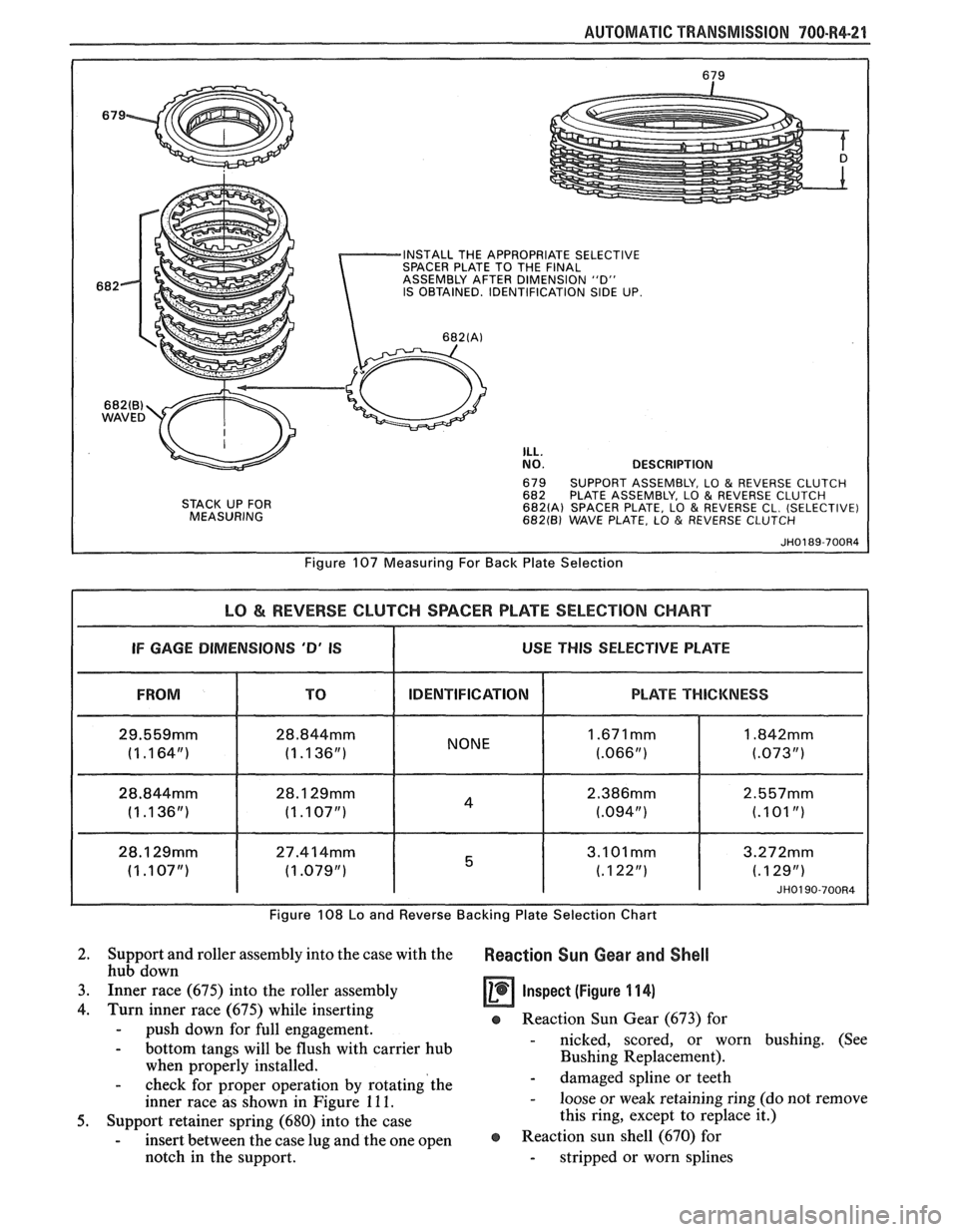
AUTOMATIC TRANSMISSION 700.R4-21
INSTALL THE APPROPRIATE SELECTIVE
SPACER PLATE TO THE FINAL
ASSEMBLY AFTER DIMENSION "D"
IS OBTAINED. IDENTIFICATION
SIDE UP.
682(B) WAVED
STACK UP FOR
MEASURING
ILL. NO. DESCRIPTION
679 SUPPORT ASSEMBLY, LO & REVERSE CLUTCH
682 PLATE ASSEMBLY, LO & REVERSE CLUTCH 682(A) SPACER PLATE, LO & REVERSE CL. (SELECTIVE) 682(B) WAVE PLATE, LO & REVERSE CLUTCH
Figure 107 Measuring For Back Plate Selection
LO & REVERSE CLUTCH SPACER PLATE SELECTION CHART
I IF GAGE DIMENSIONS 'D' IS I USE THIS SELECTIVE PLATE I
FROM IDENTIFICATION
28.844mm
(1 .I 36") I NONE
Figure 108 Lo and
Reverse Backing Plat
PLATE THICKNESS
JH0190-700R4
? Selection Chart
2. Support and roller assembly into the case with the Reaction Sun Gear and Shell hub down
3. Inner race (675) into the roller assembly
Inspect (Figure 11 4)
4. Turn inner race (675) while inserting e Reaction Sun Gear (673) for - push down for full engagement.
- bottom tangs will be flush with carrier hub - nicked, scored, or worn bushing. (See
when properly installed. Bushing Replacement).
- check for
proper operation by rotating'the - damaged spline or teeth
inner race as shown in Figure
11 1. - loose or weak retaining ring (do not remove
5. Support retainer spring (680) into the case this
ring, except to replace it.)
- insert between the case lug and the one open @ Reaction sun shell (670) for
notch in the support. - stripped or worn splines
Page 1640 of 1825
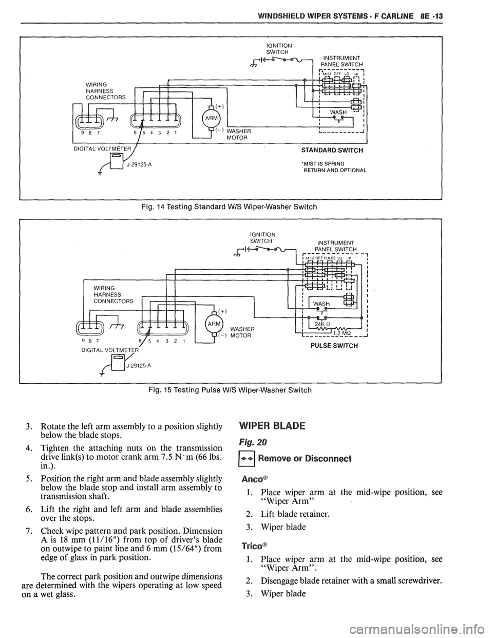
WINDSHIELD WIPER SYSTEMS - F CARLINE 8E -13
'MIST IS SPRING
RETURN AND OPTIONAL
Fig. 14 Testing Standard WIS Wiper-Washer Switch
Fig.
15 Testing Pulse WIS Wiper-Washer Switch
3. Rotate the left arm assembly to a position slightly
below the blade stops.
4. Tighten the attaching nuts on the transmission
drive
link(s) to motor crank arm 7.5 N'm (66 lbs.
in.).
5. Position the right arm and blade assembly slightly
below the blade stop and install arm assembly to
transmission shaft.
6. Lift the right and left arm and blade assemblies
over the stops.
7. Check wipe pattern and park position. Dimension
A is 18 mm (1 1/16") from top of driver's blade
on
outwipe to paint line and 6 mm (15/64") from
edge of glass in park position.
The correct park position and
outwipe dimensions
are determined with the wipers operating at low speed
on a wet glass.
WIPER BLADE
Fig. 20
Remove or Disconnect
Anso@
1. Place wiper arm at the mid-wipe position, see
"Wiper Arm"
2. Lift blade retainer.
3. Wiper blade
TY~GO@
1. Place wiper arm at the mid-wipe position, see
"Wiper Arm".
2. Disengage blade retainer with a small screwdriver.
3. Wiper blade
Page 1701 of 1825
2H-4 STATIONARY GLASS - F STYLE
7. Watertest car at once using soft spray. Use warm
or hot water if available. Do not direct hard
stream of water at fresh adhesive material. If any
leaks are found, paddle in extra adhesive at leak
point using a small disposable brush or
flat-bladed tool. Water applied on top of urethane
adhesive, either during watertest or as a separate
operation, will speed up the cure of the urethane.
8. Install windshield reveal molding.
9. Install
all other previously removed parts and
clean up.
10. On windshield installations, car must remain at
normal room temperature for six hours to
complete proper cure of adhesive.
Extended Method
It will be necessary to use extended installation
method if prior service installation was made with
butyl tape or if urethane material remaining in window
opening after window removal is damaged, or must be
removed to permit refinishing of window opening.
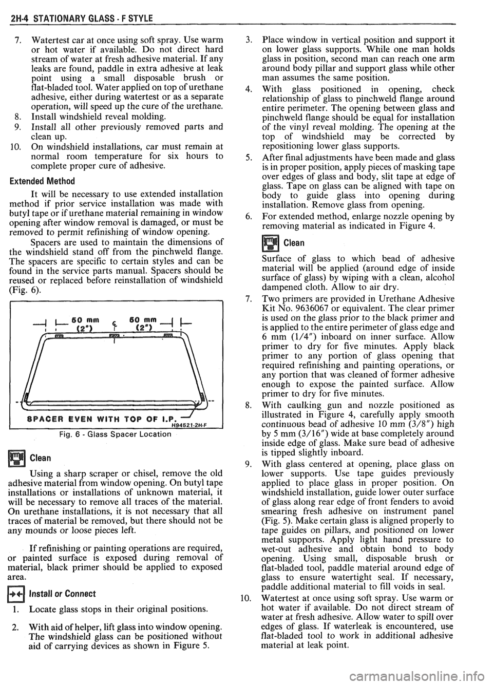
Spacers are used to maintain the dimensions of
the windshield stand off from the pinchweld flange.
The spacers are specific to certain styles and can be
found in the service parts manual. Spacers should be
reused or replaced before reinstallation of windshield
(Fig. 6).
Fig. 6 - Glass Spacer Location
Using a sharp scraper or chisel, remove the old
adhesive material from window opening. On butyl tape
installations or installations of unknown material, it
will be necessary to remove all traces of the material.
On urethane installations, it is not necessary that all
traces of material be removed, but there should not be
any mounds or loose pieces left.
If refinishing or painting operations are required,
or painted surface is exposed during removal of
material, black primer should be applied to exposed
area.
Install or Connect
1. Locate glass stops in their original positions.
2. With aid of helper, lift glass into window opening.
The windshield glass can be positioned without
aid of carrying devices as shown in Figure 5. Place window
in vertical position and support it
on lower glass supports. While one man holds
glass in position, second man can reach one arm
around body pillar and support glass while other
man assumes the same position.
With glass positioned in opening, check
relationship of glass to pinchweld flange around
entire perimeter. The opening between glass and
pinchweld flange should be equal for installation
of the vinyl reveal molding. The opening at the
top of windshield may be corrected by
repositioning lower glass supports.
After final adjustments have been made and glass
is in proper position, apply pieces of masking tape
over edges of glass and body, slit tape at edge of
glass. Tape on glass can be aligned with tape on
body to guide glass into opening during
installation. Remove glass from opening.
For extended method, enlarge nozzle opening by
removing material as indicated in Figure
4.
Clean
Surface of glass to which bead of adhesive
material will be applied (around edge of inside
surface of glass) by wiping with a clean, alcohol
dampened cloth. Allow to air dry.
Two primers are provided in Urethane Adhesive
Kit No. 9636067 or equivalent. The clear primer
is used on the glass prior to the black primer and
is applied to the entire perimeter of glass edge and
6 mm
(1/4") inboard on inner surface. Allow
primer to dry for five minutes. Apply black
primer to any portion of glass opening that
required refinishing and painting operations, or
any portion that was cleaned of former adhesive
enough to expose the painted surface. Allow
primer to dry for five minutes.
With caulking gun and nozzle positioned as
illustrated in Figure 4, carefully apply smooth
continuous bead of adhesive 10 mm
(3/8") high
by 5 mm
(3/16") wide at base completely around
inside edge of glass. Make sure bead of adhesive
is tipped slightly inboard.
With glass centered at opening, place glass on
lower supports. Use tape guides previously
applied to place glass in proper position. On
windshield installation, guide lower outer surface
of glass along rear edge of front fenders to avoid
smearing fresh adhesive on instrument panel
(Fig. 5). Make certain glass is aligned properly to
tape guides on pillars, and positioned on lower
metal supports. Apply light hand pressure to
wet-out adhesive and obtain bond to body
opening. Using small, disposable brush or
flat-bladed tool, paddle material around edge of
glass to ensure watertight seal. If necessary,
paddle additional material to fill voids in seal.
Watertest at once using soft spray. Use warm or
hot water if available. Do not direct stream of
water at fresh adhesive. Allow water to spill over
edges of glass. If waterleak is encountered, use
flat-bladed tool to work in additional adhesive
material at leak point.
Page 1706 of 1825
UNDERBODY-F STYLE 3H-1
SECTION 3H
UNDERBODY
CONTENTS
General Body Construction .......................................................................................................... 3H- 1
Alignment Checking ................................................................................................................ 3H- I
Floor Pan Insulators ...................... .. ........................................................................................ 3H- 1
Floor Carpets ................................................................................................................................. 3H-2
metric-to-English dimensional conversion data.
Dimensions to gage holes are measured to dead center
GENERAL BODY CONSTRUCTION of the holes and flush to adjacent surface metal unless
Information in this section pertains to unitized otherwise specified.
body construction which
incorporates integral front
and rear frame side rails. FLOOR PAN INSULATORS
Consideration must be given when checking
underbody dimensions. The engine front suspension
lower control arms are supported by a cross member.
The cross member, in turn, is bolted to the body at six
locations
-- three on each side of the engine front
compartment lower rails. Mounting provisions for the
front suspension system are shared by chassis
components (suspension lower control arms and cross
member) and body components (engine compartment
side panels). The suspension strut towers must be
dimensionally correct in relation to the remainder of
the underbody in order to maintain specified
suspension strut and
castedcamber angles.
Since the individual underbody components also
contribute directly to the overall strength of the body,
it is essential that proper welding techniques be
observed during service repair operations. The
underbody components should be properly sealed and
rustproofed whenever body repair operations destroy
or damage the original sealing and rustproofing. When
rustproofing critical underbody components, it is
essential that a good quality type of air dry primer be
used (such as corrosion resistant chromate or
equivalent material). It is not advisable to use
combination type primer-surfacers.
ALIGNMENT CHECKING
An accurate method of determining the
alignment of the underbody utilizes a measuring tram
gage. The tram gage set required to perform the
recommended measuring checks must include a
vertical pointer capable of reaching 914 mm (36").
Two types of measurements can be made with
a
tram gage: direct point-to-point measurements and
measurements calculated on a horizontal
vlane (datum
line) parallel to the underbody. In the
latter case, the
vertical pointers must be set as specified for each point
to be measured (Fig. 3-1).
Point-to-point measurements are generally taken
only on engine compartment components (Fig. 3-2)
and simply require the vertical pointers to be equally
set.
Figure #3-3 describes the alphabetically
identified points of measurement. Figure 3-4 provides Floor
pan insulators have been designed for the
higher floor pan temperatures that result from the use
of the catalytic converter in the exhaust system.
Therefore, when servicing a vehicle in the field, it is
essential that any insulators that may have been
disturbed or removed be reinstalled in the original
sequence and location. Also, if it becomes necessary to
replace an insulator, the material specified for that
particular location on the floor pan must be used. The
types of materials are listed below. Items 1 and
2 are
rolled stock and are ordered by linear foot and cut to
fit.
1. Insulator floor pan
(cerra blanket thermal) -
consists of 10 mm (3/8") thick aluminum silica
(type 1).
2. Insulator floor pan (amberlite) - consists of 10
mm
(3/8") thick resinated fibers (type 2).
3. Insulator floor pan sheet (phenolic bonded fiber
glass)
305 mm x 457 mm (12" x 18") cut to size,
(type 3).
All of the above materials must meet
Motor Vehicle Safety Standard No. 302 for
flammability.
When servicing or replacing interior insulators,
the following instructions must be observed:
1. Insulators must be installed in the original
position and sequence. Pieces should be butted
together in order to avoid gapping or
overlapping.
2. If it is necessary to replace an insulator, the
specified material must be used.
3. Use original
part to determine the amount of
replacement material required and as a template
for cutting and fitting the new piece to the floor
pan.
4. When installing insulator, do not enlarge cutouts
or holes that are used for the attachment of
interior components such as seats or seat belts.
5. Cross body harnesses for interior components
such as power seats, lap belt warning light and
buzzer or rear speakers must be routed over the
floor pan insulators in the original location and
clipped in place.