ad blue PONTIAC FIERO 1988 Service Repair Manual
[x] Cancel search | Manufacturer: PONTIAC, Model Year: 1988, Model line: FIERO, Model: PONTIAC FIERO 1988Pages: 1825, PDF Size: 99.44 MB
Page 5 of 1825
OA-2 GENERAL INFORMATION
VIN NUMBER PLATE
LOCATION
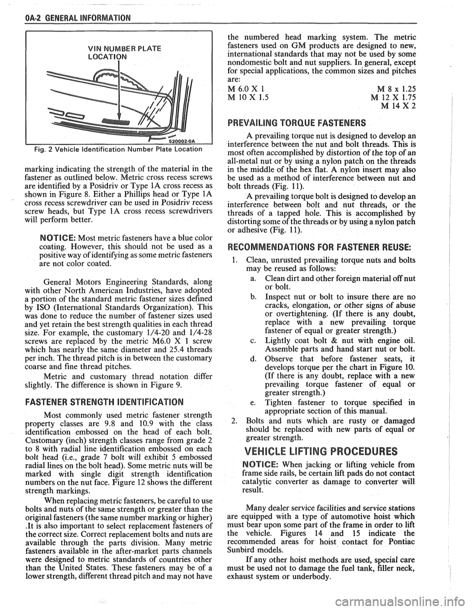
Fig. 2 Vehicle Identification Number Plate Location
marking indicating the strength of the material in the
fastener as outlined below. Metric cross recess screws
are identified by a Posidriv or Type
1A cross recess as
shown in Figure 8. Either a Phillips head or Type
1A
cross recess screwdriver can be used in Posidriv recess
screw heads, but Type
1A cross recess screwdrivers
will perform better.
NOTICE: Most metric fasteners have a blue color
coating. However, this should not be used as a
positive way of identifying as some metric fasteners
are not color coated.
General Motors Engineering Standards, along
with other North American Industries, have adopted
a portion of the standard metric fastener sizes defined
by
IS0 (International Standards Organization). This
was done to reduce the number of fastener sizes used
and yet retain the best strength qualities in each thread
size. For example, the customary 1/4-20 and 1/4-28
screws are replaced by the metric
M6.0 X 1 screw
which has nearly the same diameter and
25.4 threads
per inch. The thread pitch is in between the customary
coarse and fine thread pitches.
Metric and customary thread notation differ
slightly. The difference is shown in Figure 9.
FASTENER STRENGTH ODENTIFIGATION
Most commonly used metric fastener strength
property classes are 9.8 and 10.9 with the class
identification embossed on the head of each bolt.
Customary (inch) strength classes range from grade 2
to 8 with radial line identification embossed on each
bolt head
(i.e., grade 7 bolt will exhibit 5 embossed
radial lines on the bolt head). Some metric nuts will be
marked with single digit strength identification
numbers on the nut face. Figure 12 shows the different
strength markings.
When replacing metric fasteners, be careful to use
bolts and nuts of the same strength or greater than the
original fasteners (the same number marking or higher)
.It is also important to select replacement fasteners of
the correct size. Correct replacement bolts and nuts are
available through the parts division. Many metric
fasteners available in the after-market parts channels
were designed to metric standards of countries other
than the United States. These fasteners may be of a
lower strength, different thread pitch and may not have the
numbered head marking system. The metric
fasteners used on GM products are designed to new,
international standards that may not be used by some
nondomestic bolt and nut suppliers. In general, except
for special applications, the common sizes and pitches
are:
M 6.0
X 1
M 8 x 1.25
M 10 X 1.5 M 12 X 1.75
M 14x2 I
PREVAILING TORQUE FASTENERS
A prevailing torque nut is designed to develop an
interference between the nut and bolt threads. This is
most often accomplished by distortion of the top of an
all-metal nut or by using a nylon patch on the threads
in the middle of the hex flat.
A nylon insert may also
be used as a method of interference between nut and
bolt threads (Fig. 11).
A prevailing torque bolt is designed to develop an
interference between bolt and nut threads, or the
threads of a tapped hole. This is accomplished by
distorting some of the threads or by using a nylon patch
or adhesive (Fig. 11).
RECOMMENDATIONS FOR FASTENER REUSE: I
Clean, unrusted prevailing torque nuts and bolts
may be reused as follows:
a. Clean dirt and other foreign material off nut
or bolt.
b. Inspect nut or bolt to insure there are no
cracks, elongation, or other signs of abuse
or overtightening. (If there is any doubt,
replace with a new prevailing torque
fastener of equal or greater strength.)
c. Lightly coat bolt
& nut with engine oil.
Assemble parts and hand start nut or bolt.
d. Observe that before fastener seats, it
develops torque per the chart in Figure
10.
(If there is any doubt, replace with a new
prevailing torque fastener of equal or
greater strength.)
e. Tighten fastener to torque specified in
appropriate section of this manual.
Bolts and nuts which are rusty or damaged
should be replaced with new parts of equal or
greater strength.
VEHICLE LIF"TING PROCEDURES
NOTICE: When jacking or lifting vehicle from
frame side rails, be certain lift pads do not contact
catalytic converter as damage to converter will
result.
Many dealer service facilities and service stations
are equipped with a type of automotive hoist which
must bear upon some part of the frame in order to lift
the vehicle. Figures 14 and 15 indicate the
recommended areas for hoist contact for Pontiac
Sunbird models.
If any other hoist methods are used, special care
must be used not to damage the fuel tank, filler neck,
I
exhaust system or underbody. I
Page 56 of 1825
-
AIR CONDlTlQNlNG 1B-'13
METAL TUBE
THREAD AND
FITTING SIZE
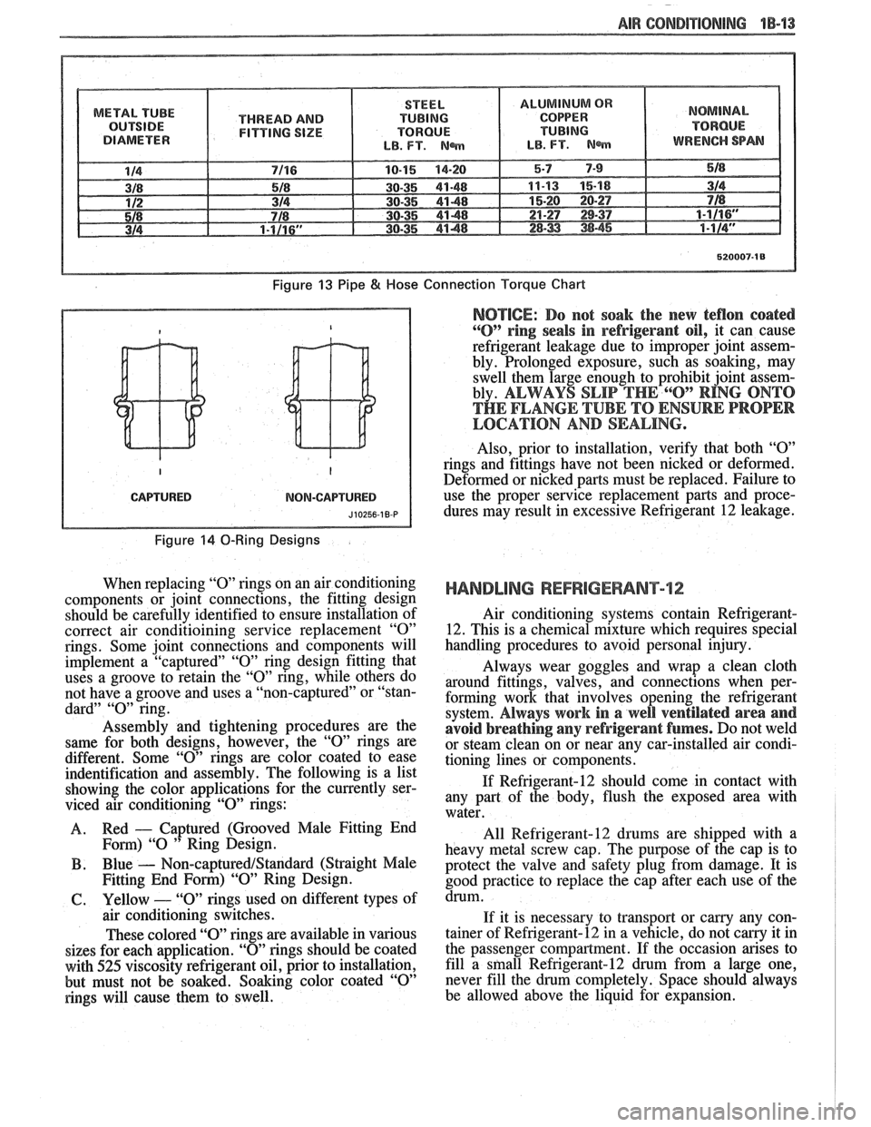
Figure 13 Pipe 8( Hose
CAPTURED NOM-CAPTURED
Figure 14 0-Ring Designs
When replacing "0" rings on an air conditioning
components or joint connections, the fitting design
should be carefully identified to ensure installation of
correct air conditioining service replacement
"0"
rings. Some joint connections and components will
implement a "captured"
"0" ring design fitting that
uses a groove to retain the
"0" ring, while others do
not have a groove and uses a "non-captured" or "stan-
dard"
"0" ring.
Assembly and tightening procedures are the
same for both designs, however, the
"0" rings are
different. Some
"0" rings are color coated to ease
indentification and assembly. The following is a list
showing the color applications for the currently ser-
viced air conditioning
"0" rings:
A. Red
- Captured
(Grooved Male Fitting End
Fom) "0 " Ring Design.
B . Blue - Non-captured/Standard (Straight Male
Fitting End
Form) "09' Ring Design.
61. Yellow - "0" rings used on different types of
air conditioning switches.
These colored "O" rings are available in various
sizes for each application.
"0" rings should be coated
with
525 viscosity refrigerant oil, prior to installation,
but must not be soaked. Soaking color coated
"0"
rings will cause them to swell.
Connection Torque Chart
NOTICE: Do not soak the new teflon coated
"0" ring seals in refrigerant oil, it can cause
refrigerant leakage due to improper joint assem-
bly. Prolonged exposure, such as soaking, may
swell them large enough to prohibit joint assem-
bly.
ALWAYS SLIP THE 6"O" RING ONTO
THE FLANGE TUBE TO ENSURE PROPER
LOCATION AND SEALING.
Also, prior to installation, verify that both "09'
rings and fittings have not been nicked or deformed.
Deformed or nicked
parts must be replaced. Failure to
use the proper service replacement parts and proce- dures may result in excessive Refrigerant
12 leakage.
HANDLING REFRIGERANT12
Air conditioning systems contain Refrigerant-
12. This is a chemical mixture which requires special
handling procedures to avoid personal injury.
Always wear goggles and wrap a clean cloth
around fittings, valves, and connections when per-
forming work that involves opening the refrigerant
system.
Always work in a well ventilated area and
avoid breathing
any refrigerant fumes. Do not weld
or steam clean on or near any car-installed air condi-
tioning lines or components.
If Refrigerant-12 should come in contact with
any part of the body, flush the exposed area with
water.
All
Refrigerant-12 drums are shipped with a
heavy metal screw cap. The purpose of the cap is to
protect the valve and safety plug from damage. It is
good practice to replace the cap after each use of the
drum.
If it is necessary to transport or carny any con-
tainer of Refrigerant-12 in a vehicle, do not
carry it in
the passenger compartment. If the occasion arises to
fill a
sfnall Refrigerant-12 drum from a large one,
never fill the drum completely. Space should always
be allowed above the liquid for expansion.
Page 66 of 1825
AIR CONDITIONING "18-23
10. CONTROL
14. LOWER MODE
DIAPHRAGM
16. DEFROST DIAPHRAGM
17. UPPER MODE
DIAPHRAGM
18. RECIRCULATION
5. TO WATER VALVE 19. lfVPUT (VIOLET)
6. A/C ELECTRICAL 20. DEFROST (BLUE)
21. LOWER MODE (TAN)
22. UPPER MODE (RED)
8. RECIRCULATION
DIAPHRAGM J~OZ~~-IB-F
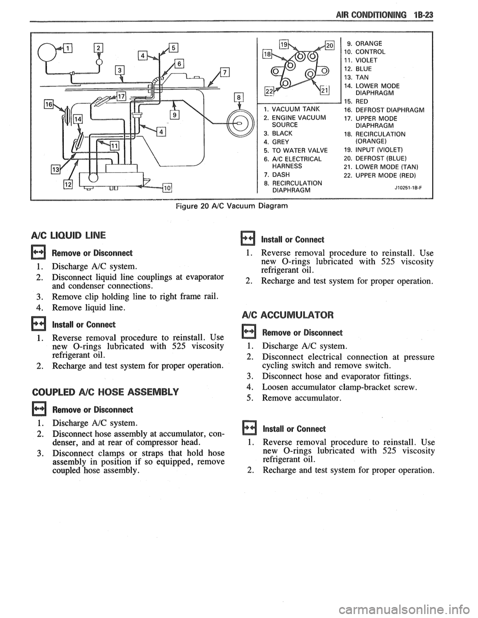
Figure 20 AIC Vacuum Diagram
NG LlCbUlB LINE
Remove or Disconnect
1. Discharge A!C system.
2. Disconnect liquid line couplings at evaporator
and condenser connections.
3. Remove clip holding line to right frame rail.
4. Remove liquid line.
lnstall or Conne&
1. Reverse removal procedure to reinstall. Use
new O-rings lubricated with
525 viscosity
refrigerant oil.
2. Recharge and test system for proper operation.
COUPLED NC HOSE ASSEMBLY
Remove or Disconne&
lnstall or Conne&
1. Reverse removal procedure to reinstall. Use
new O-rings lubricated with
525 viscosity
refrigerant oil.
2. Recharge and test system for proper operation.
Remove or Disconnect
1. Discharge A!C system.
2. Disconnect electrical connection at pressure
cycling switch and remove switch.
3. Disconnect hose and evaporator fittings.
4. Loosen accumulator clamp-bracket screw.
5. Remove accumulator.
1. Discharge
NC system.
2. Disconnect hose assembly at accumulator, con- Install or Connect
denser, and at rear of c6mpressor head. 1. Reverse removal procedure to reinstall. Use
3. Disconnect clamps or straps that hold hose new
O-rings lubricated with 525 viscosity
assembly in position if so equipped, remove refrigerant
oil.
coupled hose assembly.
2. Recharge and test system for proper operation.
Page 108 of 1825
CHASSIS SHEET METAL 2C-1
SECTION %C
CHASS S SHEET METAL
NOTICE: These fasteners are important attaching parts in that they could affect the performance of vital
parts and systems,
andlor could result in major repair expense. They must be replaced with one of the same part
number or with an equivalent part if replacement becomes necessary. Do not use a replacement part of lesser
quality or substitute design. Torque values must be used as specified during reassembly to assure proper retention
of all parts. There is to be no welding as it may result in extensive damage and weakening of the metal.
For prevailing torque
nut(s) and bolt(s), refer to the "Reuse of Prevailing Torque Nut(s) and Bolt(s)" chart in
Section OA.
CONTENTS
............................... General Description 2C-1
.............................................. Fasteners 2C- I
.......................... Anti-Corrosion Materials 2C- 1
................................ Service Procedures 2C-1
..................................... Hood Assembly 2C-1
.......................................... Hood Hinge 2C-2
........................................... Hood Latch 2C-2
......................................... Fender Panel 2C-3
.............................. Molding Replacement 2C-3
Aluminum Panel Repair Procedures
............. 2C-3
PaintingIRepairing Non-Metal Parts ............. 2C-3
RepairingIRefinishing Urethane
Bumpers and Front End Panels
................. 2C-4
.............................. Paint Color Matching 2C-5
Proper Identification and Painting of
............................. Interior Plastic Trim.. 2C-6
....................................... Test Procedure 2C-6
Painting Interior Plastic Parts
..................... 2C-6
...................... Polypropylene Plastic Parts .2C-6
Rigid or Hard Plastic Parts ....................... 2C-7
Vinyl and Flexible ABS Parts
.................... 2C-7
On-Vehicle Sewice ................................ 2C-7
GENERAL DESCRIPTION
FASTENERS SERVICE PROCEDURES
Many aluminum components are used in the
current models. Aluminum in contact with steel may
corrode rapidly if not protected by means of special
finishes or isolators.
Many of the fasteners used in the front sheet
metal area have the new GM
6174M finish which will
provide adequate protection. In some places, how-
ever, special fasteners are used in conjunction with
aluminum components. These special fasteners are
argent silver in order to more easily identify them
from the standard metric fasteners which are a
medium blue in color.
When replacing fasteners in the front sheet
metal area, it is advisable to avoid substitution of
otherwise similar fasteners in locations which should
use GM
6174M type fasteners or special fasteners for
aluminum components.
NOTICE: Failure to follow this precaution may
result in premature corrosion of the sheet metal in
the areas mentioned above.
ANTI-CORROSION MATERIALS
Anti-corrosion materials have been applied to
the interior surfaces of some metal panels to provide
rust resistance. When servicing these panels, areas on
which these materials have been disturbed should be
properly
recoated with service-type anti-corrosion
material.
HOOD ASSEMBLY
The hood is composed of a single outer panel
and an inner panel reinforcement. The hood may be
either steel or aluminum.
Adjust
Figure 1
Slotted holes are provided at all hood hinge
attaching points for proper adjustment
- both verti-
cally and fore and aft. Vertical adjustment at the front
may be made by adjusting rubber bumpers up and
down. For best appearance, make one adjustment at a
time.
TO RAISE OR LOWER THE REAR comers of
the hood for proper alignment to the fenders, and to
insure contact with the hood side wedges, proceed as
follows:
1. Loosen hinge-to-hood attaching screws.
2. Reposition hood assembly.
3. Tighten hinge-to-hood attaching screws to
specifications.
4. If necessary, repeat procedure on opposite side
of hood.
Page 113 of 1825
866 CHASSIS SHEET METAL
PROPER IDENTIFICATION AND CDAlrUmNG
OF INTERIOR PWSTIC TRlM
Interior plastic trim parts are normally supplied
in only one color. It is necessary to paint most parts.
Most vinyl headlinings and soft vinyl seat cushion and
hack cover assemblies are furnished in colors.
Instructions on how to identify each paintable
plastic part, and how to apply the available paint
materials are as follows:
Paintable plastic trim components, as used on
General Motors interiors, can be divided into three
general types:
@ Polypropylene Plastic
@ ABS Plastic
@ Vinyl Plastic
Excluding the soft vinyl seat cushion and seat
back trim cover assemblies, the plastic used most
widely on the interior of bodies is "POLYPROPYL-
ENE" and, as noted later, requires special refinishing
materials and procedures. Therefore, it is important
for a painter to be able to identify each plastic in order
to paint it satisfactorily. The purpose of the following
tests is to determine the identity of a given plastic so
that the proper paint procedure and refinishing mate-
rials will be used.
TEST PROCEDURE
Polypropylene, ABS or Vinyl Plastic
From a hidden backside portion of the part,
remove a sliver of plastic with a sharp blade.
Holding the sliver with needle-nose pliers, put it
to a flame and observe whether or not any
smoke is given off when burning.
ABS PLASTIC will give off a HEAVY BLACK
SMOKE, and POLYPROPYLENE will burn
clean.
However, if a sliver gives off OTHER THAN
HEAVY BLACK SMOKE, it is either DIRTY
POLYPROPYLENE OR IS VINYL. To deter-
mine which it is, the following burn test should
be made with the hot tip of a clean copper wire.
Heat the tip of the copper wire to a "red-glow"
with a propane (gas) torch.
Touch the heated wire to a hidden portion of the
plastic in question, to get some of the plastic on
the wire.
Return the wire, with its
now plastic-coated tip,
to the flame and observe for flame color.
If the flame given off from the wire is of the
GREEN-TURQUOISE-BLUE RANGE, then
the PLASTIC IS VINYL. (Any other color
flame would indicate the material is dirty poly-
propylene.
)
PAINWING lNTERiOR PWSTIC PARTS
Before painting, always check the body number
plate of the car for the
correct trim code color number
for that model year. The body number plate is located
on the upper horizontal surface of the shroud. Interior
color is color keyed to this "Trim Combination Num-
ber" (TR) on the body plate. Each paint supplier pro-
vides an interior color chart which identifies their
stock number, color name, gloss factor and trim com-
bination number for each "conventional" interior
color. Charts listing "vinyl" interior colors are also
provided.
"CONVENTIONAL" interior acrylic colors are
designed for use only on hard trim parts, such as:
1. Steel parts (primer or sealer required on new
service parts).
2. Hard POLYPROPYLENE plastic ("Special
Primer" required
- See GM Parts Catalog).
3. Hard ABS plastic (NO primer necessary).
"VINYL" interior colors are designed for soft
and/or flexible trim parts, such as instrument panel
cover pad assemblies, upper door trim pad assem-
blies, molded headlining panels, head rests and assist
handles. These colors require a final top coat of clear
vinyl spray, with instrument panel pads requiring a
"nonglare" clear final top coat. Other trim parts
require a degree of gloss to match similar adjacent
parts.
POLYPROPYLENE PUSTIC PARTS
The system for painting polypropylene parts
involves the use of a special primer. It is essential that
the service part be first primed with a coating of spe-
cial POLYPROPYLENE PRIMER (Detroit
Autobody
#PP-2250, or equivalent) according to factory recom-
mendations on the can. Because the primer acts as a
bonding agent between the plastic and acrylic lacquer, failure to use it will result in color coat "lifting"
and/or
"peeling" problems. After priming, the part can be
color coated with conventional interior acrylic
lacquer,
PROCEDURE
1. Wash part thoroughly with a cleaning solvent ("Acryli-Clean," "Prep-Sol," or equivalent) that
will not leave any greasy film.
2. Apply a thin, wet coat of the special polypropyl-
ene primer according to label directions on can.
Wetness of primer is best determined by observ-
ing gloss reflection of spray application in ade-
quate lighting. Be sure primer application
includes all edges. Allow
the primer to flash dry
ONE (1) MINUTE MINIMUM and TEN (10)
MINUTES MAXIMUM. (If the flash period
before color coating should extend beyond ten
minutes, the primer MUST be reapplied to
avoid previously mentioned adhesion
problems
.)
Page 145 of 1825
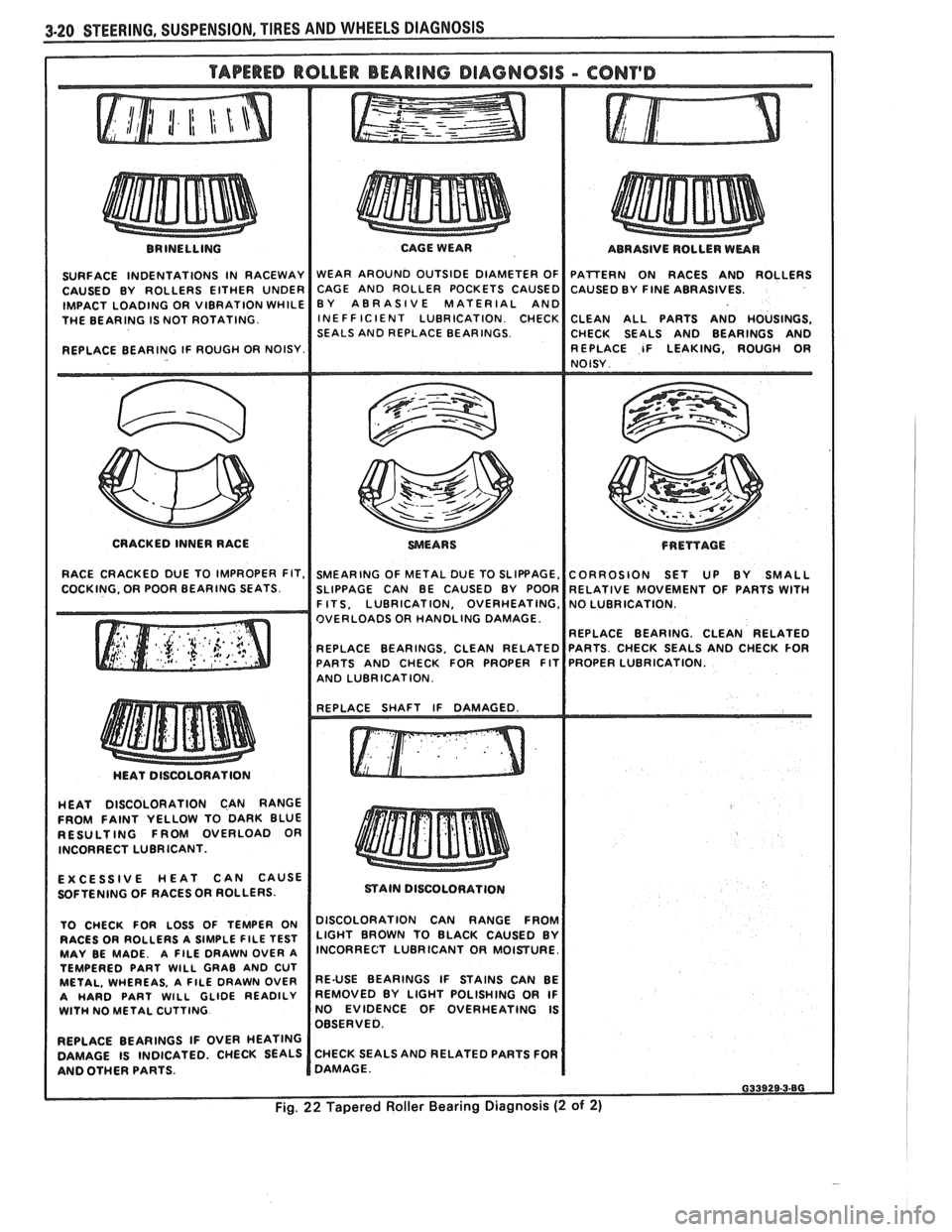
BRINELLING
SURFACE INDENTATIONS IN RACEWAY
CAUSED BY ROLLERS EITHER UNDER
IMPACT LOADING OR VIBRATION WHILE
THE BEARING IS NOT ROTATING.
REPLACE BEARING IF ROUGH OR NOISY. CAGE WEAR
WEAR AROUND OUTSIDE DIAMETER OF
CAGE AND ROLLER POCKETS CAUSED
BY ABRASIVE MATERIAL AND
INE FF IClENT LUBRICATION CHECK
SEALS AND REPLACE BEARINGS. ABRASIVE
ROLLER WEAR
PATTERN ON RACES AND ROLLERS
CAUSED BY
FINE ABRASIVES.
CLEAN ALL PARTS AND HOUSINGS,
CHECK SEALS AND BEARINGS AND
REPLACE IF LEAKING, ROUGH
OR NOISY
CRACKED INNER RACE
WEARS FRETfAGE
RACE CRACKED DUE TO IMPROPER FIT, SMEARING OF METAL DUE TO SLIPBAGE, CORROSION SET UP BY SMALL
COCKING. OR POOR BEARING SEATS. SLIPPAGE CAN BE CAUSED BY POOR RELATIVE MOVEMENT OF PARTS WITH I F ITS. LUBRICATION, OVERHEATING,
OVERLOADS OR HANDLING DAMAGE
REPLACE BEARING. CLEAN RELATED
REPLACE BEARINGS, CLEAN RELATED
PARTS AND CHECK FOR PROPER FIT
I AND LUBRICATION. I I
HEAT DISCOLORATION CAN RANGE
FROM FAINT YELLOW TO DARK BLUE
RESULTING FROM OVERLOAD OR
INCORRECT LUBRICANT.
EXCESSIVE HEAT CAN CAUSE
SOFTENING OF RACES
OR ROLLERS.
TO CHECK FOR LOSS OF TEMPER ON
RACES OR ROLLERS A SIMPLE
FlLE TEST MAY BE MADE. A FILE DRAWN OVER A
TEMPERED PART WlLL GRAB AND CUT
METAL. WHEREAS, A FlLE DRAWN OVER
A HARD PART WlLL GLIDE READILY WlTH NO METAL CUTTING
REPLACE BEARINGS IF OVER HEATING
DAMAGE IS INDICATED. CHECK SEALS
AND OTHER PARTS.
mAIN DISCOLORATION
I DISCOLORATION CAN RANGE FROM
LIGHT BROWN TO BLACK CAUSED BY
INCORRECT LUBRICANT OR MOISTURE.
RE-USE BEARINGS IF STAINS CAN BE
REMOVED BY LIGHT POLISHING OR IF
NO EVIDENCE OF OVERHEATING IS
OBSERVED.
CHECK SEALS AND RELATED PARTS FOR
DAMAGE.
Page 259 of 1825
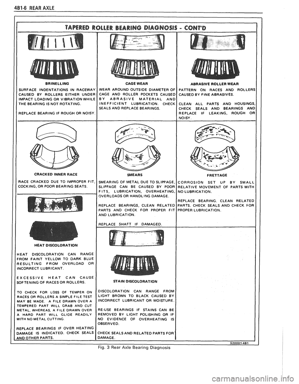
4B1-6 REAR AXLE
THE BEARING IS NOT ROTATING.
SEALS AND REPLACE BEARINGS. CHECK SEALS AND BEARINGS AND
CRACKED INNER RACE
F R ETTAGE
OVERLOADS OR HANDLING DAMAGE.
AND LUBRICATION.
HEAT DISCOLORATION CAN RANGE
FROM FAINT YELLOW TO DARK BLUE
RESULTING FROM OVERLOAD OR
INCORRECT LUBRICANT.
EXCESSIVE HEAT CAN CAUSE
SOFTENING OF RACES OR ROLLERS.
STAIN DISCOLORATION
TEMPERED PART
WILL GRAB AND CUT
WITH NO METAL CUTTING. NO EVIDENCE OF OVERHEATING IS
Fig. 3 Rear Axle Bearing Diagnosis
Page 278 of 1825
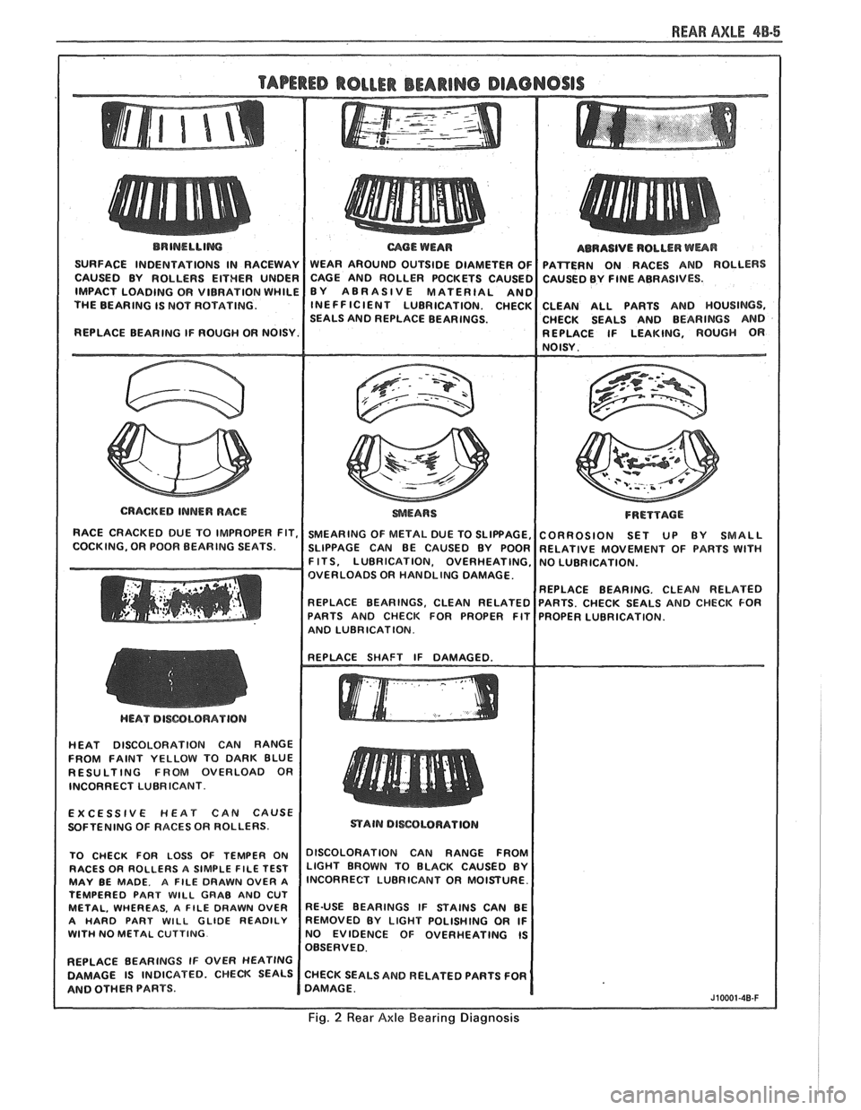
REAR AXLE 48-5
BRINELLIM
SURFACE INDENTATIONS IN RACEWAY
CAUSED BY ROLLERS EITHER UNDER
IMPACT LOADING OR VIBRATION WHILE
THE BEARING IS NOT ROTATING.
REPLACE BEARING IF ROUGH OR NOISY.
I
CRACKED INNER RACE
RACE CRACKED DUE TO IMPROPER FIT,
COCKING, OR POOR BEARING SEATS.
mOE WEAR
WEAR AROUND OUTSIDE DIAMETER OF
CAGE AND ROLLER POCKETS CAUSEC
BY ABRASIVE MATERIAL
AN0 INEFFICIENT LUBRICATION. CHECK
SEALS AND REPLACE BEARINGS.
SMEARING OF METAL DUE TO SLIPPAGE,
SLIPPAGE CAN BE CAUSED BY POOR
F ITS, LUBRICATION, OVERHEATING,
OVERLOADS OR HANDLING DAMAGE.
REPLACE BEARINGS. CLEAN RELATED
PARTS AND CHECK FOR PROPER FIT
AND LUBRICATION. ABRASIVE
ROLLER
WUR
PAmERN ON RACES AND ROLLERS
CAUSED BY FINE ABRASIVES.
CLEAN ALL PARTS AND HOUSINGS,
CHECK SEALS AND BEARINGS AND
REPLACE IF LEAKING, ROUGH
OR NOISY.
FRETTACE
CORROSION SET UP BY SMALL
RELATIVE MOVEMENT OF PARTS WlTH
NO LUBRICATION.
REPLACE BEARING. CLEAN RELATED
PARTS. CHECK SEALS AND CHECK FOR
PROPER LUBRICATION.
HEAT DISCOLORATION CAN RANGE
FROM FAINT YELLOW TO DARK BLUE
RESULTING FROM OVERLOAD OR
INCORRECT LUBRICANT.
EXCESSIVE
HEAT CAN CAUSE
SOFTENING OF RACES OR ROLLERS.
TO CHECK FOR LOSS OF TEMPER ON
DISCOLORATION CAN RANGE FFmM RACES OR ROLLERS A SIMPLE FILE TEST LIGHT BROWN TO BLACK CAUSED BY MAY BE MADE. A FILE DRAWN OVER A lNCORRECT LUBRICANT OR MOISTURE.
TEMPERED PART
WlLL GRAB AND CUT METAL, WHEREAS. A FILE DRAWN OVER RE-USE BEARINGS IF STAINS CAN BE
A HARD PART WILL GLIDE READILY REMOVED BY LIGHT POLISHING OR IF WITH NO METAL CUTTING NO EVIDENCE OF OVERHEATING IS
OBSERVED.
REPLACE BEARINGS IF OVER
HEATING
DAMAGE IS INDICATED. CHECK SEALS CHECK SEALS AND RELATED PARTS FOR
AND OTHER PARTS. DAMAGE.
J10001-40-F
Fig. 2 Rear Axle Bearing Diagnosis
Page 423 of 1825
88-12 ENGINE COOLING
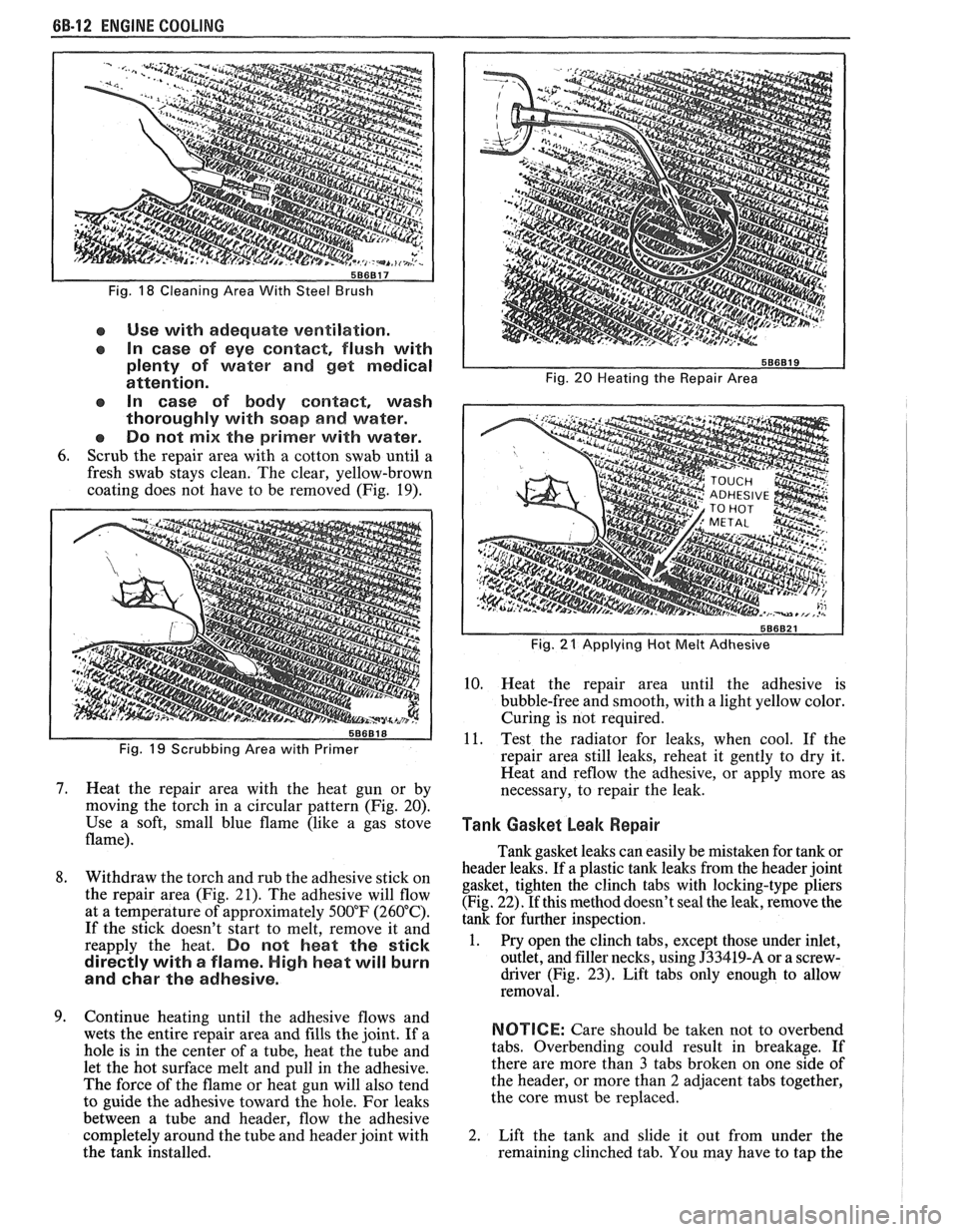
Fig. 18 Cleaning Area With Steel Brush
e Use with adequate ventilation.
In case of eye contact, flush with
plenty of water and get medical
attention.
In case of body
contact, wash
thoroughly with soap
and water.
Do not
mix the primer with water.
6. Scrub the repair area with a cotton swab until a
fresh swab stays clean. The clear, yellow-brown
coating does not have to be removed (Fig. 19).
Fig. 19 Scrubbing Area with Primer
7. Heat the repair area with the heat gun or by
moving the torch in a circular pattern (Fig. 20).
Use a soft, small blue flame (like a gas stove
flame).
8. Withdraw the torch and rub the adhesive stick on
the repair area (Fig. 21). The adhesive will flow
at a temperature of approximately 500°F (260°C).
If the stick doesn't start to melt, remove it and
reapply the heat.
Do not heat the stick
directly with
a flame. High heat will burn
and
char the adhesive.
9. Continue heating until the adhesive flows and
wets the entire repair area and fills the joint. If a
hole is in the center of a tube, heat the tube and
let the hot surface melt and pull in the adhesive.
The force of the flame or heat gun will also tend
to guide the adhesive toward the hole. For leaks
between a tube and header, flow the adhesive
completely around the tube and header joint with
the tank installed.
Fig. 20 Heating the Repair Area
I
Fig. 21 Applying Hot Melt Adhesive I
10. Heat the repair area until the adhesive is
bubble-free and smooth, with a light yellow color.
Curing is not required.
11. Test the radiator for leaks, when cool. If the
repair area still leaks, reheat it gently to dry it.
Heat and
reflow the adhesive, or apply more as
necessary, to repair the leak.
Tank Gasket beak Repair I 1
Tank gasket leaks can easily be mistaken for tank or
header leaks. If a plastic tank leaks from the header joint
gasket, tighten the clinch tabs with locking-type pliers
(Fig. 22). If this method doesn't seal the leak, remove the
tank for further inspection.
1. Pry open the clinch tabs, except those under inlet,
outlet, and filler necks, using
J33419-A or a screw-
driver (Fig.
23). Lift tabs only enough to allow
removal.
NOTICE: Care should be taken not to overbend
tabs. Overbending could result in breakage. If
there are more than
3 tabs broken on one side of
the header, or more than
2 adjacent tabs together,
the core must be replaced.
2. Lift the tank and slide it out from under the
remaining clinched tab. You may have to tap the
Page 472 of 1825
IGNITION SYSTEM 6B4-3
flash-over, which causes engine misfiring. Do not
mistake corona discharge for flash-over, or a shorted
insulator. Corona is a steady blue light appearing
around the insulator, just above the shell crimp. It is
the visible evidence of a high-tension field and has no
effect on ignition performance. Usually it can be
detected only in darkness. This discharge may repel
dust particles, leaving a clear ring on the insulator just
above the shell. This ring is sometimes mistakenly
regarded as evidence that combustion gases have blown
out between shell and insulator.
lgnition Switch
The mechanical switch is located in the steering
column on the right hand side just below the steering
wheel. The electrical switching portion of the assembly
is separate from the key and lock cylinder. However,
both are synchronized and work in conjunction with
each other through the action of the actuator rod
assembly.
For a complete explanation of the key and lock
cylinder, and the actuator rod assembly, see
STEERING, Section
38. See Section 8 for electrical
switching.
DIAGNOSIS
IGNITION SYSTEM
Spark Plugs
Worn or dirty plugs may give satisfactory
operation at idling speed, but at higher RPM they
frequently fail. Faulty plugs are indicated in a number
of ways: poor fuel economy, power loss, loss of speed,
hard starting and generally poor engine performance.
Spark plugs may also fail due to carbon fouling,
excessive gap, or a broken insulator. Fouled plugs may
be indicated by black carbon
deposits. The black deposits are usually the result of
slow-speed driving and short runs, where sufficient
engine operating temperature is seldom reached. Worn
pistons, rings, faulty ignition, over-rich carburetion
and spark plugs which are too cold will also result in
carbon deposits.
Excessive gap wear, on plugs of low mileage,
usually indicates the engine is operating at high speeds,
or loads that are consistently greater than normal, or
that a plug which is too hot is being used. Electrode
wear may also be the result of plug overheating,
causcd
by combustion gases leaking past the threads due to
insufficient torquing of the spark plug. Excessively lean
carburetion will also result in accelerated electrode
wear.
Broken insulators are usually the result of
improper installation, or carelessness when regapping
the plug. Broken upper insulators usually result from
a poor fitting wrench, or an outside blow. The cracked
insulator may not show up right away, but will as soon
as oil or moisture penetrates the crack. The crack is
usually just below the crimped part of shell and may
not be visible.
Broken lower insulators usually result from
carelessness when regapping and generally are visible.
This type of break may result from the plug operating
too "hot", which may happen in periods of high-speed
operation or under heavy loads. When regapping a
spark plug, always make the gap adjustment by
bending the ground (side) electrode. Spark plugs with
broken insulators should always be replaced.
HE1 Distributor
See Unit Repair for distributor disassembly, test
and reassembly of individual distributor components,
when the distributor is removed from the vehicle. See
On-Car Service for distributor removal and installation
and for component removal with distributor in car. See
Section 6E for
HE1 and EST diagnosis.
SERVICE PROCEDURES
IGNITION SYSTEM
Distributor Ignition
NOTICE: This procedure is generally true for
most carlines. Where procedure is different, or
where additional information is required, see
"ON-CAR SERVICE" for specific
carline.
HE1 DISTRIBUTOR
Service Precautions
1. When making compression checks, disconnect
the ignition switch feed wire at the distributor.
When disconnecting this connector,
do not use
a screwdriver or tool to release the locking tab, as
it may break.
2. No periodic lubrication is required. Engine oil
lubricates the lower bushing and an oil-filled
reservoir provides lubrication for the upper
bushing. 3.
The tachometer (TACH) terminal is next to the
ignition switch (BAT) connector on the
distributor cap.
NOTICE: The tachometer terminal must
NEVER be allowed to touch ground, as damage
to the module and/or ignition coil can result.
Some tachometers currently in use may NOT be
compatible with the High Energy Ignition System.
Consult the manufacturer of the tachometer if
questions arise.
4. Dwell adjustment is controlled by the module,
and cannot be adjusted.
5. The material used to construct the spark plug
cables is very soft. This cable will withstand more
heat and carry a higher voltage, but scuffing and
cutting become easier. The spark plug cables
must be routed correctly to prevent
chafing or
cutting. See Spark Plug Section. When removing