oil filter PONTIAC FIERO 1988 Service Repair Manual
[x] Cancel search | Manufacturer: PONTIAC, Model Year: 1988, Model line: FIERO, Model: PONTIAC FIERO 1988Pages: 1825, PDF Size: 99.44 MB
Page 8 of 1825
GENERAL INFORMATION OA-5
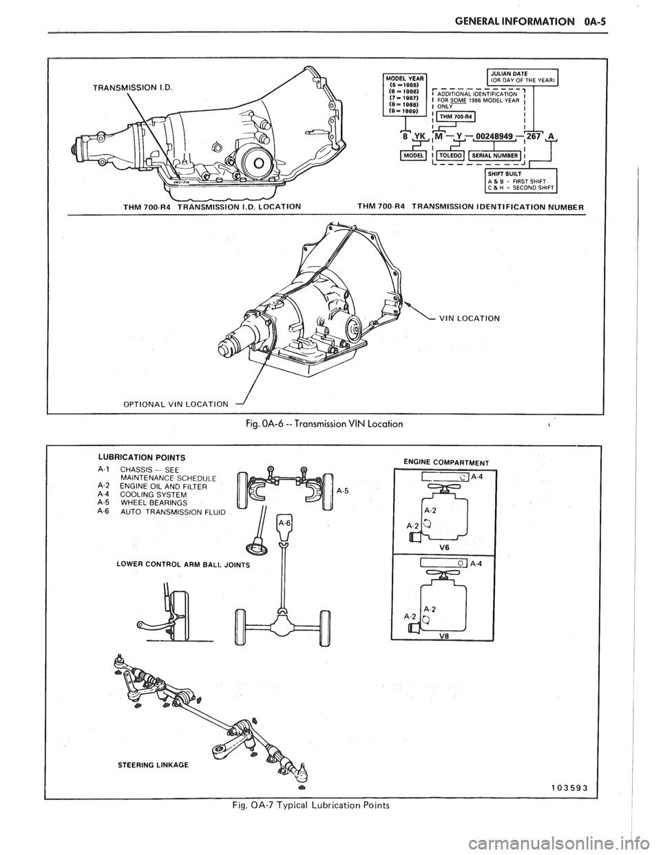
- THM 700-R4 TRANSMISSION I.D. LOCATION
1-1 IOU DAY OF THE YEAR1
I SHIFT BUILT 1 1 A & B = FIRST SHIFT 1 C 5 H - SECOND SHIFT
THM 700-R4 TRANSMISSION IDENTIFICATION NUMBER
VIN LOCATION
I OPTIONAL VIN LOCATION --I I
Fig. OA-6 --Transmission VIN Location
LUBRICATION POINTS
CHASSIS - SEE
MAINTENANCE SCHEDULE
ENGINE OIL AND FILTER
COOLING SYSTEM WHEEL BEARINGS
AUTO TRANSMISSION FLUID
LOWER CONTROL ARM BALL JOINTS
I I
ENGINE COMPARTMENT
STEERING LINKAGE
Fig. OA-7 Typical Lubrication Points
Page 10 of 1825
GENERAL INFORMATION OA-7
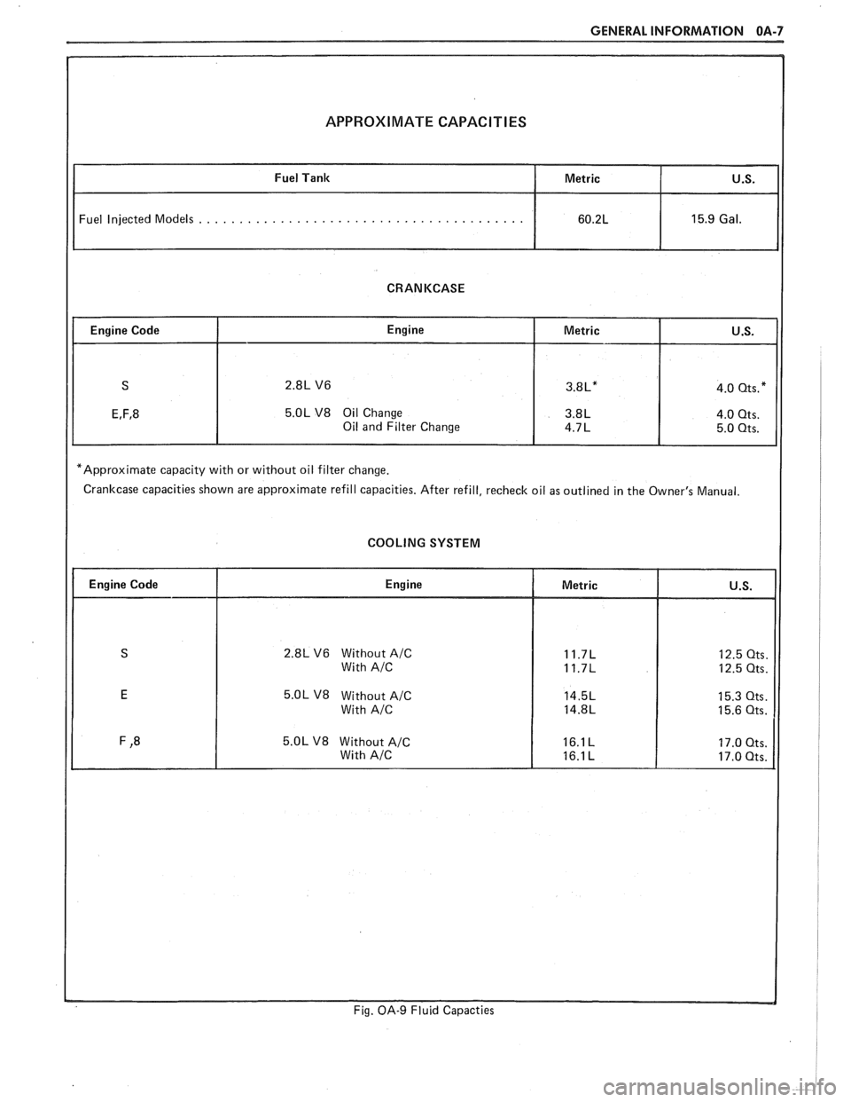
APPROXIMATE CAPACITIES
Fuel Injected Models . . . . . . . . . . . . . . . . . . . . . . . . . . . . . . . . . . . . . . . .
CRANKCASE
5.OL V8 Oil Change
*Approximate capacity with or without oil filter change.
Crankcase capacities shown are approximate refill capacities. After refill, recheck oil as outlined in the Owner's Manual.
COOLING SYSTEM
2.8L V6 Without A/C
5.OL V8 Without A/C
Fig. OA-9 Fluid Capacties
Page 18 of 1825
MAINTENANCE AND LUBRICATION OB-1
SECTION OB
NTENANCE AND LUBR
CONTENTS
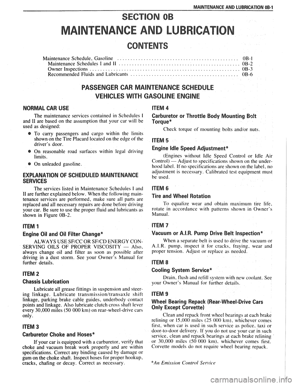
Maintenance Schedule, Gasoline .............................................. OB-l
Maintenance Schedules I and 11 .............................................. OB-2
Owner Inspections
......................................................... OB-3
Recommended Fluids and Lubricants ......................................... OB-6
PASSENGER CAR MAINTENANCE SCHEDULE
VEHICLES
WITH GASOLINE ENGINE
NORMAL CAR USE ITEM 4
The maintenance services contained in Schedules I Carburetor or Throttle Body Mounting Bolt
and 11 are based on the assumption that your car will be Torque* used as designed:
Check torque of mounting bolts and/or nuts. @ To carry passengers and cargo within the limits
shown on the Tire Placard located on the edge of the ITEM 5 driver's door.
@ On reasonable road surfaces within legal driving Engine Idle Speed Adjustment*
limits. (Engines
without Idle Speed Control or Idle Air
Control) - Adjust to specifications shown on the under- @ On unleaded gasoline.
hood label. If no specifications are shown on the label, no
adjustment is necessary. Calibrated test equipment must
EXPLANATION OF SCHEDULED MAINTENANCE be used. SERVICES
The services listed in Maintenance Scheduies I and ITEM 6
11 are further explained below. When the following main- ~i~~ and wheel aotation tenance services are performed, make sure all parts are
replaced and all necessary repairs are done before driving To equalize wear and obtain maximum tire life,
your car. Be sure to use the proper fluid and lubricants as rotate in accordance with patterns shown in Owner's
shown in Figure OB-2. Manual.
ITEM 1
Engine Oil and Oil Filter Change*
ALWAYS USE SFICC OR SF/CD ENERGY CON-
SERVING OILS OF PROPER VISCOSITY
- Also.
always change oil and filter as soon as possible after
driving in a dust storm. See your Owner's Manual for
further details.
ITEM 2
Chassis Lubrication
Lubricate all grease fittings in suspension and steer-
ing linkage. Lubricate
transmissionltransaxle shift
linkage, parking brake cable guides, underbody contact
points and linkage. Also lubricate clutch cross shaft lever
every
30,000 miles (50 000 km) on rear-wheel-drive cars
only.
ITEM 3
Carburetor Choke and Hoses*
If your car is equipped with a carburetor, verify that
choke and vacuum break work properly and are within
specifications. Correct any binding caused by damage or
gum on the choke shaft. Inspect hoses for proper hookup,
cracks, chafing or decay. Correct as necessary.
Vacuum or A.I.R. Pump Drive Belt Inspection*
When a separate belt is used to drive the vacuum or
A.I.R.
pump, inspect it for cracks, fraying, wear and
proper tension. Adjust or replace as needed.
ITEM 8
Cooling System Service*
Drain, flush and refill system with new coolant. See
your Owner's Manual
for further details.
ITEM 9
Wheel Bearing Repack (Rear-Wheel-Drive Cars
Only Except Corvette)
Clean and repack front wheel bearings at each brake
relining or 15,000 miles
(25 000 km), whichever comes
first, when car is used in such service as police, taxi or
door-to-door delivery. If you do not use your car in such
service, clean and repack bearings at each brake relining
or 30,000 miles
(50 000 km), whichever comes first.
Corvette models do not require wheel bearing repack.
Page 44 of 1825
AIR CONDITIONING 1B-1
SECTION 1B
R COND
When performing air conditioning diagnosis on vehicles equipped with a catalytic converter, it will be necessary to
WARM the engine to a NORMAL operating temperature BEFORE attempting to idle the engine for periods greater
than five
(5) minutes. Once the engine attains normal idle, diagnosis and adjustments can be made.
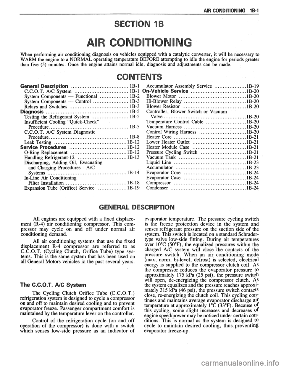
CONTENTS
.................. General Description .................................. 1B-1 Accumulator Assembly Service .1B-19
.......................... C.C.O.T. A!C System ................................ 1B-1 On-Vehicle Sewice ..... 1B-20
....................................... System Components - Functional ................. 1B-2 Blower Motor .1B-20
..................................... System Components - Control ..................... 1B-3 Hi-Blower Relay 1B-20
...................................... Relays and Switches ................................... 1B-3 Blower Resistor 1B-20
Diagnosis ................................................. 1B-5 Controller, Blower Switch or Vacuum
................................................ Testing the Refrigerant System ...................... 1B-5 Valve .lB-20
Insufficient Cooling "Quick-Check Temperature Control Cable ....................... .1B-20
.................................... Procedure.. ............................................. 1B-5 Vacuum
Harness .lB-20
C.C.O.T. A/C System Diagnostic Control Wiring Harness ........................... .1B-20
..... ................................. Procedure.. ............................................. 1B-8 Heater
Core .. .lB-21
................................ Leak Testing ........................................... 1B-12 Lower Heater Outlet 1B-21
............................... Service Procedures ................................. .1B-12 Heater Module Case .lB-21
.......................... O-Ring Replacement ................................ .1B- 12 Pressure Cycling Switch .1B-21
....................................... Handling Refrigerant- 12 ............................ .1B- 13 Vacuum Tank .lB-21
Discharging, Adding Oil, Evacuating Liquid Line .......................................... .1B-23
and
Charging Procedures - AIC Accumulator ......................................... .1B-23
.................................... Systems .............................................. .1B-14 Evaporator Core .1B-24
In-Line Air Conditioning Evaporator Case .................................... .1B-24
.......................................... Filter
Installation.. .................................. .1B- 18 Compressor .lB-24
.............................................
................ Expansion Tube (Orifice) Service .1 B- 19 Condenser IB-24
GENERAL DESCRIPTION
All engines are equipped with a fixed displace- evaporator temperature. The pressure cycling switch
ment (R-4) air conditioning compressor. This
com- is the freeze protection device in the system and
pressor may cycle on and off under normal air
senses refrigerant pressure on the suction side of the
conditioning demand. system. This switch is located on a standard
Schrader- -
All air conditioning systems that use the fixed
displacement R-4 compressor are referred to as
C. C.O.T. (Cycling Clutch, Orifice Tube) type sys-
tems. This is the same system that has been used on
all General Motors vehicles in the past several years.
The C.C.O.T. NG System
The Cycling Clutch Orifice Tube (C.C.O.T.)
refrigeration system is designed to cycle a compressor
on and off to maintain desired cooling and to prevent
evaporator freeze. Passenger compartment comfort is
maintained by the temperature lever on the controller.
Control of the refrigeration cycle (on and off
operation of the compressor) is done with a switch
which senses low-side pressure as an indicator of type
valve low-side fitting. During air temperatures
over 10°C
(50°F), the equalized pressures within the
charged
A/C system will close the contacts of the
pressure switch. When an air conditioning mode
(max, norm, bi-level, defrost) is selected, electrical
energy is supplied to the compressor clutch coil. AS
the compressor reduces the evaporator pressure
to
approximately 175 kPa (25 psi), the pressure switch
will open, de-energizing the compressor clutch.
As
the system equalizes and the pressure reaches approxl-
mately 315 kPa (46 psi), the pressure switch contacts
close, re-energizing the clutch coil. This cycling
coy
tinues and maintains average evaporator discharge air
temperature at approximately 1°C (33°F). Because of
this cycling, some slight increases and decreases of
engine speedlpower may be noticed under certain con-
ditions. This is normal as the system is designed
to
cycle to maintain desired cooling, thus preventing
evaporator freeze-up.
Page 45 of 1825
18-2 AIR CONDITIONING
SYSTEM GONIPONENE - FFUNCnIONAL
Compressor
All compressors are belt driven from the engine
crankshaft through the compressor clutch pulley. The
compressor pulley rotates without driving the com-
pressor shaft until an electromagnetic clutch coil is
energized. When voltage is applied to energize the
clutch coil, the clutch plate and hub assembly is
drawn rearward toward the pulley. The magnetic
force locks the clutch plate and pulley together as one
unit to drive the compressor shaft.
As the compressor shaft is driven, it compresses
the low-pressure refrigerant vapor from the evaporator
into a high-pressure, high-temperature vapor. Carried
with the refrigerant is the refrigerant oil which is used
to lubricate the compressor. Complete compressor
overhaul procedures can be found in Section
ID of the
General Service Manual.
Pressure Relief Valve
The compressor is equipped with a pressure
relief valve which is placed in the system as a safety
factor. Under certain conditions, the refrigerant on the
discharge side may exceed the designed operating
pressure. To prevent system damage, the valve is
designed to open automatically at approximately
3036
kPa (440 psi). Conditions that might cause this valve
to open (defective high pressure cut-off switch, inop-
erative electric cooling fan, etc.) should be corrected,
and the refrigerant oil and refrigerant should be
replaced as necessary.
A muffler is used on some refrigerant systems to
reduce compressor noises from high or low pressure
vibrations.
Condenser Gore
The condenser assembly in front of the radiator
is made up of coils which carry the refrigerant TO
cooling fins to provide rapid transfer of heat. The air
passing through the condenser cools the high-pressure
refrigerant vapor causing it to condense to a liquid.
Expansion (Orifice) Tube
The plastic expansion tube, with its mesh screen
and orifice, is located in the evaporator inlet pipe at
the liquid line connection. It provides a restriction to
the high-pressure liquid refrigerant in the liquid line,
metering the flow of refrigerant to the evaporator as a
low-pressure liquid. The expansion tube and orifice
are protected from contamination by filter screens on
both inlet and outlet sides. The tube is serviced only
as a replacement assembly.
When the engine is turned "OFF" with the
A/C
system operating, the refrigerant in the system will
flow from the high-pressure side of the expansion tube (orifice) to the low-pressure side until the pressure
is
equalized. This may be detected as a faint sound of
liquid flowing (hissing) for 30 to
60 seconds and is a
normal condition.
Evaporator Gore
The evaporator is a device which cools and
dehumidifies the air before it enters the car. High-
pressure liquid refrigerant flows through the expan-
sion tube (orifice) into the low-pressure area of the
evaporator. The heat in the air passing through the
evaporator core is transferred to the cooler surface of
the core, thereby cooling the air. As the process of
heat transfer from the air to the evaporator core sur-
face is taking place, any moisture (humidity) in the air
condenses on the outside surface of the evaporator
core and is drained off as water.
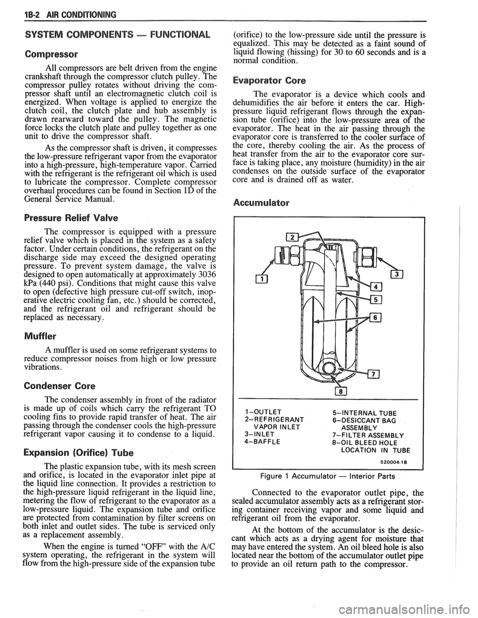
Accumulator
5-INTERNAL TUBE
2-REFRIGERANT 6-DESICCANT BAG
VAPOR INLET ASSEMBLY
7-FILTER ASSEMBLY
8-OIL BLEED HOLE
LOCATION IN TUBE
520004-1 8
Figure 1 Accumulator - Interior Parts
Connected to the evaporator outlet pipe, the
sealed accumulator assembly acts as a refrigerant stor-
ing container receiving vapor and some liquid and
refrigerant oil from the evaporator.
At the bottom of the accumulator is the desic-
cant which acts as a drying agent for moisture that
may have entered the system. An oil bleed hole is also
located near the bottom of the accumulator outlet pipe
to provide an oil return path to the compressor.
Page 61 of 1825
LlOQllD LiNE FILTER INSTALLATION
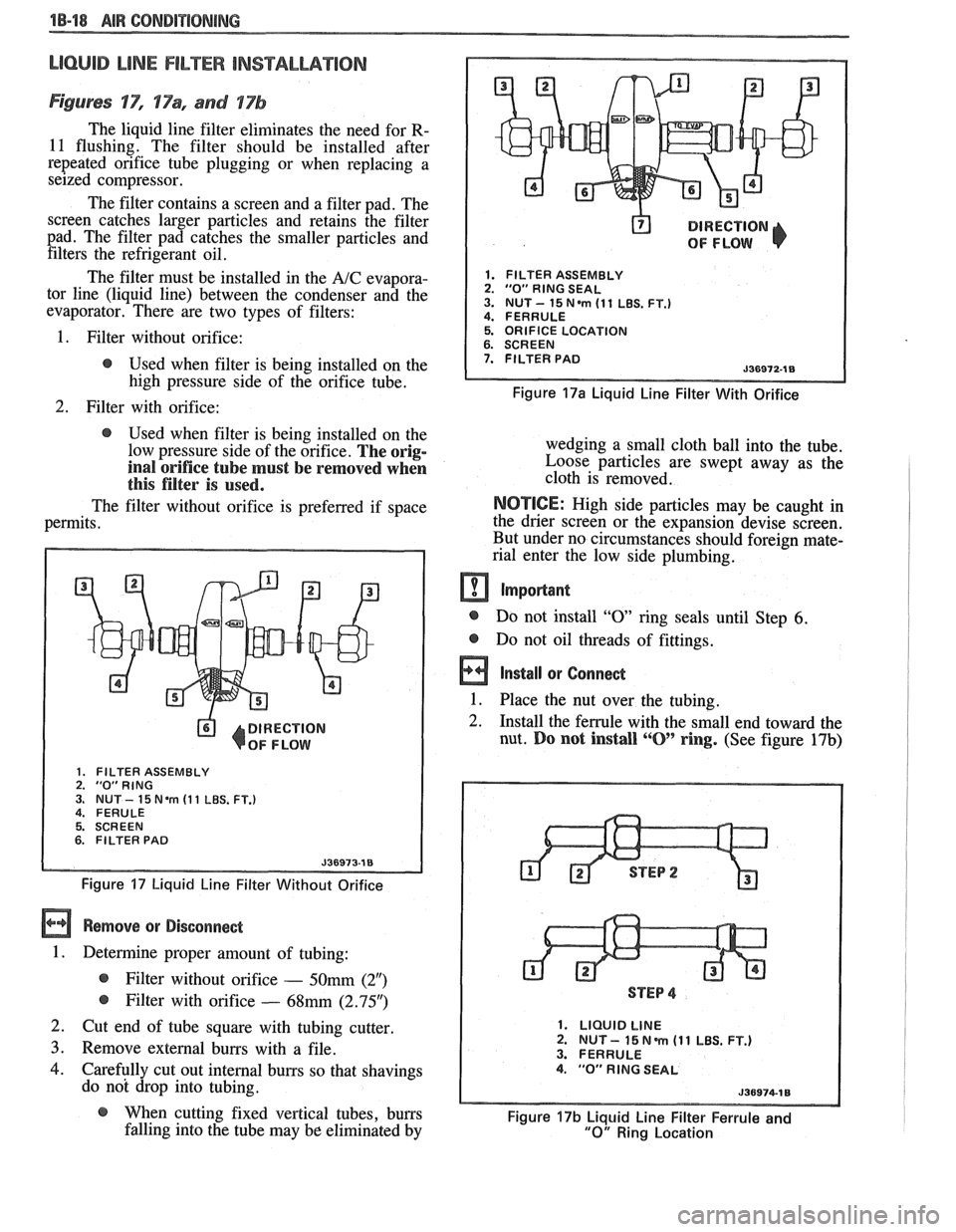
Figures 'IT", 17% and 17b
The liquid line filter eliminates the need for R-
11 flushing. The filter should be installed after
repeated orifice tube plugging or when replacing a
seized compressor.
The filter contains a screen and a filter pad. The
screen catches larger particles and retains the filter
pad. The filter pad catches the smaller particles and filters the refrigerant oil.
The filter must be installed in the
A/C evapora-
tor line (liquid line) between the condenser and the
evaporator. There are two types of filters:
@ DIRECTION
OF FLOW
1. FILTER ASSEMBLY 2. "0" RlNG SEAL 3. NUT- 15N.m (11 LBS. FT.) 4. FERRULE
1. Filter without orifice: 5. ORIFICE LOCATION
@ Used when filter is being installed on the 7. FILTER PAD
high pressure side of the orifice tube. Figure 17a Liquid Line Filter With Orifice
2. Filter with orifice:
@ Used when filter is being installed on the
low pressure side of the orifice.
The orig-
inal orifice tube must be removed when
this filter is used.
The filter without orifice is preferred if space
permits.
DIRECTION
OF FLOW
1. FILTER ASSEMBLY 2. "0"RING 3. NUT - 15 Nem (1 1 LBS. FT.) 4. FERULE
5. SCREEN
6. FILTER PAD
Figure 17 Liquid Line Filter Without Orifice
Remove or Disconnect
1. Determine proper amount of tubing:
@ Filter without orifice - 50mm (2")
@ Filter with orifice - 68mm (2.95")
2. Cut end of tube square with tubing cutter
3. Remove external burrs with a file.
4. Carefully cut out internal burrs so that shavings
do not drop into tubing. wedging a small cloth ball
into the tube.
Loose particles are swept away as the
cloth is removed.
NOTICE: High side particles may be caught in
the drier screen or the expansion devise screen.
But under no circumstances should foreign mate-
rial enter the low side plumbing.
m Important
@ Do not install "0 ring seals until Step 6.
@ Do not oil threads of fittings.
a Install or Connect
1. Place the nut over the tubing. -
2. Install the ferrule with the small end toward the
nut.
Do not install ""0' ring. (See figure 17b)
STEP 4
1. LIQUID LINE 2. NUT - 15 N m (1 1 LBS. FT.) 3. FERRULE 4. "0" RlNG SEAL
@ When cutting fixed vertical tubes, burrs Figure 17b Liquid Line Filter Ferrule and falling into the tube may be eliminated by "0" Ring Location
Page 348 of 1825
ENGINE GENERAL INFORMATION 6-3
B, Section 6E2 - Fuel Injection (TBI)
B, Section 6E3 - Fuel Injection (Ported)
ENGINE MECHANICAL DIAGNOSIS
The following diagnostic information covers common problems and possible causes. When
the proper diagnosis is made, the problem should be corrected by adjustment, repair or part
replacement as required. Refer to the appropriate section of the manual for these procedures.
EXCESSIVE OIL LOSS
B, External oil leaks. Tighten bolts and/or replace o Continuous high speed driving, and/or severe
gaskets and seals as necessary. usage
such as trailer hauling, will normally cause
decreased oil mileage.
e Improper reading of dipstick. Check oil with car PCV system malfunctioning. on a level surface and allow adequate drain-down Valve guides and/or valve stem seals worn, or time.
seals omitted. Ream guides and install oversize
service valves and/or new valve stem seals.
Improper Use S.A'E' Piston rings broken, worn, or not seateded. Allow viscosity for prevailing temperatures. See
adequate time for rings to seat. Replace broken
Owner's Manual for proper specifications.
or worn rings, as necessary.
Piston improperly installed or misfitted.
LOW OIL PRESSURE
Slow idle speed. Set idle speed to correct
specification, if not ECM controlled.
Incorrect, or malfunctioning, oil pressure switch.
Incorrect, or malfunctioning, oil pressure gage.
Replace with proper gage.
.*
Improper oil viscosity, or diluted oil. install oil of
proper viscosity for expected temperature, or
install new oil if diluted with moisture or
unburned fuel mixtures.
o Oil pump worn or dirty.
e Plugged oil filter.
e Oil pickup screen loose or plugged.
B, Hole in oil pickup tube.
e Excessive bearing clearance. Replace if necessary.
o Cracked, porous or plugged oil galleys. Repair or
replace block.
o Galley plugs missing or misinstalled. Install
plugs, or repair as necessary.
VALVE TRAIN NOISE
e Low oil pressure. Repair as necessary. (See o Broken valve spring.
preceding diagnosis for low oil pressure.)
o Sticking valves.
o Loose rocker arm attachments. Inspect and B, Lifters worn, dirty, or defective. Clean, inspect,
test and replace as necessary.
repair as necessary.
o Camshaft worn, or poor machining. Replace
o Worn rocker arm and/or pushrod. camshaft.
B, Worn valve guides.
ENGINE KNOCK DIAGNOSIS
KNOCKS COLD AND CONTINUES FOR TWO TO THREE MINUTES
INCREASES
WITH TORQUE
o Vacuum operated EFE engines may have valve o Excessive piston to bore clearance. Replace
knock. Replace EFE valve. piston.
e Flywheel contacting splash shield. Reposition
splash shield.
e Loose or broken balancer or drive pulleys.
Tighten, or replace as necessary. Cold engine piston knock usually
disappears when the cylinder is grounded
out. Cold engine piston knock which
disappears in 1.5 minutes should be
considered acceptable.
Page 353 of 1825
6A2-2 2.8 LITER V-6
EXHAUST MANIFOLDS
The exhaust manifolds are cast nodular iron.
ENGINE LUBRICATION (FIGURES 6A2.1 THRU
6A2-4)
Full pressure lubrication, through a full flow oil
filter is furnished by a gear type oil pump. Oil is drawn
up through the pick up screen and tube and passed
through the pump to the oil filter.
The oil filter is a full flow paper element unit. An
oil filter by-pass is used to ensure adequate oil supply
should the filter develope excessive pressure drop. The
by-pass is designed to open at 69-83
kPa.
From the filter, oil is routed to the main oil
gallery, rifle drilled above the camshaft to the left of the
camshaft centerline. This gallery supplies the left bank
hydraulic lifters with oil. From
the left gallery oil is directed, by means of
interesting passages to the camshaft bearings and right
oil gallery.
The hydraulic lifters pump oil up through the
push rods to the rocker arms. Oil draining back from
the rocker arms is directed, by cast dams which are
part of the crankcase casting, to supply the camshaft
lobes.
The passages supplying oil to the camshaft
bearings also supply the crankshaft main bearings
through intersecting vertical drilled holes. Oil from the
crankshaft main bearings is supplied to the connecting
rod bearings by means of intersecting passages drilled
in the crankshaft.
Oil also drains past specific hydraulic lifter flats
to oil camshaft .lobes directly.
The front cam bearing has a
.25mm deep slot on
its outside diameter to supply oil to the cam sprocket
thrust face.
Page 367 of 1825
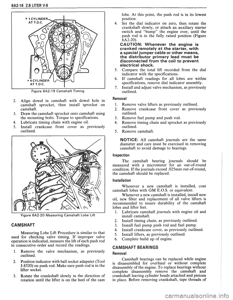
6A2-16 2.8 LITER V-6
Figure 6A2-19 Camshaft Timing
2. Align dowel in camshaft with dowel hole in
camshaft sprocket, then install sprocket on
camshaft.
3. Draw the camshaft sprocket onto camshaft using
the mounting bolts. Torque to specifications.
4. Lubricate timing chain with engine oil.
5. Install crankcase front cover as previously
outlined.
Figure 6A2-20 Measuring Camshaft Lobe Lift
CAMSHAFT
Measuring Lobe Lift Procedure is similar to that
used for checking valve timing. If improper valve
operation is indicated, measure the lift of each push rod
in consecutive order and record the readings.
1. Remove the valve mechanism, as previously
outlined.
2. Position
indicator with ball socket adapater (Tool
5-8520) on push rod. Make sure push rod is in the
lifter socket.
3. Rotate the crankshaft slowly in the direction of
rotation until the lifter is on the heel of the cam lobe.
At this point, the push rod is in its lowest
position.
4. Set the dial indicator on zero, then rotate the
crankshaft slowly, or attach an auxiliary starter
switch and "bump" the engine over, until the
push rod is in the fully raised position (Figure
6A2-20).
CAUTION: Whenever the engine is
cranked remotely at the starter, with
a special jumper cable or other means,
the distributor primary lead must be
disconnected from the coil to prevent
electrical shock.
5. Compare the total lift recorded from the dial
indicator with the specifications.
6. If camshaft readings for all lobes are within
specifications, remove dial indicator assembly.
7. Install and adjust valve mechanism, as previously
outlined.
Removal
1. Remove valve lifters as previously outlined.
2. Remove crankcase front cover as previously
outlined.
3. Remove fuel pump and push rod.
4. Remove timing chain and sprocket as previously
outlined.
5. Remove camshaft.
NOTICE: All camshaft journals are the same
diameter and care must be exercised in removing
camshaft to avoid damage to bearings.
Inspection
The camshaft bearing journals should be
measured with a micrometer for an out-of-round
condition. If the journals exceed
.025mm out-of-round,
the camshaft should be replaced.
Installation
Whenever a new camshaft is installed, coat
camshaft lobes with
GM E.O.S, or equivalent.
Whenever a new camshaft is installed, install new
oil, new filter and replacement of all valve lifters is
recommended to insure durability of the camshaft
lobes and lifter feet.
1. Lubricate camshaft journals with engine oil and
install camshaft.
2. Install timing chain, as previously outlined.
3. Install fuel pump push rod and fuel pump.
4. Install crankcase cover, as previously outlined.
5. Install
lifters, as previously outlined.
6. Complete build up of engine.
CAMSHAFT BEARINGS
Removal
Camshaft bearings can be replaced while engine
is disassembled for overhaul or without complete
disassembly of the engine. To replace bearings without
complete disassembly remove the camshaft and
crankshaft leaving cylinder heads attached and pistons
in place. Before removing crankshaft, tape threads of
Page 380 of 1825
V-8 ENGINE BA3-1
SECVON 6A3
TER V8 V N CODE E
TER V8 V N CODE F
TER V8 V N CODE 8
CONTENTS
GENERAL DESCRIPTION .......................... 6A3- 1
ENGINE LUBRICATION .......................... 6A3-2
ON-VEHCILE SERVICE ............................... 6A3-5
...................................... Powertrain Mounts 6A3-5
Intake Manifold ........................................... 6A3-6
Dipstick Tube .............................................. 6A3-7
Exhaust Manifold ........................................... 6A3-7
........................................ Rocker Arm Cover 6A3-8
Rocker Arm and Push Rods ...................... 6A3-8
Valve Stem Oil Seal and/or
Valve Spring
................................................ 6A3-9
Valve Lifters .................................................. 6A3- 10
............................. Cylinder Head Assembly 6A3- 1 1
...................................... Rocker Arm Studs 6A3- 14
...................................... Valve Guide Bores 6A3- 14
Valve Seats .................................................. 6A3- 14
Valves ........................................................... 6A3- 15
Torsional Damper ........................................ 6A3- 15
.
............................. Crankcase Front Cover .... 6A3- 1 5
Oil Seal (Front Cover) ................................... 6A3- 16
Camshaft ...................................................... 6A3- 16
Camshaft Bearings ............................. .. ....... 6A3- 17
Oil Pan ......................................................... 6A3- 18
..................................................... Oil Pump 6A3- 18
............................. Connecting Rod Bearings 6A3- 19
.............................................. Main Bearings 6A3-20
........................................... Rear Main Seal 6A3-22
........... Connecting Rod & Piston Assemblies 6A3-23
............................................ Cylinder Block 6A3-26
............................... Oil Filter Bypass Valve 6A3-27
.......................................... Engine Assembly 6A3-27
................................................... Crankshaft 6A3-28
..................... Sprocket or Gear Replacement 6A3-28
......................................... SPECIFICATIONS 6A3-28
GENERAL DESCRIPTION
CYLINDER BLOCK CAMSHAFT AND DRIVE
The cylinder block is made of cast iron and has The
cast iron camshaft is supported by 5 bearings
8 cylinders arranged in a "V" shape with 4 cylinders and
is chain driven. A steel crankshaft sprocket drives
in each bank.
5 main bearings support the crankshaft the
timing chain which in turn drives the camshaft
which is retained by bearing caps that are machined through a cast iron 'procket.
with the block for proper alignment and clearances.
Cam lobes are ground, hardened and tapered
Cylinders are completely encircled by coolant Jackets, with the high side toward the rear. This, cou~led with
CYLINDER HEAD a sphericalYface on the lifter, causes the "alve lifters to
rotate.
Camshaft bearings are lubricated through oil
The cast iron cylinder heads feature individual
holes which intersect the main oil gallery. The main oil intake and exhaust Ports for each cylinder. Valve gallery is rifle drilled down the center of the block, guides are integral, and rocker arms are retained on above the individual pressed studs.
CRANKSHAFT AND BEARINGS
The crankshaft is cast nodular iron and is
supported by five main bearings
#5 is the end thrust
bearing.
Main bearings are lubricated from oil holes which
intersect the camshaft bearings. The camshaft bearings
are fed oil by the main oil gallery which is rifle drilled
down the center of the block, above the camshaft. Two
additional oil galleries are on either side of the main oil
gallery to provide an oil supply for the hydraulic lifters.
PISTONS AND CONNECTING RODS
The pistons are made of cast aluminum alloy
using two compression rings and one oil control ring.
Piston pins are offset 1/16"
(1.6mm) toward the thrust
side (right hand side) to provide a gradual change in
thrust pressure against the cylinder wall as the piston
travels its path. Pins are Chromium steel and have
a
floating fit in the pistons They are retained in the
connecting rods by a press fit. Connecting rods are
made of forged steel. Full pressure lubrication
is
directed to the connecting rods by drilled oil passages
from the adjacent main bearing journal.