gas type PONTIAC FIERO 1988 Service Repair Manual
[x] Cancel search | Manufacturer: PONTIAC, Model Year: 1988, Model line: FIERO, Model: PONTIAC FIERO 1988Pages: 1825, PDF Size: 99.44 MB
Page 20 of 1825
F CARLINE
ITEM 10
TransmissionRransaxle Service
The manual transmission or transaxle fluid does not
require changing. (Corvette only.) Change fluid in over-
drive unit every 30,000 miles (50 000 km).
For automatic transmissions or transaxles, change
both the fluid and filter every 15,000 miles (25 000 km) if
the car is mainly driven under one or more of these
conditions:
@ In heavy city traffic where the outside temperature
regularly reaches 90°F (32°C) or higher.
@ In hilly or mountainous terrain.
@ Frequent trailer pulling.
@ Uses such as found in taxi, police car or delivery
service.
If you do not use your car under any of these condi-
tions, change both the fluid and filter every 100,000 miles
(160 000 km). See you Owner's Manual for further
details.
ITEM 11
Spark Plug Service*
Replace spark plugs with type listed in your Owner's
Manual.
ITEM 12
Spark Plug Wire Inspection*
Clean wires and inspect for burns, cracks or other dam-
age. Check the wire boot fit at distributor and at spark plugs.
Replace wires as needed.
ITEM 13
Positive Crankcase Ventilation (PCV) Valve
Inspection*
Inspect valve for proper function. Replace valve if
necessary as well as any worn, plugged or collapsed
hoses.
ITEM 14
EGR System Service*
Conduct EGR System Service as referenced in the
EGR System Chart shown in the appropriate 6E Section.
Also, refer to your GM maintenance schedule booklet for
specific applications.
ITEM 15
Air Cleaner and PCV Filter Replacement*
On 1.6 and 2.0 liter engines, replace every 50,000
miles (80 000 km). On all other engines, replace every
30,000 miles (50 000 km). Replace more often under
dusty conditions. Ask your dealer for the proper replace-
ment interval for your driving conditions.
MAINTENANCE AND LUBRICATION 08-3
ITEM 16
Engine Timing Check*
Adjust timing to underhood label specifications. If
no specifications are shown, no adjustment is needed.
ITEM 17
Fuel Tank, Cap and Lines Inspection*
Inspect fuel tank, cap and lines (including fuel rails
and injection assembly, if so equipped) for damage or
leaks. Inspect fuel cap gasket for an even filler neck
imprint or any damage. Replace parts as needed.
ITEM 18
Thermostatically Controlled Air Cleaner
Inspection*
If your car is equipped, inspect all hoses and ducts
for proper hookup. Make sure valve works properly.
OWNER INSPECTIONS AND SERVICES
Listed below are inspections and services which
should be made by either you or a qualified technician at
the intervals shown to help ensure proper safety, emission
performance and dependability of your car. Take any
problems promptly to your dealer or another qualified
technician for service advice. Whenever repairs are neces-
sary, have them completed at once. For your safety and
that of others, any safety-related parts that could have
been damaged in an accident should be inspected and all
needed repairs should be done before operating your car.
Be sure to use the proper fluids and lubricants as shown in
Figure OB-2.
WHILE OPERATING YOUR VEHICLE
Automatic transmissionltransaxle shift indi-
cator operation - Make sure the indicator points to the
gear chosen.
Horn operation - Blow the horn occasionally to
make sure it works. Check all button locations.
I
Brake system operation -- Be alert to abnormal
sounds, increased brake pedal travel or repeated pulling to
one side when braking. Also, if a brake warning light
comes on or flashes, or the anti-lock warning light (if
equipped) comes on or remains on, something may be
wrong with part of the brake system. Have it inspected and
repaired at once.
Exhaust system operation - Be alert to any
changes in the sound of the system or any smell of fumes.
These are signs the system may be leaking or overheating.
.
Have it inspected and repaired at once. Also see "Engine
Exhaust Gas Caution (Carbon Monoxide)" and "Catalytic
Converter" in your Owner's Manual.
*An Emission Control Service
Page 24 of 1825
HEATING AND VENTILATION 1A-1
SECTION 1A
NG AND VENT
CONTENTS
General Description ................................. 1A-1
Diagnosis - Heater Trouble ...................... 1A-5
Insufficient Heating or Defrosting .............. 1A-5
Blower Electrical ......................................... 1A-7
....... Improper Air DeliveryINo Mode Shift 1 A-8
Too Much Heat .......................................... 1A-9 ....................................................... Controls 1A-10 ............................................... Blower Noise 1A-11
....................................... On-Vehicle Sewice 1A-13
.......................... Heater Control Assembly 1 A- 13
....................................... Blower Switch 1A- 13
.................................. Temperature Cable
1 A- 13
.......................................... Heater Core 1 A- 13
................................. Vent Control Cable 1 A- 13
Lower Heater Outlet
................................ 1A-14
........................................ Blower Motor 1A-14
GENERAL DESCRIPTION
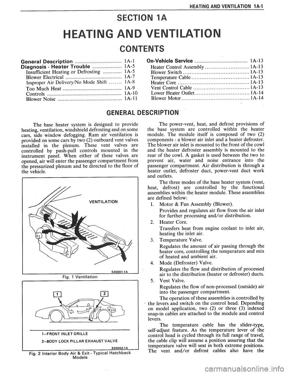
The base heater system is designed to provide
heating, ventilation, windshield defrosting and on some
cars, side window defogging. Ram air ventilation is
provided on some cars by two (2) outboard vent valves
installed in the plenum. These vent valves are
controlled by push-pull controls mounted in the
instrument panel. When either of these valves are
opened, air will enter the passenger compartment from
the pressurized plenum and be directed to the floor of
the vehicle.
/& VENTILATION
1-FRONT INLET GRILLE
2-BODY LOCK PILLAR EXHAUST VALVE
Fig. 2 Interior Body Air & Exit - Typical Hatchback Models
The power-vent, heat, and defrost provisions of
the base system are controlled within the heater
module. The module itself is composed of two (2)
components
- a blower air inlet and a heater defroster.
The blower air inlet is mounted to the front of the cowl
and the heater defroster assembly is mounted to the
rear of the cowl. A gasket is used between the two to
prevent air, water and noise entrance into the
passenger compartment. Air distribution is through a
heater outlet, defroster duct, power-vent duct work
and outlets.
The three modes of the base heater system (vent,
heat, defrost) are controlled by the functional
assemblies within the heater module. These assemblies
are defined below:
1. Motor & Fan Assembly (Blower).
Provides and regulates air flow from the air inlet
for further processing and/or distribution.
2. Heater Core.
Transfers heat from engine coolant to inlet air,
heating the inlet air.
3. Temperature Valve.
Regulates the amount of air passing through the
heater core, controlling the temperature and mix
of heated and ambient air.
4. Mode (Defroster) Valve.
Regulates the flow and distribution of processed
air to the distribution (heater or defroster) ducts.
5. Vent Valve.
Regulates the flow of non-processed (outside) air
into the passenger compartment.
The operation of these assemblies is controlled by
the levers and switch on the control head. Depending
on model application, two (2) or three
(3) indexed
snap-in cables are attached to the module and control
levers.
The temperature cable has the slider-type,
self-adjust feature. As the temperature lever of the
control head is cycled through its full range of travel,
the cable clip will assume a position assuring that the
temperature valve will seat in both extreme positions.
The vent and/or defrost cables also have the
Page 113 of 1825
866 CHASSIS SHEET METAL
PROPER IDENTIFICATION AND CDAlrUmNG
OF INTERIOR PWSTIC TRlM
Interior plastic trim parts are normally supplied
in only one color. It is necessary to paint most parts.
Most vinyl headlinings and soft vinyl seat cushion and
hack cover assemblies are furnished in colors.
Instructions on how to identify each paintable
plastic part, and how to apply the available paint
materials are as follows:
Paintable plastic trim components, as used on
General Motors interiors, can be divided into three
general types:
@ Polypropylene Plastic
@ ABS Plastic
@ Vinyl Plastic
Excluding the soft vinyl seat cushion and seat
back trim cover assemblies, the plastic used most
widely on the interior of bodies is "POLYPROPYL-
ENE" and, as noted later, requires special refinishing
materials and procedures. Therefore, it is important
for a painter to be able to identify each plastic in order
to paint it satisfactorily. The purpose of the following
tests is to determine the identity of a given plastic so
that the proper paint procedure and refinishing mate-
rials will be used.
TEST PROCEDURE
Polypropylene, ABS or Vinyl Plastic
From a hidden backside portion of the part,
remove a sliver of plastic with a sharp blade.
Holding the sliver with needle-nose pliers, put it
to a flame and observe whether or not any
smoke is given off when burning.
ABS PLASTIC will give off a HEAVY BLACK
SMOKE, and POLYPROPYLENE will burn
clean.
However, if a sliver gives off OTHER THAN
HEAVY BLACK SMOKE, it is either DIRTY
POLYPROPYLENE OR IS VINYL. To deter-
mine which it is, the following burn test should
be made with the hot tip of a clean copper wire.
Heat the tip of the copper wire to a "red-glow"
with a propane (gas) torch.
Touch the heated wire to a hidden portion of the
plastic in question, to get some of the plastic on
the wire.
Return the wire, with its
now plastic-coated tip,
to the flame and observe for flame color.
If the flame given off from the wire is of the
GREEN-TURQUOISE-BLUE RANGE, then
the PLASTIC IS VINYL. (Any other color
flame would indicate the material is dirty poly-
propylene.
)
PAINWING lNTERiOR PWSTIC PARTS
Before painting, always check the body number
plate of the car for the
correct trim code color number
for that model year. The body number plate is located
on the upper horizontal surface of the shroud. Interior
color is color keyed to this "Trim Combination Num-
ber" (TR) on the body plate. Each paint supplier pro-
vides an interior color chart which identifies their
stock number, color name, gloss factor and trim com-
bination number for each "conventional" interior
color. Charts listing "vinyl" interior colors are also
provided.
"CONVENTIONAL" interior acrylic colors are
designed for use only on hard trim parts, such as:
1. Steel parts (primer or sealer required on new
service parts).
2. Hard POLYPROPYLENE plastic ("Special
Primer" required
- See GM Parts Catalog).
3. Hard ABS plastic (NO primer necessary).
"VINYL" interior colors are designed for soft
and/or flexible trim parts, such as instrument panel
cover pad assemblies, upper door trim pad assem-
blies, molded headlining panels, head rests and assist
handles. These colors require a final top coat of clear
vinyl spray, with instrument panel pads requiring a
"nonglare" clear final top coat. Other trim parts
require a degree of gloss to match similar adjacent
parts.
POLYPROPYLENE PUSTIC PARTS
The system for painting polypropylene parts
involves the use of a special primer. It is essential that
the service part be first primed with a coating of spe-
cial POLYPROPYLENE PRIMER (Detroit
Autobody
#PP-2250, or equivalent) according to factory recom-
mendations on the can. Because the primer acts as a
bonding agent between the plastic and acrylic lacquer, failure to use it will result in color coat "lifting"
and/or
"peeling" problems. After priming, the part can be
color coated with conventional interior acrylic
lacquer,
PROCEDURE
1. Wash part thoroughly with a cleaning solvent ("Acryli-Clean," "Prep-Sol," or equivalent) that
will not leave any greasy film.
2. Apply a thin, wet coat of the special polypropyl-
ene primer according to label directions on can.
Wetness of primer is best determined by observ-
ing gloss reflection of spray application in ade-
quate lighting. Be sure primer application
includes all edges. Allow
the primer to flash dry
ONE (1) MINUTE MINIMUM and TEN (10)
MINUTES MAXIMUM. (If the flash period
before color coating should extend beyond ten
minutes, the primer MUST be reapplied to
avoid previously mentioned adhesion
problems
.)
Page 254 of 1825
REAR AXLE 481-1
SECTION 4B4
BORG WARNER REAR AXLE
NOTICE: All rear axle attaching fasteners are an
necessary. Do not use a replacement part of lesser
important part in that they could affect the
quality or substitute design. Torque values must
performance of vital parts and systems, and/or
be used as specified during reassembly to assure
could result in major repair expense. They must
proper retention of all parts. (There is to be no
be replaced with one of the same part number or
welding as it may result in extensive damage and
with an equivalent part if replacement becomes
weakening of the metal.)
CONTENTS
General Description ............................... 4B 1- I
......... Standard Rear Axle ................... ..... 4B 1 - 1
General Information ............................. .... 4B 1- 1
Limited-Slip Rear Axle .............................. 4B 1-2
Operation
............................................ 4B 1-3
Diagnosis and Testing .......................... 4B 1-2
Axle Noises
..................... .... .................. 4B 1-2
Gear Noise
................................... .... .. 4B 1-4
Bearing Noise
......................... ...... ... 4B 1-4
Rear Wheel Bearing Noise ..................... 4B 1-4
Knock At Low Speeds
....................... ..... 4B 1-4
Backlash Clunk
................................... 4B 1-4
Diagnosis
................................................ 4B 1-4
Pre-Repair Investigation and Trouble
Diagnosis
....................... .. .................... 4B 1-4
...................................... On-Vehicle Sewice 4B 1-7
Carrier Cover and Gasket .......................... 4B 1-7
.............. Axle Shaft ......................... ....., 4B 1-7
Tooth Contact Pattern Test
................... 4B 1-8
Procedure
.................... .. ...................... 4B 1-8
Effects of Increasing Load on
Teeth Contact Pattern
......................... 4B 1-8
Adjustments Affecting Tooth
................................................ Contact 4B 1-8
Effects of Pinion
Postion on Tooth Pattern
............................................... 4B
1-8
Pinion Oil Seal and Companion
Flange Replacement
................... .. ...... 4B 1-8
Rear Wheel Bolt
........................................ 4B 1 - 10
Rear Axle Assembly
................................... 4B I - 10
Unit Repair
............................................... 4Bl-1 1
Drain Rear Axle Assembly ........................ 4B I - I I
Differential Assembly ............................. 4B 1 - 1 1
Hypoid Pinion & Pinion Bearings .......... 4B 1- I I
Four Pinion Standard Differential
Assembly
....................... ... ........... 4B 1 - 1 3
Inspection
............................................ 4B 1 - I:!
Differential Assembly .......................... 4B 1 - 14
Differential Bearing Preload Spacer
................... ...................... Selection .. 4B I - 11
.................................................. Pinion 4B 1 - 15
Operation of Limited Slip Rear Axle
........................................... (Cone Type) 4B 1 - 17
Checking Limited-Slip Function
............ 4B 1 - 17
......................... Limited Slip Differential 4B 1 - 18
.............. Disassembly Inspection Chart 4B
1- 18
......................... Limited Slip Differential 4B I - 1 X
............................................. Specifications
4B 1- 19
Axle Code Identification Chart
............ 4B 1-19
............................................. Special Tools 4B 1-20
GENERAL DESCRIPTION
STANDARD REAR AXLE All parts necessary to transmit power from the
propeller shaft to the rear wheels are enclosed in a
The rear axle assembly is of the semi-floating type salisbury type axle housing (a carrier casting with tubes
in which the car weight is carried on the axle housing.
pressed and welded into the carrier to form a complete The rear axle assembly is designed for use with an open carrier and tube assembly). A removable steel cover drive line and coil springs. The rear axle has a hypoid bolted to the rear of the carrier permits service of the type ring gear and pinion with the centerline of the rear axle without removing the entire assembly from
pinion gear below the centerline of the ring gear.
the car.
GENERAL INFORMATION
NOTICE: Most rear axle service repairs can be
Two pre-loaded tapered roller bearings support the
made with the rear axle assembly in the car, by
hypoid pinion gear in the carrier. The inner race of the
raising the rear end of the car with the rear axle
rear bearing is a tight press fit on the pinion stem. The
hanging on the shock absorbers.
inner race of the front bearing combines a light press
fit to a close sliding fit on the pinion flange end of the
A universal joint connects the rear end of the pinion stem. The outer race of each bearing is pressed
propeller shaft to a companion flange having a splined against a shoulder recessed in the carrier. Tightening
end which fits over and drives the
hypoid pinion gear. the pinion nut compresses a collapsible spacer which
Page 264 of 1825
REAR AXLE 4Bl-I I
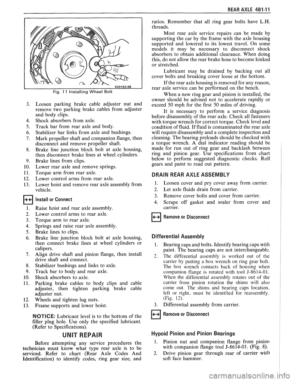
Fig. 11 Installing Wheel Bolt
Loosen parking brake cable adjuster nut and
remove two parking brake cables from adjuster
and body clips.
Shock absorbers from axle.
Track bar from rear axle and body.
Stabilizer bar links from axle and bushings.
Mark propeller shaft and companion flange, then
disconnect and remove propeller shaft.
Brake line junction block bolt at axle housing,
then disconnect brake lines at wheel cylinders.
Brake lines from clips.
Lower rear axle and remove springs.
Torque arm from rear axle.
Lower control arms from rear axle.
Lower hoist and remove rear axle assembly from
vehicle.
Install or Connect
Raise hoist and rear axle assembly.
Lower control arms to rear axle.
Torque arm to rear axle.
Springs and raise rear axle assembly.
Brake lines to clips.
Brake line junction block bolt at axle housing,
then connect brake lines at wheel cylinders or
calipers.
Align drive shaft and pinion flange, then install
drive shaft and connect.
Stabilizer bushings and links to axle.
Track bar to body and rear axle.
Shock absorbers to axle.
Parking brake cables to body clips and cable
adjuster, then tighten parking brake cable
adjuster nut.
Wheels and tighten lug nuts.
Frame supports and lower hoist.
NOTICE: Lubricant level is to the bottom of the
filler plug hole. Use only the specified lubricant.
(Refer to Specifications).
Before attempting any service procedures the
technician must know what type rear axle is to be
serviced. Refer to chart (Rear Axle Codes And
Identification) to identify codes, ring gear size, and ratios.
Remember that all ring gear bolts have
L.H.
threads.
Most rear axle service repairs can be made by
supporting the car by the frame with the axle housing
supported and lowered to its lowest travel. On some
models it may be necessary to disconnect shock
absorbers to obtain additional clearance. When doing
this, do not allow the rear brake hose to become
kinked
or stretched.
Lubricant may be drained by backing out all
cover bolts and breaking cover loose at the bottom.
If the rear axle housing is removed for any reason,
rear axle service can be performed on the bench.
When a new ring gear and pinion is installed, the
owner should be advised not to accelerate rapidly or
exceed 50 mph for the first 50 miles of driving.
It is necessary to perform a service diagnosis
before disassembly of the rear axle. Check all fasteners
with torque wrench for correct torque. Check level and
condition of fluid.
If fluid is contaminated the rear axle
will require disassembly and a complete inspection and
cleaning. The bearing preloads should be checked with
a torque wrench. A dial indicator reading should be
made for run out of ring gear and backlash between
ring and pinion gear. Use specifications from chart
below to perform suggested diagnostic checks. Roll
gears and paint to read out pattern.
DRAIN REAR AXLE ASSEMBLY
1. Loosen cover and pry cover away from carrier.
2. Let axle fluids drain from carrier.
3. Remove cover bolts and cover from carrier.
4. Scrape off gasket and sealer from cover and
carrier.
Remove or Disconnect
Differential Assembly
1. Bearing caps and bolts. Identify bearing caps with
paint. The bearing caps are not interchangeable.
2. The differential assembly is worked out of the
carrier by putting a box wrench on ring gear bolt.
The box wrench contacts back of housing when
companion
tlange is rotated with tool 3-8614-01.
When the differential assembly rotates out of the
carrier from pinion rotation the shims will also
come out. The shims and bearing caps location,
left or right, must be identified for reassembly.
(Fig. 12).
3. Differential assembly from carrier.
Remove or Disconnect
Hypoid Pinion and Pinion Bearings
1. Pinion nut and companion flange from pinion
with companion flange tool 5-8614-01. (Fig. 8).
2. Drive pinion gear through rear of carrier with
soft face hammer.
Page 274 of 1825
REAR AXLE 4B-1
SECTION 4B
REAR AXLE
NOTICE: All rear axle attaching fasteners are an necessary.
Do not use a replacement part of lesser
important part in that they could affect the quality
or substitute design. Torque values must
performance of vital parts and systems, and/or be
used as specified during reassembly to assure
could result in major repair expense. They must proper retention
of all parts. (There is to be no
be replaced with one of the same part number or welding
as it may result in extensive damage and
with an equivalent part if replacement becomes weakening
of the metal.)
CONTENTS
General Description .................................. 4B-1
Standard Rear Axle ................... .. ............ 4B- 1
Diagnosis and Testing ............................... 4B-1
Axle Noises ......................... .. ................ 4B-3
Gear Noise ...................... .. .................. 4B-3
Bearing Noise ........................................ 4B-3
Rear Wheel Bearing Noise ....................... 4B-3
Knock at Low Speeds ............................. 4B-3
Backlash Clunk ...................................... 4B-3
Rear Axle Standard and Limited Slip .......... 4B-3
Pre-Repair Investigation and Trouble
Diagnosis
................................................. 4B-4
Gear Tooth Nomenclature ....................... 4B-4
Tooth Contact Pattern Test ..................... 4B-4
Effects of Increasing Load on
Teeth Contact Pattern
.......................... 4B-4
Adjustments Affecting Tooth
Contact
.................................................. 4B-6
Effects of Pinion Position on Tooth
Pattern
................... ... .................... 4B-6
General information ....................... .. ..... 4B-8
Limited-Slip Rear Axle ............................... 4B-8
On-Vehicle Service ............................. .. ....... 4B-8
Carrier Cover and Gasket .......................... 4B-8
............................................. Axle Shaft 4B-8
Oil Seal and/or Bearing (With
Axle Shaft Removed)
............................. 4B-9
........................................ Pinion Oil Seal 4B-9
........................................... Pinion Flange 4B- 10
..................................... Rear Wheel Bolt 4B- 1 1
.................................................... Unit Repair 4B-1 1
..................................... Rear Axle Assembly 4B- 1 1
Disassembly of Rear Axle
............................................... Assembly 4B- 1 1
.. ..................................... Case Assembly ... 4B- 12
Drive Pinion, Bearing and Races ............. 4B- 12
............................... Bearing Replacement 4B- 12
...................... Setting Drive Pinion Depth 4B- 13
........................................ Rear Axle Case 4B- 14
Side Bearing Preload Adjustment ............ 4B- 15
.................................................. Drive Pinion 4B- 16
Rear Axle Backlash Adjustment .............. 4B- 17
........... Limited Slip Rear Axle (Cone Type) 4B-17
...................................... Auburn Cone Type 4B- 18
.............................................. Specifications 4B- 19
.............................................. Special Tools 4B-20
GENERAL DESCRIPTION
STANDARD REAR AXLE Operation
The rear axle assembly is of the semi-floating type
in which the car weight is carried on the axle housing.
The rear axle assembly is designed for use with an open
drive line and coil springs. The rear axle has a
hypoid
type ring gear and pinion with the centerline of the
pinion gear below the centerline of the ring gear.
All parts necessary to transmit power from the
propeller shaft to the rear wheels are enclosed in a When
the vehicle turns a corner, the outer rear
wheel must turn faster than the inner wheel. The inner
wheel, turning slower than the outer wheel, slows its
differential side gear (as the axle shaft is splined to the
side gear) and the differential pinion gears will roll
around the slowed differential side gear, driving the
other differential side gear and wheel faster.
DIAGNOSIS AND "TESTING
salisbury type axle housing (a carrier casting with tubes Many
noises reported as coming from the rear
pressed and welded into the carrier to form a complete axle assembly actually
originate from other sources
carrier and tube assembly). A removable steel cover such as
tires, road surfaces, wheel bearings, engine,
bolted to the rear of the carrier permits service of the transmission,
muffler or body drumming. A thorough
rear axle without removing the entire assembly from and
careful check should be made to determine the
the car. source
of the noise before disassembling the rear axle.
Page 290 of 1825
REAR AXLE 48-1 7
approached. No further tightening should be
attempted until the pre-load has been checked.
7. Check pre-load by using an inch pound torque
wrench.
NOTICE: After pre-load has been checked, final
tightening should be done very carefully. For
example, if when checking, pre-load was found to
be 0.6
N-m (5 lbs. in.), any additional tightening
of the pinion nut can add many additional pound
inch of torque. Therefore, the pinion nut should be
further tightened only a little at a time and the
pre-load should be checked after each slight
amount of tightening. Exceeding pre-load
specifications will compress the collapsible spacer
too far and require the installation of a new
collapsible spacer.
While observing the preceeding note, carefully set
pre-load at 2.7 to 3.6
N-m (24 to 32 1b.in.) on new
bearings or 1.0 to 1.4
N m (8 to 12 1b.in.) on used
bearings.
8. Rotate pinion several times to assure that
bearings have been seated. Check pre-load again.
If pre-load has been reduced by rotating pinion,
reset pre-load to specifications.
Rear Axle Backlash Adjustment
1. Install rear axle case into carrier, using shims as
determined by the side bearing pre-load
adjustment.
2. Rotate rear axle case several times to seat
bearings, then mount dial indicator. Use a small
button on the indicator stem so that contact can
be made near heel end of tooth. Set dial indicator
so that stem is in line as nearly as possible with
gear rotation perpendicular to tooth angle for
accurate backlash reading.
3. Check backlash at three or four points around
ring gear. Lash must not vary over
.05mm (.002")
around ring gear. Pinion must be held stationary
when checking backlash. If variation is over
.05mm (.002") check for burrs, uneven bolting
conditions or distorted case flange and make
corrections as necessary.
4. Backlash at the point of minimum lash should be
between .13 and
.23mm (.005" and ,009") for all
new gears.
5. If backlash is not within specifications, correct by
increasing thickness of one shim and decreasing
thickness of other shim the same amount. This
will maintain correct rear axle side bearing
pre-load.
For each
.03mm (.001") change in backlash
desired, transfer
.05mm (.002") in shim
thickness. To decrease backlash
.03mm (.00lU),
decrease thickness of right shim .05mm (.002")
and increase thickness of left shim .05mm (.
002 "). To increase backlash .05mm (.002 ")
increase thickness of right shim .10mm (.004")
and decrease thickness of left shim .10mm (.
004"). 6.
When backlash is correctly adjusted, remove both
bearing caps and both shim packs.
Keep packs in their respective position, right or
left side.
Select a shim
.10mm (.004") thicker than the one
removed from the left side, then insert left side
shim pack between the spacer and the left bearing
race. Loosely install bearing cap.
7. Select a shim
.10mm (.004") thicker than the one
removed from right side and insert between the
spacer and the right bearing race. It will be
necessary to drive the right shim into position
(Fig. 614).
8. Torque to 75 Nem (55 1b.ft.).
9. Recheck backlash
and correct if necessary.
10. Install axles (See Rear Axle Installation).
11.
Use sealant 1052366 or cover gasket
only.
Install cover and torque cover bolts to 27
N-m (20 1b.ft.).
12. Fill rear axle to proper level with the specified
lubricant. Refer to specifications.
LIMITED SLIP REAR AXLE (GONE TYPE)
The cone-type limited-slip differential has several
definite operating characteristics. An understanding of
these characteristics is necessary as an aid to diagnosis.
The clutch energizing force comes from the
thrust side of the gears. Consequently, a free spinning
wheel may not have enough resistance to drive torque
to apply the clutch cones. If this occurs, apply the
parking brake a few notches which will provide enough
resistance to energize the clutch cones.
Energizing the clutch cones is independent of
acceleration; therefore, a very slow application of the
throttle on starting is recommended to provide
maximum traction by preventing "break away" of
either rear wheel.
Improper operation is generally indicated by cone
slippage or grabbing. Sometimes this produces a
chatter or whirring sound. However, these sounds do
not always indicate failure as they could be produced
from a lack of proper lubrication. For example, under
certain conditions where one wheel is on
a very slippery
surface and the other on dry pavement, wheel spin can
occur if over acceleration is attempted. Continued
spinning may cause audible noise, such as a whirring
sound, due to the cones lacking sufficient lubricant.
This does not necessarily indicate failure of the unit.
During regular operation (straight ahead driving)
when both wheels rotate at equal speeds, there is an
approximately equal driving force delivered to each
wheel. When cornering, the inside wheel delivers extra
driving force causing slippage in both clutch cones.
Consequently, the operational life of the limited slip
unit is dependent upon equal rotation of both wheels
during straight ahead operation. If wheel rotation for
both rear wheels is not equal during straight ahead
operation, the limited-slip unit will constantly be
functioning as if the vehicle were cornering. This will
impose constant slippage on the clutch cones and will
eventually lead to abnormal wear on the clutch cones.
Therefore, it is important that there be no excessive
differences in the rear wheel tire sizes, air pressures, or
Page 364 of 1825
2.8 LITER V.6 6A2.13
Torque bolts as shown in Figure 6A2-15.
4. Install
push rods and loosely retain with rocker
arms. Make sure lower ends of
pushrods are in
lifter seats.
5. Install intake manifold.
6. Raise vehicle.
7. Install dipstick tube bracket.
8. Connect exhaust pipe
to exhaust manifold flange.
9. Lower vehicle.
10. Adjust
valve lash as previously outlined.
11. Continue
following intake manifold installation
for build up.
Removal (Right)
Remove intake manifold as previously outlined.
Raise vehicle.
Disconnect exhaust pipe.
Drain engine block.
Lower vehicle.
Loosen rocker arms until able to remove push
rod.
Remove serpentine belt.
Remove tensioner.
Remove A.I.R. bracket.
Remove generator bracket.
Remove head bolts.
Remove head.
Installation (Right)
The gasket surfaces on both the head and cylinder
case
deck must be clean of any foreign matter and free
of nicks of heavy scratches. Cylinder bolt threads in the
case and threads on the cylinder head bolts must be
clean. Dirt will affect bolt torque.
1. Place the gasket in position, over the dowel pins,
with the note "This Side Up" showing.
2. Install cylinder head.
3. Coat cylinder head bolt threads with sealer,
#lo52080 or equivalent, and install bolts.
Torque bolts as shown in (Figure
6A2-15).
Install push rods and loosely retain with rocker
arms. Make sure lower ends of push rods are in
lifter seats.
Install intake manifold.
Raise vehicle.
Install exhaust pipe to exhaust manifold flange.
Lower vehicle.
Adjust valve lash as previously outlined.
Install AIR bracket.
Install tensioner.
Install generator bracket.
Continue following intake manifold installation
for build up.
Disassembly
1. With cylinder head removed, remove rocker arm
nuts, balls and rocker arms (if not previously
done).
2. Using tool J-8062, compress the valve springs and
remove valve keys. Release the compressor tool and
remove spring caps, oil shedders, springs and
damper assemblies, then remove oil seals.
3. Remove valves from cylinder head and place
them in a rack so they can be installed in their
original positions.
Cleaning and Inspection
Clean all carbon from combustion chambers and
valve ports using 'tool
5-8089.
Thoroughly clean valve guides using 5-8 10 1.
Clean all carbon and sludge from push rods,
rocker arms and push rod guides.
Clean valve stems and heads on a buffing wheel.
Clean carbon deposits from head gasket mating
surface.
Inspect cylinder head for cracks in the exhaust
ports, combustion chambers, or external cracks
to the water jacket.
Inspect the valves for burned heads, cracked faces
or damaged stems.
NOTICE: Excessive valve stem to bore clearance
will cause high oil consumption and may cause
valve breakage. Insufficient clearance will result in
noise and sticky functioning of the valve and
disturb engine smoothness.
8. Measure valve stem clearance as follows:
a. Clamp
a dial indicator on one side of the
cylinder head. Locate the indicator so that
movement of the valve stem from side to
side (crosswise to the head) will cause direct
movement of the indicator stem. The
indicator stem must contact the side of the
valve stem just above the guide.
b. Drop
the valve head
1.5mm off the valve
seat.
c. Move
the stem of the valve from side to side,
using light pressure, to obtain a clearance
reading. If clearance exceeds specifications,
it will be necessary to ream valve guides for
oversize valves. Service valves are available
in std., 089,
.394 and .775mm O.S. sizes.
9. Check
valve spring tension with tool J-8056,
spring tester. Springs should be compressed to the
specified height and checked against the
specifications chart. Springs should be replaced if
not within 44
N (10 Ibs.) of the specified load
(without dampers).
10. Inspect
rocker arm studs for wear or damage.
ROCKER ARM STUDS
Cylinder heads use threaded rocker arm studs.
Rocker arm studs that have damaged threads should
be replaced with new studs. If, for some reason, the
threads in the head
are damaged or stripped, the head
can be retapped, and a helical type insert added. If such
an insert is not available, the head should be replaced.
VALVE GUIDES
Valves with oversize stems are available in .089,
,394 and ,775mm over sizes. To ream the valve guide
Page 369 of 1825
6A2-18 2.8 LITER V-6
Installation
Clean sealing surfaces on cylinder case and oil
pan.
Install gasket and attach retaining bolts.
Remove jack and lower engine.
Install motor mount through bolts.
Install starter.
Install exhaust pipes.
Install converter dust cover.
Lower vehicle.
Install fan shroud.
Install distributor cap.
Refill crankcase.
Install air cleaner.
Connect battery.
Start engine, check for leaks.
OIL PUMP (FIGURE 6A2-22)
Removal
1. Remove oil pan as previously outlined.
2. Remove pump to rear main bearing cap bolt and
remove pump and extension shaft.
Disassembly
1. Remove
the pump cover attaching bolts and the
pump cover. Mark gear teeth so they may be
reassembled with the same teeth indexing.
2. Remove the idler gear and the drive gear and
shaft from the pump body.
3. Remove the pressure regulator valve retaining
pin pressure regulator spring and valve.
4. If the pickup screen and pipe assembly need
replacing, mount the pump in a soft-jawed vise
and extract pipe from pump cover. Do not disturb
the pickup screen on the pipe. This is serviced as
an assembly.
Cleaning and lnspection
1. Wash all parts in cleaning solvent and dry with
compressed air.
2. Inspect the pump body and cover for cracks or
excessive wear.
3. Inspect pump gears for damage or excessive wear.
The pump gears and body are not serviced
separately. If the pump gears or body are
damaged or worn, replacement of the entire oil
pump assembly is necessary.
4. Check the drive gear shaft for looseness in the
pump body.
5. Inspect inside of pump cover for wear that would
permit oil to leak past the ends of the gears.
6. Inspect the pickup screen and pipe assembly for
damage to screen or pipe.
7. Check the pressure regulator valve for fit.
Assembly
1. If the pickup screen and pipe assembly was
removed, it should be replaced with a new part.
Loss of press fit condition could result in an air
leak and loss of oil pressure. Mount the pump in
a soft-jawed vise, apply sealer to outside diameter of
swaged end of pipe, and using Tool
J-8369 tap
the pipe in place with a plastic hammer.
NOTICE: Be careful of twisting, shearing or
collapsing pipe while installing in pump.
2. Install the pressure regulator valve and related
parts.
3. Install the drive gear and shaft in the pump body.
4. Install the idler gear in the pump body in the
original orientation.
5. Install cover gasket.
6. Install the pump cover and torque attaching
screws to specifications.
7. Turn drive shaft by hand to check for smooth
operation.
Installation
1. Assemble pump and extension shaft with retainer
to rear main bearing cap, aligning top end of
hexagon extension shaft with hexagon socket
lower end of distributor drive gear.
2. Install pump to rear bearing cap bolt and torque
to specifications.
3. Install oil pan as previously outlined.
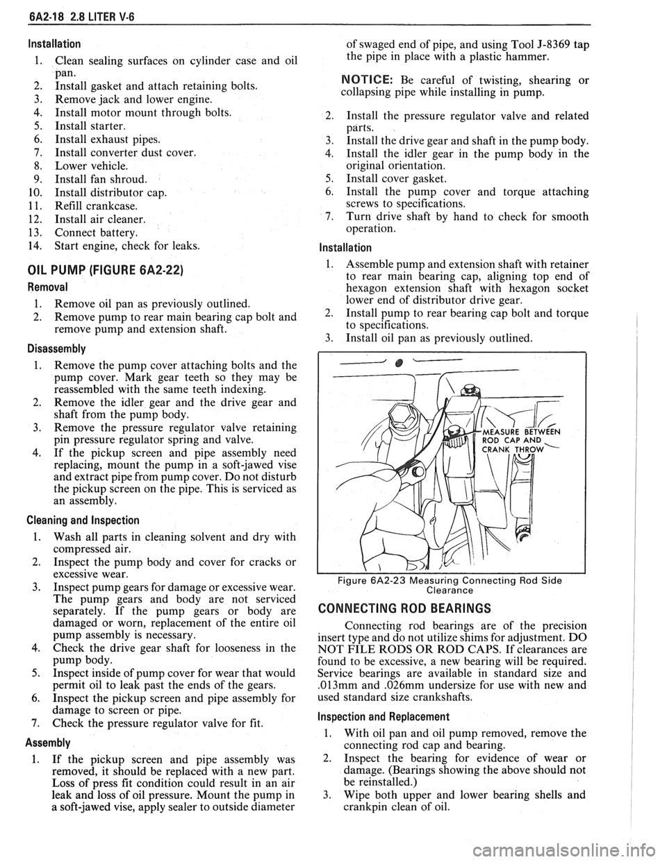
ROD CAP AND
Figure 6A2-23 Measuring Connecting Rod Side
Clearance
CONNECTING ROD BEARINGS
Connecting rod bearings are of the precision
insert type and do not utilize shims for adjustment. DO
NOT FILE RODS OR ROD CAPS. If clearances are
found to be excessive, a new bearing will be required.
Service bearings are available in standard size and
.013mm and .026mm undersize for use with new and
used standard size crankshafts.
lnspection and Replacement
1. With oil pan and oil pump removed, remove the
connecting rod cap and bearing.
2. Inspect the bearing for evidence of wear or
damage. (Bearings showing the above should not
be reinstalled.)
3. Wipe both upper and lower bearing shells and
crankpin clean of oil.
Page 381 of 1825
6A3-2 V-8 ENGINE
VALVE TRAIN
A very simple ball pivot-type train is used.
Motion is transmitted from the camshaft through the
hydraulic lifter and push rod to the rocker arm. The
rocker arm pivots on its ball and transmits the
camshaft motion to the valve. The rocker-arm ball is
retained by a nut.
HYDRAULIC VALVE LIFTERS
Hydraulic Valve Lifters are used to keep all parts
of the valve train in constant contact.
The hydraulic lifter assembly consists of: a roller,
the lifter body, which rides in the cylinder block boss,
a plunger, a push rod seat, a metering valve, a plunger
spring, a check ball and spring, a check ball retainer
and a push rod seat retainer.
When the lifter is riding on the low point of the
cam, the plunger spring keeps the plunger and push rod
seat in contact with the push rod.
When the lifter body begins to ride up the cam
lobe, the check ball cuts off the transfer of oil from the
reservoir below the plunger. The plunger and lifter
body then rise as a unit, pushing up the push rod and
opening the valve.
As the lifter body rides down the other side of the
cam, the plunger follows with it until the valve closes.
The lifter body continues to follow the cam to its low
point, but the plunger spring keeps the plunger in
contact with the push rod. The ball check valve will then
move off its seat and the lifter reservoir will
remain full.
INTAKE MANIFOLD
The intake manifold for those engines with
carburetors are made of cast iron or aluminum double
level design for efficient fuel distribution. An Exhaust
Gas Recirculation (EGR) port is also cast into the
manifold for the mixture of exhaust gases with the fuel
air mixture.
The intake manifold for those vehicles equipped
with
PFI is a cast aluminum unit. It centrally supports
a fuel rail with
8 fuel injectors.
EXHAUST MANIFOLDS
Two cast iron exhaust manifolds are used to
direct exhaust gases from the combustion chambers to
the exhaust system. The left hand side manifold
receives a heat shield that is used to route heated air
to the air cleaner. for better fuel vaporization during
warm-up.
COMBUSTION CHAMBERS
Combustion Chambers are cast to insure uniform
shape for all cylinders. Spark plugs are located between
the intake and exhaust valves. The contoured wedge
shape of the combustion chamber minimizes the
possibility of detonation, facilitates breathing and
provides swirling turbulence for smooth, complete
combustion.
ENGINE LUBRICATION
Full pressure lubrication through a full flow oil through drilled passages, to the camshaft and
filter, is furnished by a gear-type oil pump. The crankshaft to lubricate the bearings. The valve lifter oil
distributor, driven by a helical gear on the camshaft,
gallery feeds the valve lifters which, through hollow
drives the oil pump. The main oil gallery feeds oil,
push rods, feed the individually mounted rocker arms.