pcv PONTIAC FIERO 1988 Service Repair Manual
[x] Cancel search | Manufacturer: PONTIAC, Model Year: 1988, Model line: FIERO, Model: PONTIAC FIERO 1988Pages: 1825, PDF Size: 99.44 MB
Page 16 of 1825
- -
GENERAL INFORMATION OA-13
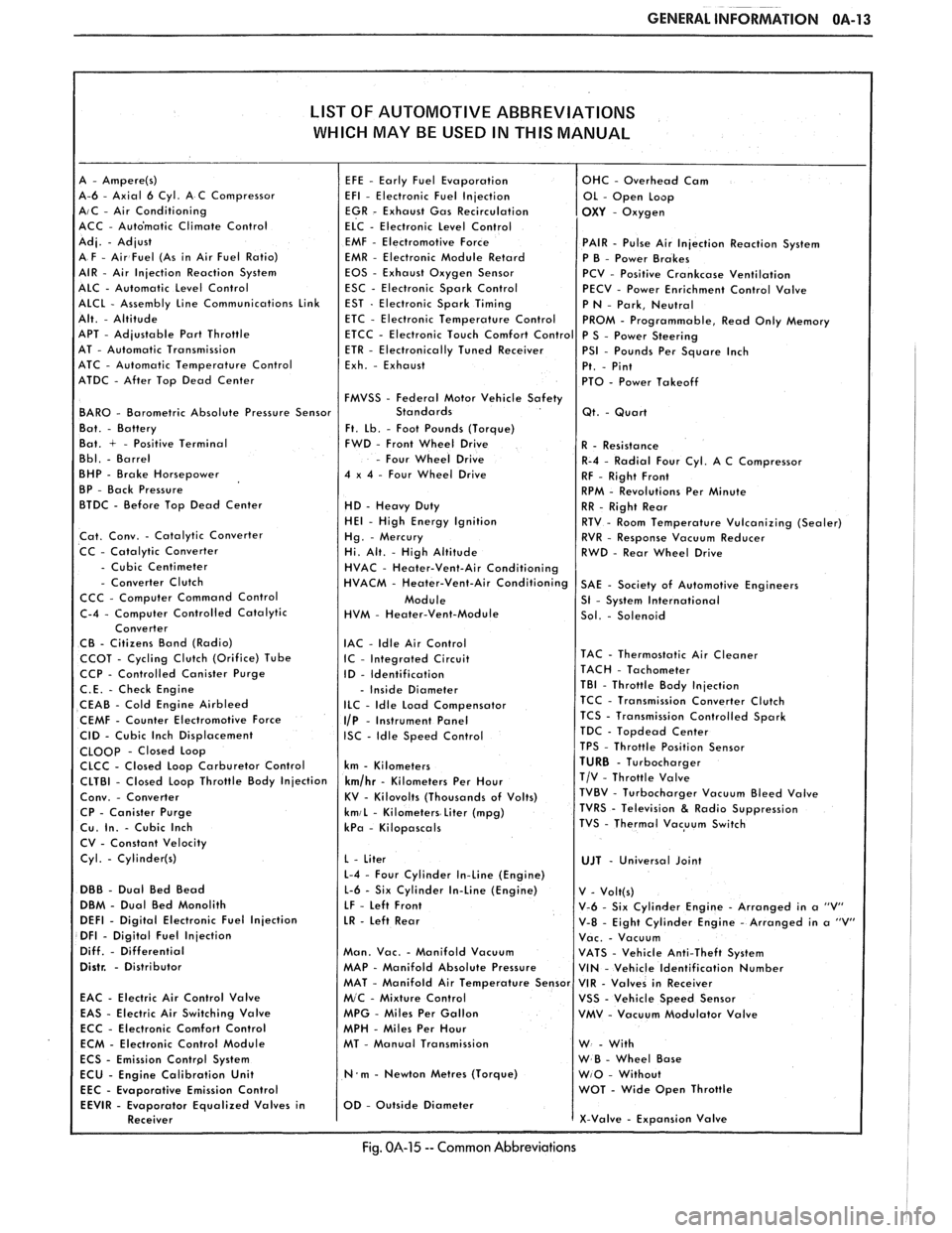
LIST OF AUTOMOTIVE ABBREVIATIONS
WHICH MAY
BE USED IN THIS MANUAL
A-6 - Axial 6 Cyl. A C Compressor AIC - Air Conditioning
ACC - Auto'matic Climate Control
EMF
- Electromotive Force PAIR - Pulse Air Injection Reaction System
EMR - Electronic Module Retard
P B - Power Brakes
EOS - Exhaust Oxygen Sensor
PCV - Positive Crankcase Ventilation
ESC - Electronic Spark Control
PECV - Power Enrichment Control Valve
APT
- Adjustable Part Throttle
AT - Automatic Transmission
ATC - Automatic Temperature Control
ATDC
- After Top Dead Center
FMVSS
- Federal Motor Vehicle Safety BAR0 - Barometric Absolute Pressure Sensor
Ft. Lb. - Foot Pounds (Torque)
Bat. + - Positive Terminal FWD - Front Wheel Drive
- Four Wheel Drive
BHP - Brake Horsepower 4 x 4 - Four Wheel Drive
BP - Back Pressure
BTDC - Before Top Dead Center
HD - Heavy Duty HE1 - High Energy Ignition
Cat. Conv. - Catalytic Converter
CC - Catalytic Converter
- Cubic Centimeter - Converter Clutch
CCC - Computer Command Control
HVM
- Heater-Vent-Module
IAC
- ldle Air Control CCOT - Cycling Clutch (Orifice) Tube IC - Integrated Circuit CCP - Controlled Canister Purge
ID - Identification
C.E. - Check Engine - Inside Diameter
CEAB - Cold Engine Airbleed ILC - Idle Load Compensator
CEMF - Counter Electromotive Force I/P - Instrument Panel
CID - Cubic Inch Displacement ISC - Idle Speed Control CLOOp - Closed Loop
CLCC - Closed Loop Carburetor Control km - Kilometers
CP
- Canister Purge kmiL - Kilometers Liter (mpg) Cu. In. - Cubic Inch kPa - Kilopascals
CV - Constant Velocity
Cyl.
- Cylinder(s)
L-4 - Four Cylinder In-Line (Engine)
DBB - Dual Bed Bead L-6 - Six Cylinder In-Line (Engine)
DBM - Dual Bed Monolith
LF - Left Front DEFl - Digital Electronic Fuel Injection LR - Left Rear DFI - Digital Fuel Injection
Diff. - Differential Man. Vac. - Manifold Vacuum Distr. - Distributor MAP - Manifold Absolute Pressure
EAC
- Electric Air Control Valve
EAS - Electric Air Switching Valve MPG - Miles Per Gallon
ECC - Electronic Comfort Control
MPH - Miles Per Hour
ECM - Electronic Control Module MT - Manual Transmission
N.m - Newton Metres (Torque)
Emission Control
Fig. 014-15 -- Common Abbreviations
Page 20 of 1825
F CARLINE
ITEM 10
TransmissionRransaxle Service
The manual transmission or transaxle fluid does not
require changing. (Corvette only.) Change fluid in over-
drive unit every 30,000 miles (50 000 km).
For automatic transmissions or transaxles, change
both the fluid and filter every 15,000 miles (25 000 km) if
the car is mainly driven under one or more of these
conditions:
@ In heavy city traffic where the outside temperature
regularly reaches 90°F (32°C) or higher.
@ In hilly or mountainous terrain.
@ Frequent trailer pulling.
@ Uses such as found in taxi, police car or delivery
service.
If you do not use your car under any of these condi-
tions, change both the fluid and filter every 100,000 miles
(160 000 km). See you Owner's Manual for further
details.
ITEM 11
Spark Plug Service*
Replace spark plugs with type listed in your Owner's
Manual.
ITEM 12
Spark Plug Wire Inspection*
Clean wires and inspect for burns, cracks or other dam-
age. Check the wire boot fit at distributor and at spark plugs.
Replace wires as needed.
ITEM 13
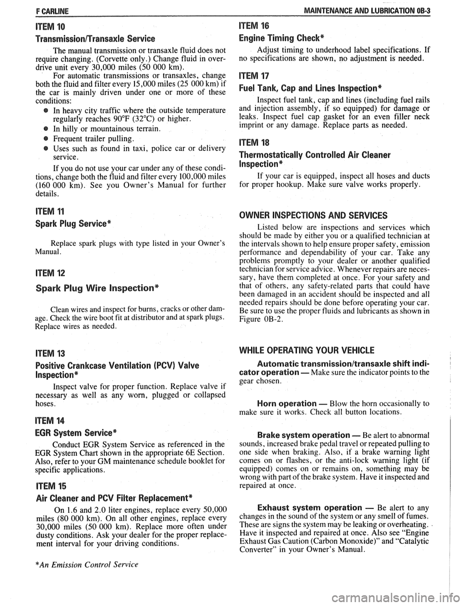
Positive Crankcase Ventilation (PCV) Valve
Inspection*
Inspect valve for proper function. Replace valve if
necessary as well as any worn, plugged or collapsed
hoses.
ITEM 14
EGR System Service*
Conduct EGR System Service as referenced in the
EGR System Chart shown in the appropriate 6E Section.
Also, refer to your GM maintenance schedule booklet for
specific applications.
ITEM 15
Air Cleaner and PCV Filter Replacement*
On 1.6 and 2.0 liter engines, replace every 50,000
miles (80 000 km). On all other engines, replace every
30,000 miles (50 000 km). Replace more often under
dusty conditions. Ask your dealer for the proper replace-
ment interval for your driving conditions.
MAINTENANCE AND LUBRICATION 08-3
ITEM 16
Engine Timing Check*
Adjust timing to underhood label specifications. If
no specifications are shown, no adjustment is needed.
ITEM 17
Fuel Tank, Cap and Lines Inspection*
Inspect fuel tank, cap and lines (including fuel rails
and injection assembly, if so equipped) for damage or
leaks. Inspect fuel cap gasket for an even filler neck
imprint or any damage. Replace parts as needed.
ITEM 18
Thermostatically Controlled Air Cleaner
Inspection*
If your car is equipped, inspect all hoses and ducts
for proper hookup. Make sure valve works properly.
OWNER INSPECTIONS AND SERVICES
Listed below are inspections and services which
should be made by either you or a qualified technician at
the intervals shown to help ensure proper safety, emission
performance and dependability of your car. Take any
problems promptly to your dealer or another qualified
technician for service advice. Whenever repairs are neces-
sary, have them completed at once. For your safety and
that of others, any safety-related parts that could have
been damaged in an accident should be inspected and all
needed repairs should be done before operating your car.
Be sure to use the proper fluids and lubricants as shown in
Figure OB-2.
WHILE OPERATING YOUR VEHICLE
Automatic transmissionltransaxle shift indi-
cator operation - Make sure the indicator points to the
gear chosen.
Horn operation - Blow the horn occasionally to
make sure it works. Check all button locations.
I
Brake system operation -- Be alert to abnormal
sounds, increased brake pedal travel or repeated pulling to
one side when braking. Also, if a brake warning light
comes on or flashes, or the anti-lock warning light (if
equipped) comes on or remains on, something may be
wrong with part of the brake system. Have it inspected and
repaired at once.
Exhaust system operation - Be alert to any
changes in the sound of the system or any smell of fumes.
These are signs the system may be leaking or overheating.
.
Have it inspected and repaired at once. Also see "Engine
Exhaust Gas Caution (Carbon Monoxide)" and "Catalytic
Converter" in your Owner's Manual.
*An Emission Control Service
Page 348 of 1825
ENGINE GENERAL INFORMATION 6-3
B, Section 6E2 - Fuel Injection (TBI)
B, Section 6E3 - Fuel Injection (Ported)
ENGINE MECHANICAL DIAGNOSIS
The following diagnostic information covers common problems and possible causes. When
the proper diagnosis is made, the problem should be corrected by adjustment, repair or part
replacement as required. Refer to the appropriate section of the manual for these procedures.
EXCESSIVE OIL LOSS
B, External oil leaks. Tighten bolts and/or replace o Continuous high speed driving, and/or severe
gaskets and seals as necessary. usage
such as trailer hauling, will normally cause
decreased oil mileage.
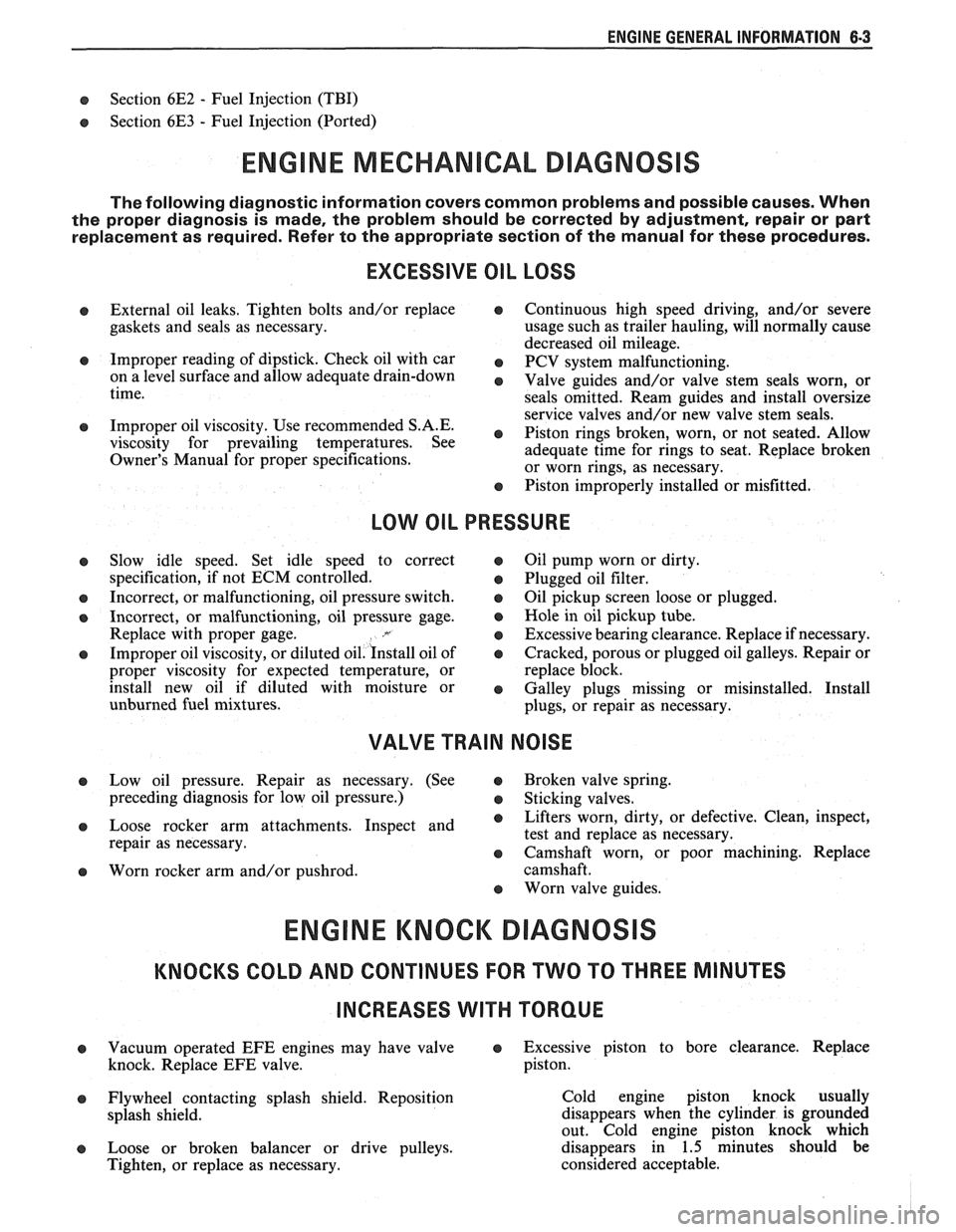
e Improper reading of dipstick. Check oil with car PCV system malfunctioning. on a level surface and allow adequate drain-down Valve guides and/or valve stem seals worn, or time.
seals omitted. Ream guides and install oversize
service valves and/or new valve stem seals.
Improper Use S.A'E' Piston rings broken, worn, or not seateded. Allow viscosity for prevailing temperatures. See
adequate time for rings to seat. Replace broken
Owner's Manual for proper specifications.
or worn rings, as necessary.
Piston improperly installed or misfitted.
LOW OIL PRESSURE
Slow idle speed. Set idle speed to correct
specification, if not ECM controlled.
Incorrect, or malfunctioning, oil pressure switch.
Incorrect, or malfunctioning, oil pressure gage.
Replace with proper gage.
.*
Improper oil viscosity, or diluted oil. install oil of
proper viscosity for expected temperature, or
install new oil if diluted with moisture or
unburned fuel mixtures.
o Oil pump worn or dirty.
e Plugged oil filter.
e Oil pickup screen loose or plugged.
B, Hole in oil pickup tube.
e Excessive bearing clearance. Replace if necessary.
o Cracked, porous or plugged oil galleys. Repair or
replace block.
o Galley plugs missing or misinstalled. Install
plugs, or repair as necessary.
VALVE TRAIN NOISE
e Low oil pressure. Repair as necessary. (See o Broken valve spring.
preceding diagnosis for low oil pressure.)
o Sticking valves.
o Loose rocker arm attachments. Inspect and B, Lifters worn, dirty, or defective. Clean, inspect,
test and replace as necessary.
repair as necessary.
o Camshaft worn, or poor machining. Replace
o Worn rocker arm and/or pushrod. camshaft.
B, Worn valve guides.
ENGINE KNOCK DIAGNOSIS
KNOCKS COLD AND CONTINUES FOR TWO TO THREE MINUTES
INCREASES
WITH TORQUE
o Vacuum operated EFE engines may have valve o Excessive piston to bore clearance. Replace
knock. Replace EFE valve. piston.
e Flywheel contacting splash shield. Reposition
splash shield.
e Loose or broken balancer or drive pulleys.
Tighten, or replace as necessary. Cold engine piston knock usually
disappears when the cylinder is grounded
out. Cold engine piston knock which
disappears in 1.5 minutes should be
considered acceptable.
Page 387 of 1825
6A3-8 V-8 ENGINE
10. Remove exhaust pipe nuts.
1 1. Lower vehicle.
12. Remove manifold bolts.
13. Remove manifold.
Installation
1. Clean mating surfaces on manifold and head,
then install manifold in position and install bolts
finger tight.
2. Torque bolts to specifications.
3. Reverse removal procedures.
4. Adjust necessary drive belts.
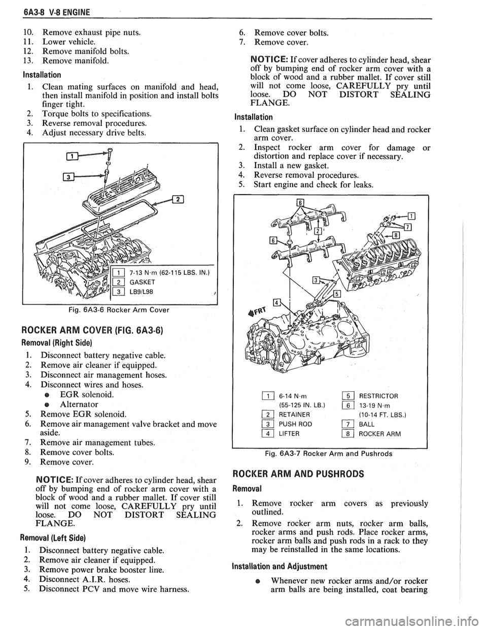
P
IN.)
Fig. 6A3-6 Rocker Arm Cover
ROCKER ARM COVER (FIG. 6A3-6)
Removal (Right Side)
1. Disconnect battery negative cable.
2. Remove air cleaner if equipped.
3. Disconnect air management hoses.
4. Disconnect wires and hoses.
EGR solenoid.
e Alternator
5. Remove EGR solenoid.
6. Remove air management valve bracket and move
aside.
7. Remove air management tubes.
8. Remove cover bolts.
9. Remove cover.
N OTI G E: If cover adheres to cylinder head, shear
off by bumping end of rocker arm cover with a
block of wood and a rubber mallet. If cover still
will not come loose, CAREFULLY pry until
loose. DO NOT DISTORT SEALING
FLANGE.
Removal (Left Side)
1. Disconnect battery negative cable.
2. Remove air cleaner if equipped.
3. Remove Power brake booster line.
4. isc connect A.I.R. hoses.
5. Disconnect PCV and move wire harness.
6. Remove cover bolts.
7. Remove cover.
NOTICE: If cover adheres to cylinder head, shear
off by bumping end of rocker arm cover with a
block of wood and a rubber mallet. If cover still
will not come loose, CAREFULLY pry until
loose. DO NOT DISTORT SEALING
FLANGE.
lnstallation
1. Clean gasket surface on cylinder head and rocker
arm cover.
2. Inspect rocker arm cover for damage or
distortion and replace cover if necessary.
3. Install a new gasket.
4. Reverse removal procedures.
5. Start engine and check for leaks.
6-14 N.m RESTRICTOR
(55-125 IN.
LB.) 161 13-19 N,rn - 1 RETAINER (10-14 FT. LBS.)
/ PUSH ROD a BALL
a LIFTER 1 ROCKER ARM
Fig. 6A3-7 Rocker Arm and Pushrods
ROCKER ARM AND PUSHRODS
Removal
1. Remove rocker arm covers as previously
outlined.
2. Remove rocker arm nuts, rocker arm balls,
rocker arms and push rods. Place rocker arms,
rocker arm balls and push rods in a rack to they
may be reinstalled in the same locations.
Installation and Adjustment
e Whenever new rocker arms and/or rocker
arm balls are being installed, coat bearing
Page 489 of 1825
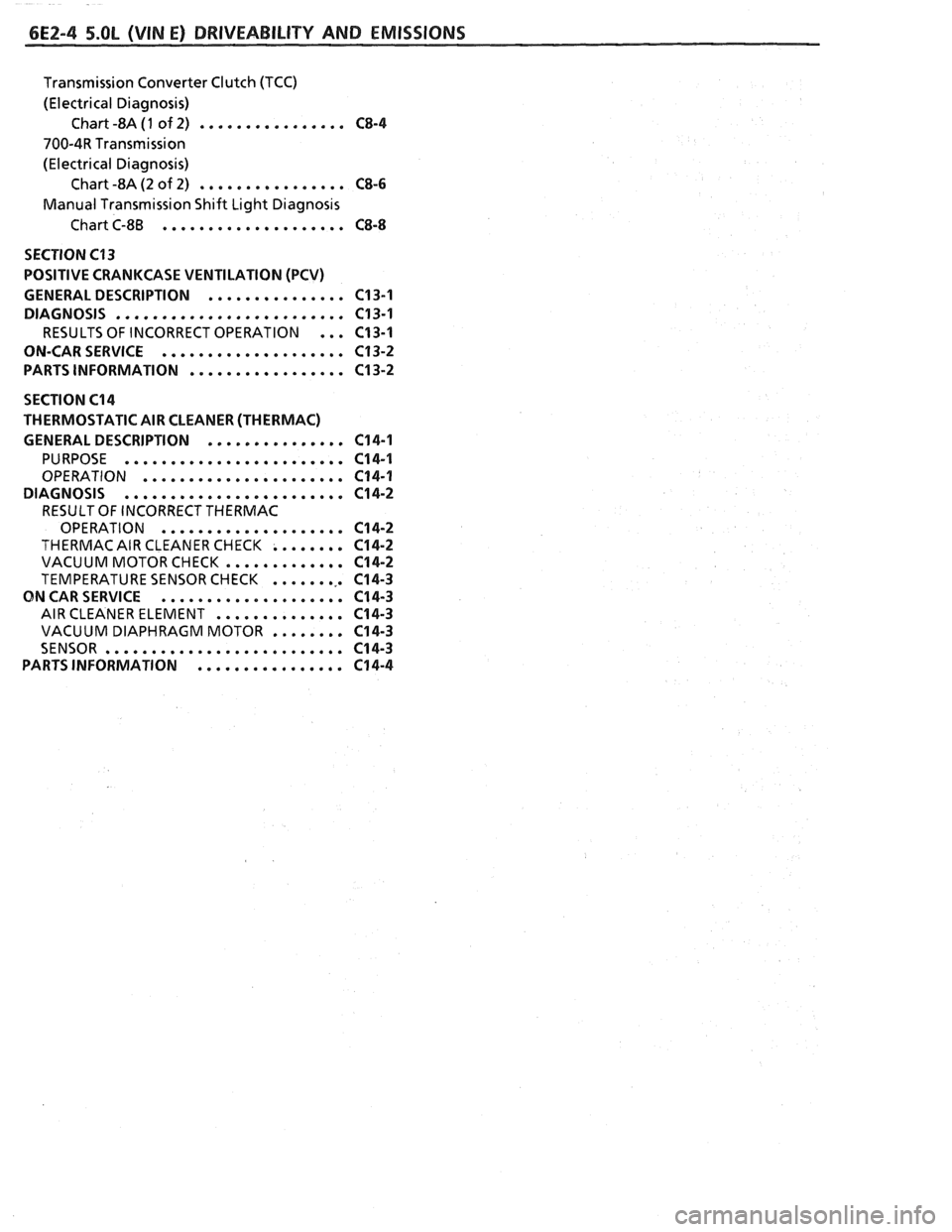
6E2-4 5.OL (VIN E) DRIVEABILITY AND EMISSIONS
Transmission Converter Clutch (TCC)
(Electrical Diagnosis) Chart -8A
(1 of 2) ................ C8-4
700-4R Transmission
(Electrical Diagnosis) Chart -8A (2 of 2)
................ CS-6
Manual Transmission Shift Light Diagnosis
Chart C-8B
.................... CS-8
SECTION C13
POSITIVE CRANKCASE VENTILATION (PCV)
GENERAL DESCRIPTION
............... C13-1
DIAGNOSIS
......................... C13-1
RESULTS OF INCORRECT OPERATION ... C13-1
ON-CARSERVICE
.................... C13-2
PARTS INFORMATION
................. C13-2
SECTION C14
THERMOSTATIC AIR CLEANER (THERMAC)
GENERAL DESCRIPTION
............... 614-1
PURPOSE ........................ C14-1
OPERATION ...................... C14-1
DIAGNOSIS
........................ C14-2
RESULT OF INCORRECT THERMAC
OPERATION
.................... C14-2
THERMAC AIR CLEANER CHECK ........ C14-2
VACUUM MOTORCHECK ............. C14-2
TEMPERATURE SENSOR CHECK ......... C14-3
ON CAR SERVICE .................... C14-3
AIR CLEANER ELEMENT .............. C14-3
VACUUM DIAPHRAGM MOTOR ........ C14-3
SENSOR .......................... C14-3
PARTSINFORMATION ................ C14-4
Page 493 of 1825
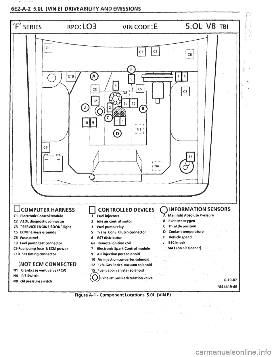
6E2-A-2 5.OL (VIN E) DRIVEABILIW AND EMISSIONS
IFf SERIES VIN CODE: E
OCOMPUTER HARNESS
C1 Electronic Control Module
C2 ALDL diagnostic connector
C3 "SERVICE ENGINE SOON" light
C5 ECM harness grounds
C6 Fuse panel
C8 Fuel pump test connector
C9 Fuel pump fuse & ECM power
C10 Set timing connector
....,
: . ... 'NOT ECM CONNECTED
N1 Crankcase vent valve (PCV)
N4 PIS Switch
N8 Oil pressure switch
[7 CONTROLLED DEVICES 0 INFORMATION SENSORS
1 Fuel injectors A Manifold Absolute Pressure
2 Idle air control motor B Exhaust oxygen
3 Fuel pump relay
C Throttle position
5 Trans. Conv. Clutch connector
D Coolant temperature
6 EST distributor
F Vehicle speed
6a Remote ignition coil
J ESCknock
7 Electronic Spark Control module MAT (on air cleaner)
9 Air injection port solenoid
10 Air injection converter solenoid
12 Exh. Gas Recirc. vacuum solenoid
15 Fuel vapor canister solenoid
Exhaust Gas Recirculation valve
6-1
0-87
Figure A-I - Component Locations 5.OL (VIN E)
Page 553 of 1825
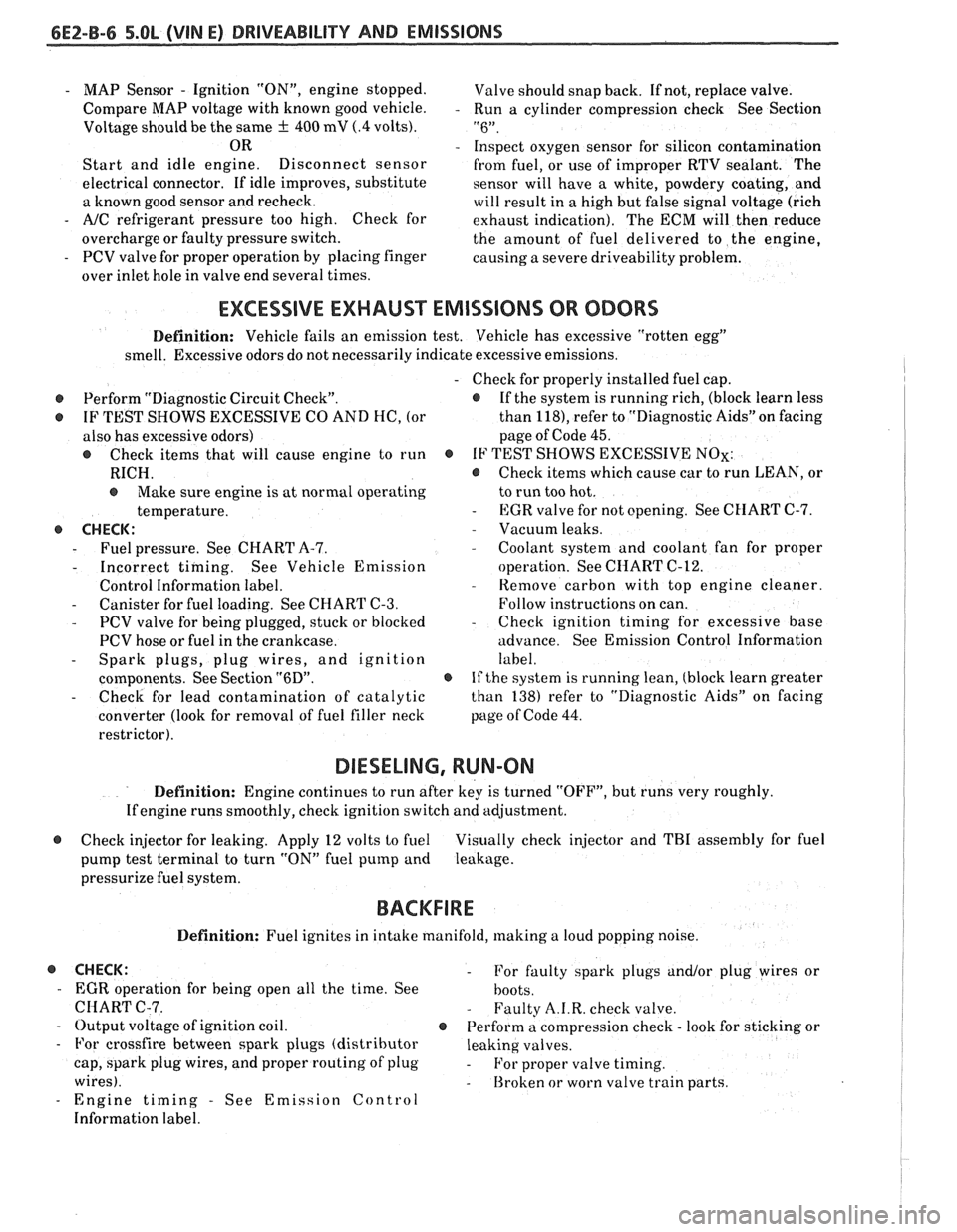
6E2-8-6 5.OL (VIN E) DRIVEABILITY AND EMISSIONS
- MAP Sensor - Ignition "ON", engine stopped.
Compare MAP voltage with known good vehicle.
-
Voltage should be the same + 400 mV (.4 volts).
OR
Start and idle engine. Disconnect
sensor
electrical connector. If idle improves, substitute
a known good sensor and recheck.
- A/C refrigerant pressure too high. Check for
overcharge or faulty pressure switch.
- PCV valve for proper operation by placing finger
over inlet hole in valve end several times. Valve
should snap back. If not, replace valve.
Run a cylinder compression check See Section
" 6".
Inspect oxygen sensor for silicon contamination
from fuel, or use of improper RTV sealant. The
sensor will have a white, powdery coating, and
will result in a high but false signal voltage (rich
exhaust indication). The ECM will then reduce
the amount of fuel delivered to the engine,
causing a severe driveability problem.
EXCESSIVE EXHAUST EMISSIONS OR ODORS
Definition: Vehicle fails an emission test. Vehicle has excessive "rotten egg"
smell. Excessive odors do not necessarily indicate excessive emissions.
@ Perform "Diagnostic Circuit Check".
@ IF TEST SHOWS EXCESSIVE CO AND HC, (or
also has excessive odors)
@ Check items that will cause engine to run
RICH.
e Make sure engine is at normal operating
temperature.
o CHECK:
- Fuel pressure. See CHART A-7.
- Incorrect timing. See Vehicle Emission
Control Information label.
- Canister for fuel loading. See CHART C-3.
- PCV valve for being plugged, stuck or blocked
PCV hose or fuel in the crankcase.
- Spark plugs, plug wires, and ignition
components. See Section
"6D".
- Check for lead contamination of catalytic
converter (look for removal of fuel filler neck
restrictor).
- Check for properly installed fuel cap.
@ If the system is running rich, (block learn less
than
1181, refer to "Diagnostic Aids" on facing
page of Code
45.
o IF TEST SHOWS EXCESSIVE NOx:
@ Check items which cause car to run LEAN, or
to run too hot.
- EGR valve for not opening. See CHART C-7.
- Vacuum leaks. - Coolant system and coolant fan for proper
operation. See
CHART C-12.
- Remove carbon with top engine cleaner.
Follow instructions on can.
- Check ignition timing for excessive base
advance. See Emission Control Information
label.
@ If the system is running lean, (block learn greater
than
138) refer to "Diagnostic Aids" on facing
page of Code
44.
DIESELING, RUN-ON
Definition: Engine continues to run after key is turned "OFF", but runs very roughly.
Ifengine runs smoothly, check ignition switch and adjustment.
@ Check injector for leaking. Apply 12 volts to fuel Visually check injector and TBI assembly for fuel
pump test terminal to turn "ON" fuel pump and leakage.
pressurize fuel system.
BACKFIRE
Definition: Fuel ignites in intake manifold, making a loud popping noise.
@ CHECK: - For faulty spark plugs and/or plug wires or
- EGR operation for being open all the time. See
hoots.
CHART C-7. - Faulty A.I.R. check valve.
- Output voltage of ignition coil. @ Perform a compression check - look for sticking or
- For crossfire between spark plugs (distributor leaking valves.
cap, spark plug wires, and proper routing' of plug
- For proper valve timing.
wires).
- Broken or worn valve train parts.
- Engine timing - See Emission Control
Information label.
Page 555 of 1825
6EZ-C-1 5.OL (VIN E) DRIVEABILITY AND EMISSIONS
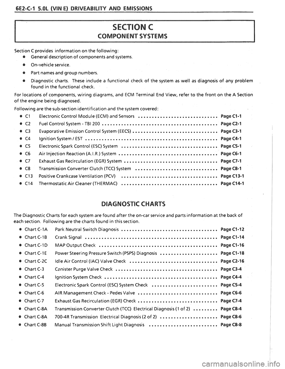
Section C provides information on the following:
@ General description of components and systems.
@ On-vehicle service.
@ Part names and group numbers.
@ Diagnostic charts. These include a functional check of the system as well as diagnosis of any problem
found in the functional check.
For locations of components, wiring diagrams, and ECM Terminal End View, refer to the front on the A Section
of the engine being diagnosed.
Following are the sub-section identification and the system covered:
@ C1 Electronic Control Module (ECM) and Sensors ............................. Page C1-1
@ C2 Fuel Control System - TBI 200 .......................................... Page C2-1
Evaporative Emission Control System (EECS) ...............................
Ignition System 1 EST ................................................
Electronic Spark Control (ESC) System ...................................
Air Injection Reaction (A.I.R.) System ....................................
Exhaust Gas Recirculation (EGR) System ..................................
Transmission Converter Clutch (TCC) System ..............................
Positive Crankcase Ventilation (PCV) ...................................
Thermostatic Air Cleaner (THERMAC) ...................................
BIAGNOSIIC CHARTS
Page C3-1
Page C4-1
Page C5-1
Page C6-1
Page C7-1
Page C8-1
Page C13-1
Page C14-1
The Diagnostic Charts for each system are found after the on-car service and parts information at the back of
each section. Following are the charts found in this section.
@ Chart C-1A Park Neutral Switch Diagnosis ................................... Page C1-12
@ Chart C-1B Crank Signal ................................................ Page C1-14
@ Chart C-1 D MAP Output Check ........................................ Page C1-16 I
..................... @ Chart C-1 E Power Steering Pressure Switch (PSPS) Diagnosis Page C1-18 1
................................ @ Chart C-2C Idle Air Control (IAC) Valve Check Page C2-16 !
..................................... @ Chart C-3 Canister Purge Valve Check Page C3-4 I
@ Chart C-4 Ignition System Check ......................................... Page C4-4
........................ @ Chart C-5 Electronic Spark Control (ESC) System Check Page C5-4
- ............................. @ Chart C-6 AIR Management Check Pedes Valve Page C6-6
............................. Chart C-7 Exhaust Gas Recirculation (EGR) Check Page C7-4
@ Chart C-8A Transmission Converter Clutch (TCC) Electrical Diagnosis (1 of 2) ......... Page C8-4 I
@ Chart C-8A 700-4R Transmission Electrical Diagnosis (2 of 2) ..................... Page C8-6 I
......................... @ Chart C-8B Manual Transmission Shift Light Diagnosis Page C8-8
Page 636 of 1825
DRIVEABILITY AND EMISSIONS - 5.OL (VIN E) 6E2-CI 3-1 --
SECTION C13
POSI"BVE CRANKCASE VENTILATION (PCV)
CONTENTS
GENERAL DESCRIPTION ............*.. C13-1 ON-CARSERVICE .................... C13-2
DIAGNOSIS
.*.....................* C13-1 PARTSINFORMATION...,............. C13-2
RESULTS OF INCORRECT OPERATION ... C13-1
GENERAL DESCRIPTION
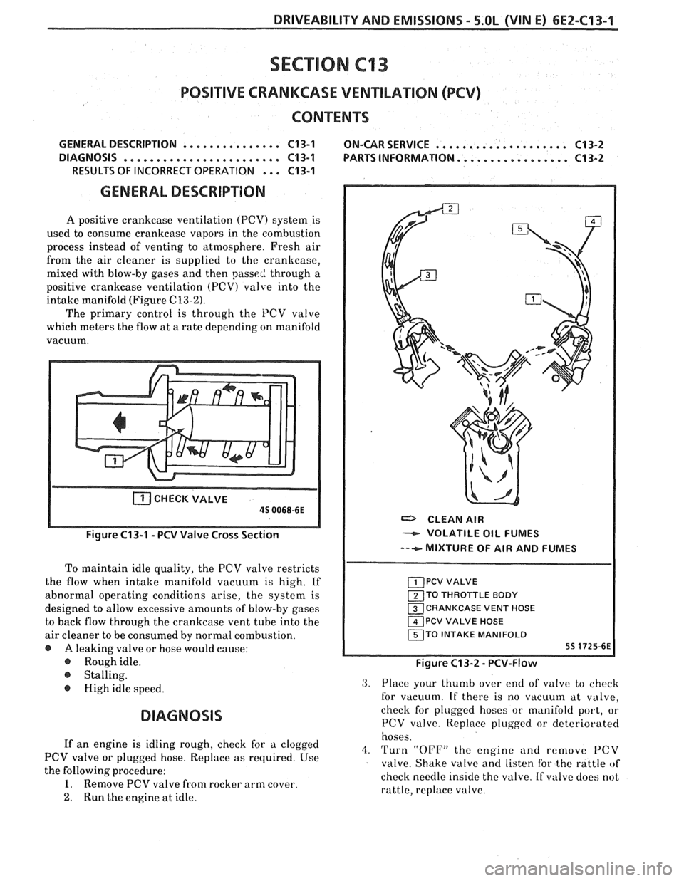
A positive crankcase ventilation (PCV) system is
used to consume crankcase vapors in the combustion
process instead of venting to atmosphere. Fresh air
from the air cleaner is supplied to the crankcase,
mixed with blow-by gases and then
passe2 through a
positive crankcase ventilation
(PCV) valve into the
intake manifold (Figure
C13-2).
The primary control is through the PCV valve
which meters the flow at a rate depending on manifold
vacuum.
CHECKVALVE
a CLEAN AIR
- VOLATILE OIL FUMES
--+ MIXTURE OF AIR AND FUMES
To maintain idle quality, the PCV valve restricts
the flow when intake manifold vacuum is high. If
abnormal operating conditions arise, the system is
TO THROTTLE BODY
designed to allow excessive amounts of blow-by gases CRANKCASE VENT HOSE
to back flow through the crankcase vent tube into the PCV VALVE HOSE
air cleaner to be consumed by normal combustion. TO INTAKE MANIFOLD
@ A leaking valve or hose would cause:
@ Roughidle. Figure C13-2 - PCV-Flow
@ Stalling.
@ High idle speed.
DIAGNOSIS
3. Place your thumb over end of valve to check
for vacuum. If there is no
vacuuin at valve,
check for plugged hoses or manifold port, or
PCV valve. Iteplace plugged or deteriorated
hoses.
If an engine is idling rough, check for a clogged
4. Turn "OFF" the engine and remove PCV PCV valve or plugged hose. Replace as required. Use
valve. Shake valve and listen for the rattle of
the following procedure:
check needle inside the valve. If
valve does not 1. Remove PCV valve from rocker arm cover.
rattle, replace valve.
2. Run the engine at idle.
Page 637 of 1825
6E2-C"1-2 DRIVEABILITY AND EMISSIONS - 5.OL (VIN E)
With this system, any blow-by in excess of the
system capacity (from a badly-worn engine, sustained
heavy load,
etc.) is exhausted into the air cleaner and
is drawn into the engine.
Proper operation of the PCV System is dependent
upon a sealed engine. If oil sludging or dilution is
noted, and the PCV System is functioning properly,
check engine for possible cause and correct to ensure
that system will function as intended.
Results of Incorrect PCV Operation
@ A plugged valve or hose may cause:
@ Rough idle.
@ Stalling or slow idle speed.
Oil leaks.
@ Oil in air clcaner.
@ Sludge in engine.
ON-CAR SERVICE
An engine which is operated without any
crankcase ventilation can be damaged. Therefore, it is
important to replace the
PCV valve and air cleaner
breather at intervals shown in Section
"OB".
Periodically, inspect the hoses and clamps and
replace any showing signs of deterioration.
PARTS INFORMATION
PART NAME GROUP
Air Cleaner ......................... 3.402
................ Valve Asm, UCase Vent 1.745