washer fluid PONTIAC FIERO 1988 Service Repair Manual
[x] Cancel search | Manufacturer: PONTIAC, Model Year: 1988, Model line: FIERO, Model: PONTIAC FIERO 1988Pages: 1825, PDF Size: 99.44 MB
Page 21 of 1825
OB-4 MAINTENANCE AND LUBRICATION
Tire and wheel operation - Be alert to a vibra-
tion of the steering wheel or seat at normal highway
speeds. This may mean a wheel balance is needed. Also, a
pull right or left on a straight, level road may show the
need for
a tire pressure adjustment or wheel alignment.
Steering system operation - Be alert to
changes in steering action. An inspection is needed when
the steering wheel is harder to turn or has too much free
play or if unusual sounds are noted when turning or
parking.
Headlight aim operation - Take note of light
pattern occasionally. If beam aim doesn't look right,
headlights should be adjusted.
AT EACH FUEL FILL
Engine oil level check - Check engine oil level
and add if necessary. See your Owner's
Manual for further
details.
NOTICE: A large loss in this system may indicate a
problem. Have it inspected and repaired at once.
Engine coolant level and condition - Check
engine coolant level in coolant reservoir tank and add if
necessary. Replace if dirty or rusty. See your Owner's
Manual for further details.
NOTICE: A large loss in this system may indicate a
problem. Have it inspected and repaired at once.
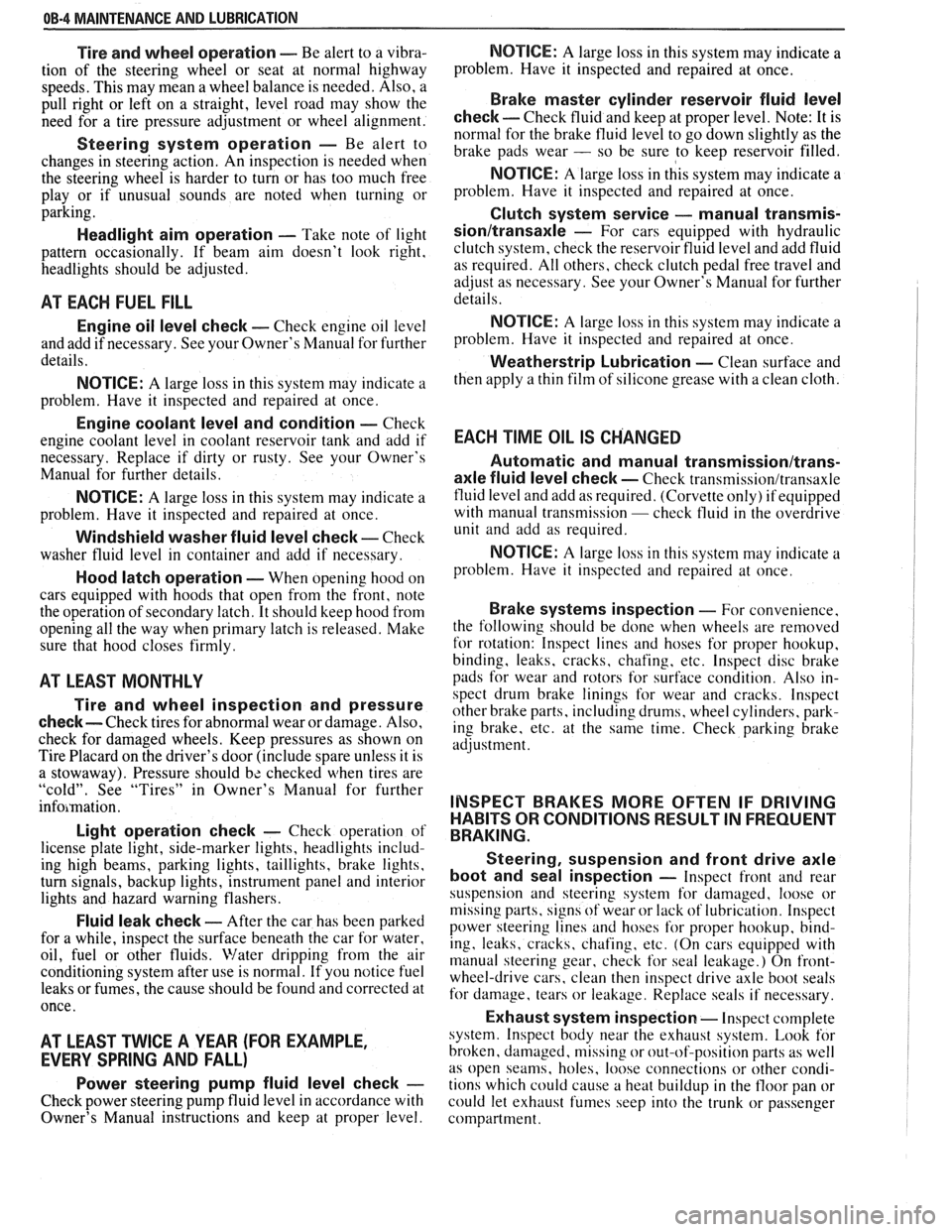
Windshield washer fluid level check -- Check
washer fluid level in container and add if necessary.
Hood latch operation - When opening hood on
cars equipped with hoods that open from the front, note
the operation of secondary latch. It should keep hood from
opening all the way when primary latch is released. Make
sure that hood closes firmly.
AT LEAST MONTI-ILY
Tire and wheel inspection and pressure
check--
Check tires for abnormal wear or damage. Also,
check for damaged wheels. Keep pressures as shown on
Tire Placard on the driver's door (include spare unless it is
a stowaway). Pressure should b\: checked when tires are
"cold". See "Tires" in Owner's Manual for further
infomation.
Light operation check - Check operation of
license plate light, side-marker lights, headlights includ-
ing high beams, parking lights, taillights, brake lights.
turn signals, backup lights, instrument panel and interior
lights and hazard warning flashers.
Fluid leak check - After the car has been parked
for a while, inspect the surface beneath the car for water,
oil, fuel or other fluids. Water dripping from the air
conditioning system after use is normal. If you notice fuel
leaks or fumes, the cause should be found and corrected at
once.
AT LEAST TWICE A YEAR (FOR EXAMPLE,
EVERY SPRING AND FALL)
Power steering pump fluid level check --
Check power steering pump fluid level in accordance with
Owner's Manual instructions and keep at proper level.
NOTICE: A large loss in this system may indicate a
problem. Have it inspected and repaired at once.
Brake master cylinder reservoir fluid level
check ---- Check fluid and keep at proper level. Note: It is
normal for the brake fluid level to go down slightly as the
brake pads wear
- so be sure to keep reservoir filled.
NOTICE: A large loss in this system may indicate a
problem. Have
it inspected and repaired at once.
Clutch system service --- manual transmis-
sionltransaxle --- For cars equipped with hydraulic
clutch system, check the reservoir fluid level and add fluid
as required. All others, check clutch pedal free travel and
adjust as necessary. See your Owner's Manual for further
details.
~
NOTICE: A large loss in this system may indicate a
problem. Have it inspected and repaired at once.
Weatherstrip Lubrication - Clean surface and
then apply a thin film of silicone grease with a clean cloth.
EACH TIME OIL IS CHANGED
Automatic and manual transmissionltrans-
axle fluid level check - Check transmission/transaxle
fluid level and add as required. (Corvette only) if equipped
with manual transmission
- check fluid in the overdrive
unit and add as required.
NOTICE: A large loss in this system may indicate a
problem. Have
it inspected and repaired at once.
Brake systems inspection - For convenience,
the following should be done when wheels are removed
for rotation: Inspect lines and hoses for proper hookup,
binding, leaks, cracks, chafing, etc. Inspect disc brake
pads for wear and rotors for surface condition. Also in-
spect drum brake linings for wear and cracks. Inspect
other brake parts, including drums, wheel cylinders, park-
ing brake, etc. at the same time. Check parking brake
adjustment.
INSPECT BRAKES MORE OFTEN IF DRIVING
HABITS OR CONDITIONS RESULT IN FREQUENT
BRAKING.
Steering, suspension and front drive axle
boot and seal inspection
- Inspect front and rear
suspension and steering system for damaged, loose or
missing parts, signs of wear or lack of lubrication. Inspect
power steering lines and hoses for proper hookup, bind-
ing, leaks, cracks, chafing, etc. (On cars equipped with
manual steering gear, check for seal leakage.) On
front-
wheel-drive cars, clean then inspect drive axle boot seals
for damage, tears or leakage. Replace seals if necessary.
Exhaust system inspection - Inspect complete
system. Inspect body near the exhaust system. Look for
broken, damaged, missing or out-of-position parts as well
as open seams, holes, loose connections or other condi-
tions which could cause a heat buildup in the tloor pan or
could let exhaust fumes seep into the trunk or passenger
compartment.
Page 23 of 1825
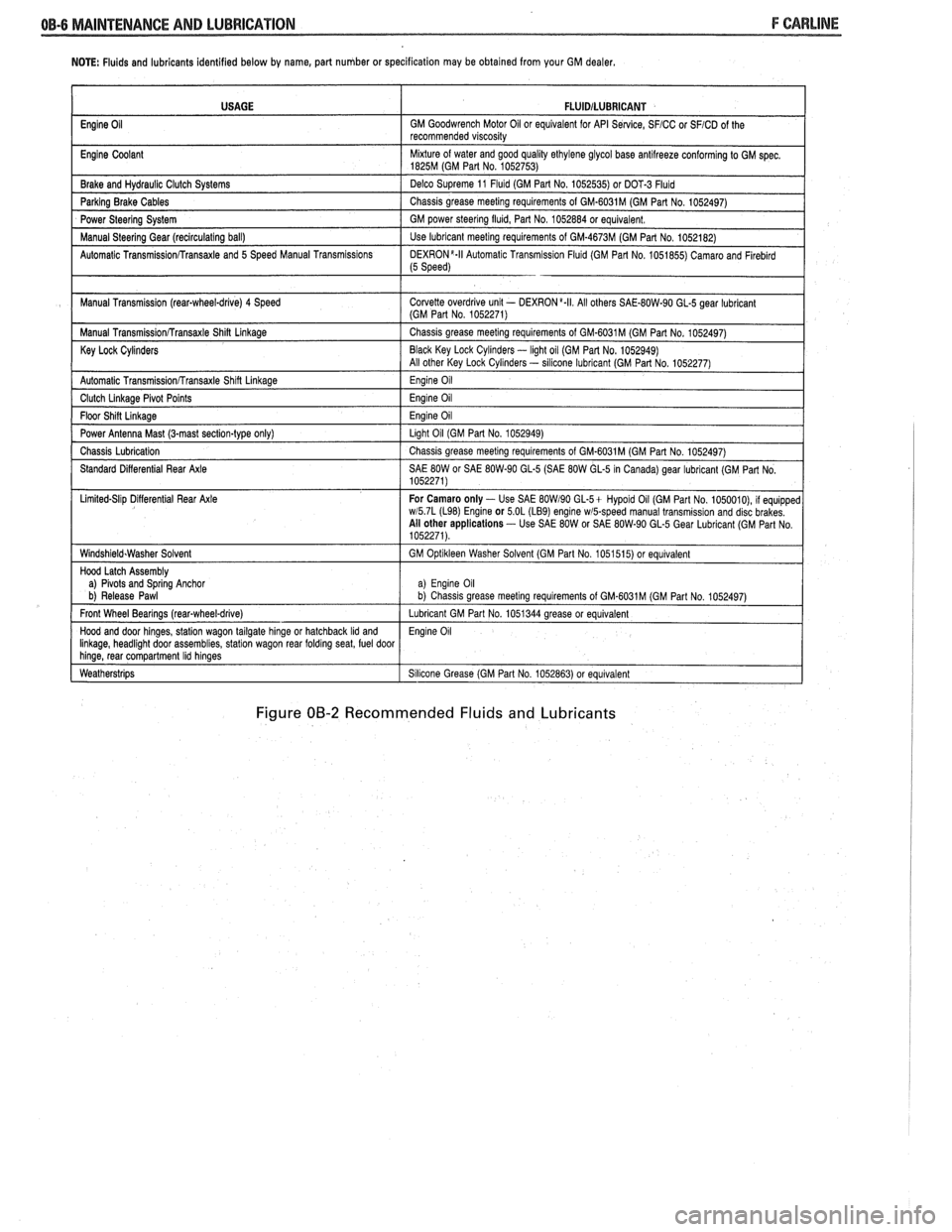
NOTE: Fluids and lubricants identified below by name, part number or specification may be obtained from your GM dealer.
Figure 00-2 Recommended Fluids and Lubricants
USAGE
Engine
Oil
Engine Coolant
Brake and
Hydraul~c Clutch Systems
Parking Brake Cables
Power Steering System
Manual
Steerlng Gear (reclrculat~ng ball)
Automatic
Transrn~ssionRransaxle and 5 Speed Manual Transm~ss~ons
Manual Transm~ssion (rear-wheel-drive) 4 Speed
Manual
Transm~ss~onRransaxle Shin Linkage
Key Lock Cylinders
Automatic Transmlss~onfrransaxle Shlft Llnkage
Clutch Llnkage Plvot Po~nts
Floor Sh~n L~nkage
Power Antenna Mast (3-mast sect~on-type only)
Chass~s Lubr~cation
Standard D~fferent~al Rear Axle
L~m~ted-Sl~p D~flerent~al Rear Axle
W~ndsh~eld.Washer Solvent
Hood Latch Assembly
a)
Plvots and Sprlng Anchor
b) Release Pawl
Front Wheel Bearings
(rearqwheel-drive)
Hood and door hlnges, statlon wagon tailgate hlnge or hatchback Ild and Ilnkage, headl~ght door assembl~es, statlon wagon rear foldrng seat, fuel door hlnge, rear compartment Ihd hlnges
Weatherstr~ps
FLUlDlLUBRlCANT
GM Goodwrench Motor 011 or equivalent for API Se~lce, SFICC or SFICD of the
recommended v~scos~ty
M~xture of water and good qual~ty ethylene glycol base antllreeze conforming to GM spec 1825M (GM Part No 1052753)
Delco Supreme 11
Fluld (GM Part No 1052535) or DOT-3 Fluld
Chass~s grease meetlng requirements of GM-6031M (GM Part No 1052497)
GM power
steerlng flu~d, Part No 1052884 or equivalent
Use lubricant meetlng requirements of GM-4673M (GM Part No 1052182)
DEXR0N'-II Automat~c Transm~ss~on Flu~d (GM Part No 1051855) Camaro and Flreblrd (5 Speed)
Corvette overdr~ve unlt - DEXRON a.II All others SAE-80W-90 GL-5 gear lubr~cant (GM Part No 1052271)
Chass~s grease meetlng requirements of GM-6031M (GM Part No 1052497)
Black Key Lock
Cyl~nders - light oil (GM Par1 No. 1052949)
All other Key Lock Cyl~nders - sllicone lubrlcant (GM Part No 1052277)
Eng~ne 011
Eng~ne 011
Eng~ne 011
Llght 011 (GM Part No 1052949)
Chass~s grease meetlng requirements of GM-6031M (GM Part No 1052497)
SAE
80W or SAE 80W-90 GL-5 (SAE 80W GL-5 In Canada) gear lubricant (GM Part No
1052271)
For Camaro only
- Use SAE BOW190 GL-5+ Hypold 011 (GM Part No 1050010), 11 equ~pped wl5 7L (L98) Englne or 5 OL (LB9) engine wmpeed manual transm~ss~on and disc brakes
All other applications - Use SAE 80W or SAE 80W-90 GL-5 Gear Lubr~cant (GM Part No
1052271)
GM
Opt~kleen Washer Solvent (GM Part No 1051515) or equ~valent
a) Eng~ne 011 b) Chass~s grease meet~ng requirements of GM.6031M (GM Part No 1052497)
Lubricant GM Part No 1051344 grease or equivalent
Eng~ne 011
S~l~cone Grease (GM Part No 1052863) or equivalent
Page 103 of 1825
2B-2 BUMPERS
REAR BUMPER FASCIA
Removal
Place a jack stand under fascia before removing
bolts to prevent it from dropping down when fascia
attaching bolts are removed. Fascia will pivot on the
opposite end when one end is disconnected. Do not
rotate energy absorber any more than necessary to
align mounting holes.
1. Remove fascia attaching bolts and fascia to
fender attaching screws on right and left side, and
remove fascia and spacers.
2. If energy absorber is to be replaced, remove the
bolts and nuts from the front of the unit and the
nut from the stud at the rear. The stud at the rear
of the absorber is attached to a bracket in the
frame. Remove the bolt holding this bracket in
the frame to remove the absorber.
Installation
1. Install energy absorber if removed.
2. Support fascia during installation to prevent
rotation of energy absorbers.
3. Install spacers and bolts at fascia to energy
absorber brackets.
4. Install fascia to fender attaching screws.
5. Check for proper clearance.
6. If adjustment is required to align the fascia, use
shims as necessary. Vertical and lateral
adjustment can be made at slots in fascia and
absorber brackets. Torque all bolts and nuts. (See
Specifications.)
FRONT BUMPER
Removal
1. Remove
front end fascia as shown in Section 2C.
2. Remove bumper barlenergy absorber assembly
from body.
3. If energy absorber must be replaced, drill out pop
rivets, and install new absorber with nuts, bolts,
and locking washers.
4. To install, reverse above procedure.
REAR BUMPER
Removal
1. Remove left hand rear quarter trim panel.
2. Remove right hand rear quataer trim panel.
3. Remove spare tire assembly.
4. Remove rear center trim panel.
5. Remove right tail light assembly.
6. Remove left tail light assembly.
7. Remove tail light center piece.
8. Remove bumper cover lower retainers.
9. Remove right-side bumper cover fasteners from
inside of compartment.
10. Remove left side bumper cover fasteners from
inside of compartment.
11. Remove bumper cover upper retainers.
12. Remove cover.
13. To dissasemble impact bar, proceed as follows:
a. Remove bolts attataching impact bar to
rear end panel.
b. Remove rivets retaining pad to impact
bar.
14. To install, reverse above procedure.
BUMPER ENERGY ABSORBING UNITS
The absorbing capability for both front and rear
bumper systems is achieved through two energy
absorbing devices in each bumper. These units convert
the energy of an impact into heat and restoration. The
energy absorbing device consists of two main
subassemblies: the piston tube assembly and the
cylinder tube assembly. The piston tube assembly is
filled with an inert gas under pressure and consists of
a bumper bracket, piston tube, orifice, seal, piston seal,
piston, and stop-ring. The cylinder tube assembly is
filled with a hydraulic fluid and consists of a frame
bracket, cylinder tube, mounting stud, and metering
pin.
Upon impact, as the energy absorber is collapsed,
the hydraulic fluid in the cylinder tube is forced into
the piston tube through the orifice. The metering pin
controls the rate at which this fluid passes from the
cylinder tube through the orifice and into the piston
tube. This controlled passage of fluid provides the
energy absorbing action.
The hydraulic fluid that is forced from the
cylinder tube into the piston tube displaces the floating
piston, compressing the gas behind the floating piston.
After impact, the pressure of the compressed gas
behind the floating piston forces the hydraulic fluid
back into the cylinder tube assembly, extending the
unit to its normal position.
Some front and rear bumpers (J and
F Models)
use a plastic honeycomb pad energy absorber (except
J wagon rear bumper). This energy absorber will
compress on impact, and both the energy absorber and
the urethane fascia will return to their original shape.
The energy absorber pad has no moving parts.
The J wagon rear bumper system uses a hydraulic
energy absorbing unit, more commonly known as a
"minisorber".
TESTING FRONT OR REAR ENERGY
ABSORBER OPERATION
The right and left energy absorbing devices are to
be diagnosed separately. The following checks are to be
made on each unit:
1. Leakage
Some oil wetting may be visible due to the grease
packed in the crimp recess. Therefore, a stain or trace
of oil on the piston tube near the crimp is normal.
However, if oil is dripping continuously from the crimp
or the stud end of the unit, a leak is indicated and the
unit should be replaced.
Page 196 of 1825
POWER STEERING 387-3
crocus cloth or fine hone. If the system 4. If the pump checks within specifications, leave
contains some dirt, flush it. If it is the valve open and turn (or have turned) the
exceptionally dirty, both the pump and the steering wheel into both corners. Record the
gear must be completely disassembled, highest pressures and compare with the
cleaned, flushed and reassembled before maximum pump pressure recorded. If this
further usage. pressure cannot be built in either (or one) side of
- the gear, the gear is leaking internally and must
c. If
the pressures recorded are constant, but
be disassembled and repaired. See "Unit Repair"
more than
100 PSI (690 kPa), below the
at the end of this section.
spec.9 rep1ace the flow 8. Shut off engine, remove testing gage, spare hose,
valve and recheck. If the pressures are still
low, replace the rotating group in the pump. reconnect pressure hose, check fluid
level and/or
make needed repairs.
ON-VEHICLE SERVICE
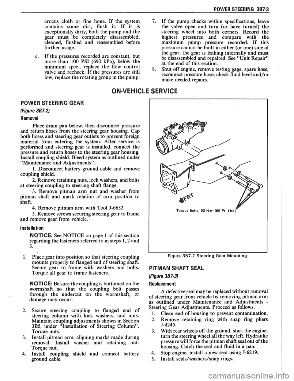
POWER STEERING GEAR
(Figure 387-2)
Removal
Place drain pan below, then disconnect pressure
and return hoses from the steering gear housing. Cap
both hoses and steering gear outlets to prevent foreign
material from entering the system. After service is
performed and steering gear is installed, connect the
pressure and return hoses to the steering gear housing.
Install coupling shield. Bleed system as outlined under
"Maintenance and Adjustments".
1. Disconnect battery ground cable and remove
coupling shield.
2. Remove retaining nuts, lock washers, and bolts
at steering coupling to steering shaft flange.
3. Remove pitman arm nut and washer from
pitman shaft and mark relation of arm position to
shaft.
4. Remove pitman arm with Tool J-6632.
5.
Remove screws securing steering gear to frame
and remove gear from vehicle.
Installation
NOTICE: See NOTICE on page 1 of this section
regarding the fasteners referred to in steps 1,2 and
3.
1. Place gear into position so that steering coupling
mounts properly to flanged end of steering shaft.
Secure gear to frame with washers and bolts.
Torque all gear to frame fasteners.
NOTICE: Be sure the coupling is bottomed on the
wormshaft so that the coupling bolt passes
through the undercut on the wormshaft, or
damage may occur.
2. Secure steering coupling to flanged end of
steering column with lock washers, and nuts.
Maintain coupling adjustments shown in Section
3B5, under "Installation of Steering Column".
Torque nuts.
3. Install pitman arm, aligning marks made during
removal. Install washer and retaining nut.
Torque nut.
4. Install coupling shield and connect battery
ground cable.
Torque Bolts: 90 Nm (66 Ft. ~bs.r
Figure 3B7-2 Steering Gear Mounting
PITMAN SHAFT SEAL
(Figure 387-3)
Replacement
A defective seal may be replaced without removal
of steering gear from vehicle by removing
pitman arm
as outlined under Maintenance and Adjustments
-
Steering Gear Adjustments. Proceed as follows:
1. Clean end of housing to prevent contamination.
2. Remove retaining
ring with snap ring pliers
J-4245.
3. With rear wheels off the ground, start the engine,
turn the steering wheel all the way left. Hydraulic
pressure will force the
pitman shaft seal out of the
housing. Catch the seal and fluid in a pan.
4. Stop engine, install a new seal using 5-6219.
5. Install seals/washers/snap rings.
Page 208 of 1825

POWER STEERING 387-1 6
7 1 1 9. DISASSEMBLE AND ASSEMBLE RACK
1 PISTON
I DISASSEMBLE ASSEMBLE
1 Disassemble parts 1 Assemble parts
as shown as shown
2 Clean and Inspect all parts for excessive wear The black balls are smaller than
the silver balls. The black and
silver balls must
be installed
alternately into the rack-piston
and return guide to maintain
rack piston to worm gear
praloed.
TEFLON SEAL AN0 0 RING--
If replaced lubricate new seal
and 0 rlng wlth power steerlng fluid
Turn worm until worm groove IS al~gned w~th the lower
I \ WORM-Slide all the way
I \
Into the ra~k-~lston
1
v Lubr~cate balls wlth
I / oower steerlno fluid install balls th;ough Before assembling rack
ball return gulde hole In houslng. ball retalner whlle rotatlng worm J-21552 must be lnserted counterclockw~se Into rack to allow
removal of worm
- GUIDE-Alternately ~nstall rema~nder of
balls and retaln w~th grease at each
end of gu~de
to 5 Newton Metres (4 Ft Lbs )
10. REMOVE AND INSTALL PITMAN SHAR
SEALS AND BEARING
REMOVE INSTALL
1 Clean end of 1 Coat seal Ilp and washer face houslng thoroughly with anhydrous calclum grease
to prevent dlrt from enterlng and be 2. Install parts as shown
extremelv careful not
to score
(he houslng
bore HOUSING ASSEMBLY
Inspect for burrs
2 Remove retalnlng rlng wlth snap rlng pllers J-4245
3 Uslng screw drlver. pry seals and washers
from bore
PITMAN SHAFT SEAL
(SINGLE LIP)
PITMAN SHAFT SEAL
(DOUBLE LIP)
RETAINING
RING 2
SEAL BACK UP WASHER NEEDLE BEARING
Remove onlv 11 ~t I - - - - - .- - - - . - . - . -. . - - 1 needs replacing.
I
When tool bottoms on
fully Installed
I I
L ------------ J L ----------- J
Install Pltman shaft bearlng Install Pttman shaft seals
CI I J
Figure 387-16 Overhaul 800f808 Gear, Chart E
Page 257 of 1825
481-4 REAR AXLE
Gear Noise
Gear noise (whine) is audible from 20 to 55 mph
under four driving conditions:
1. Light Acceleration - Accelerate slowly.
2. Road Load
- Car
driving load or constant speed.
3. Float - Using enough throttle to keep the car from
driving the engine
- car slows down gradually but
engine still pulls slightly.
4. Coast - Throttle closed and car in gear.
Bearing Noise
Bad bearings generally produce more of a rough
growl or grating sound, rather than the whine typical
of gear noise. Bearing noise frequently "wow-wows" at
bearing rpm, indicating a defective pinion or rear axle
case side bearing. This noise could easily be confused
with rear wheel bearing noise. Inspect and replace as
required.
Rear Wheel Bearing Noise
A rough rear wheel bearing produces a noise
which continues with car coasting at low speed and
transmission in neutral. Noise may diminish some by
gentle braking. With rear wheels jacked up, spin rear
wheels by hand while listening at hubs for evidence of
rough (noisy) wheel bearing.
Knock At Low Speeds
Low speed knock can be caused by worn
universal joints or a side gear hub counterbore in a case
that has worn oversize. Inspect and replace universal
joint or case and side gear as required.
Backlash Clunk
Excessive clunk with acceleration and deceleration
is caused by worn differential pinion gear shaft, excessive
clearance between axle shaft and side gear splines, exces-
sive clearance between side gear hub and counterbore in
case, worn pinion and side gear teeth, worn thrust washers
and excessive drive pinion and ring gear backlash. Re-
move worn parts and replace as required, selecting close
fitting parts when possible. Adjust pinion and ring gear
backlash.
DIAGNOSIS
1. Noise
is the same in "Light Acceleration" or
"Coast".
a. Road noise.
b. Tire noise.
c. Front wheel bearing noise.
d. Rear axle bearing noise.
2. Noise changes on a different type of road.
a. Road noise.
b. Tire noise.
3. Noise tone lowers as car speed is lowered.
a. Tire noise.
b. Front
wheel bearings and rear axle bearings.
c. Gear noise.
4. Similar noise is produced with car standing and
driving. a.
Engine noise.
b. Transmission noise.
c. Exhaust noise.
5. Vibration.
a. Rough rear axle bearing.
b. Unbalanced or damaged propeller shaft.
c. Tire unbalance.
d. Worn universal joint in propeller shaft.
e. Mis-indexed propeller shaft at pinion
flange.
f. Pinion flange runout too great.
6. A knock or click approximately every two
revolutions of the rear wheel.
a. A rear axle bearing.
b. Worn case.
7. Noise most pronounced on turns.
a. Rear axle side gear and pinion noise,
differential gear noise.
b. Axle bearings.
8. A continuous low pitch whirring or scraping
noise starting at relatively low speed.
a. All bearing noise.
9. Drive noise, coast noise or float noise.
a. Ring
and pinion gear noise.
b. Front
pinion bearing noise, coast or drive.
c. Axle bearing noise.
10. Clunk
on
acceleration or deceleration.
a. Worn
rear axle pinion shaft splines.
b. Side
gear hub counterbore in case worn
oversize.
c. Worn U-joints.
d. Excessive transmission backlash.
e. Worn axle shaft splines.
11. Chatter on turns.
a. Wrong
lube in rear axle.
b. Clutch
cone worn or spalled.
12. Clunk
or knock on rough road operation.
a. Worn suspension bushings.
PRE-REPAIR INVESTIGATION AND TROUBLE
DIAGNOSIS
A carefull diagnosis of the rear axle prior to
disassembly will often reveal valuable information as to
the extent and type of repairs or adjustments necessary.
Since frequent causes of axle noises are improper
backlash, pinion bearing pre-load, or side bearing
pre-load, or a combination, a few simple adjustments
may be all that are necessary to correct a problem.
Before disassembling the rear axle, the following
checks should be made with the results recorded and
analyzed: 1) Backlash;
2) Total Assembly Preload; 3)
Tooth Contact Pattern Test; 4) Fluid Level; and 5)
Fluid Contamination.
If axle shaft end play is excessive then check
bearings, retainer, and bolts securing backing plate.
The axle bearings could be worn and need replacement.
The four bolts or nuts securing the brake backing plate
may be loose, stripped, or missing. If the inner bearing
retainer worked loose it must be replaced.
Use care at all times to keep dirt and other foreign
matter, such as grinder dust, soot or sand, away from
differential to prevent possibility of subsequent failure.
Page 282 of 1825
REAR AXLE 48-9
lnstall or Connect
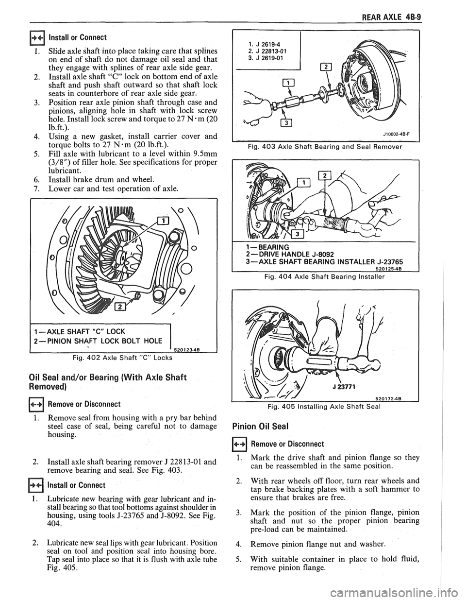
1. Slide axle shaft into place taking care that splines
on end of shaft do not damage oil seal and that
they engage with splines of rear axle side gear.
2. Install
axle shaft
"C" lock on bottom end of axle
shaft and push shaft outward so that shaft lock
seats in counterbore of rear axle side gear.
3. Position
rear axle pinion shaft through case and
pinions, aligning hole in shaft with lock screw
hole. Install lock screw and torque to 27
N-m (20
1b.ft.l
4. using a new gasket, install carrier cover and
torque
bolts to 27 N-m (20 1b.ft.). Fig. 403 Axle Shaft Bearing and Seal Remover
5. Fill
axle with lubricant to a level within 9.5mm
(3/8") of filler hole. See specifications for proper
lubricant.
6. Install brake drum and wheel.
7. Lower
car and test operation of axle.
Fig. 402 Axle Shaft "C" Locks
Oil Seal and/or Bearing (With Axle Shaft
Removed)
Remove or Disconnect
1. Remove seal
from housing with a pry bar behind
steel case of seal, being careful not to damage
housing.
1 --BEARING 2- DRIVE HANDLE J-8092
3-AXLE SHAFT BEARING INSTALLER J-23765
5201 25-48
Fig. 404 Axle Shaft Bearing Installer
Fig.
405 Installing Axle Shaft Seal
Pinion Oil Seal
Remove or Disconnect
I
2.
Install axle shaft bearing remover J 22813-01 and 1. Mark the drive shaft and pinion flange so they I
remove bearing and seal. See Fig. 403. can
be reassembled in the same position. I
Install or Connect
1. Lubricate new bearing with gear lubricant and in-
stall bearing so that tool bottoms against shoulder in
housing, using tools
5-23765 and 5-8092. See Fig.
404.
2. Lubricate new seal lips with gear lubricant. Position
seal on tool and position
seal into housing bore.
Tap seal into place so that it is flush with axle tube
Fig. 405. 2.
With rear
wheels off floor, turn rear wheels and
tap brake backing plates with a soft hammer to
ensure that brakes are free.
3. Mark
the position of the pinion flange, pinion
shaft and nut so the proper pinion bearing
pre-load can be maintained.
4. Remove pinion flange nut and washer.
5. With suitable container in place to hold fluid,
remove pinion flange.
Page 283 of 1825
48-10 REAR AXLE
6. Remove oil seal by driving it out of carrier with
a blunt chisel. Do not damage carrier. Discard
seal,
7. Examine seal surface of pinion flange for tool
marks, nicks, or damage. If damaged, replace
flange as outlined under Pinion Flange
Replacement.
8. Examine carrier bore and remove any burrs that
might cause leaks around the O.D. of the seal.
1 1. J 8614-10 PINION FLANGE REMOVER JIOOO~-~B-F I
Fig. 406 Removing Pinion Flange Nut
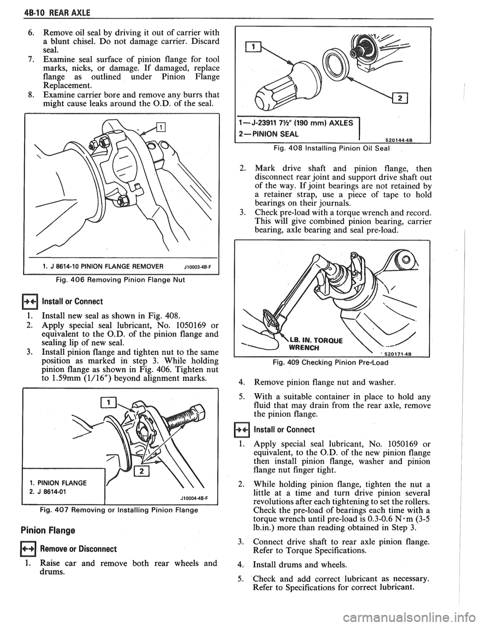
Install ar Connect
1.
Install new seal as shown in Fig. 408.
2. Apply special seal lubricant, No. 1050169 or
equivalent to the O.D. of the pinion flange and
sealing lip of new seal.
3. Install pinion flange and tighten nut to the same
position as marked in step 3. While holding
pinion flange as shown in Fig. 406. Tighten nut
to
1.59mm (1/16") beyond alignment marks.
1. PINION FLANGE Fig.
408 Installing Pinion
Oil Seal
2. Mark drive shaft and pinion flange, then
disconnect rear joint and support drive shaft out
of the way. If joint bearings are not retained by
a retainer strap, use a piece of tape to hold
bearings on their journals.
3. Check pre-load with a torque wrench and record.
This will give combined pinion bearing, carrier
bearing, axle bearing and seal pre-load.
Fig. 409 Checking Pinion Predoad
4.
Remove pinion flange nut and washer.
5. With a suitable container in place to hold any
fluid that may drain from the rear axle, remove
the pinion flange.
Install or Connect
1. Apply special seal lubricant, No. 1050169 or
equivalent, to the O.D. of the new pinion flange
then install pinion flange, washer and pinion
flange nut finger tight.
2. While holding pinion flange, tighten the nut a
little at a time and turn drive pinion several
revolutions after each tightening to set the rollers.
Fig. 407 Removing or Installing Pinion Flange Check the pre-load of bearings each time with a
torque wrench until pre-load is 0.3-0.6
N-m (3-5
Pinion Flange 1b.in.) more than reading obtained in Step 3.
Remove or Disconnect 3.
Connect drive shaft to rear axle pinion flange.
Refer to Torque Specifications.
1. Raise car and remove both rear wheels and 4. Install drums and wheels.
drums. 5. Check and add correct lubricant as necessary.
Refer to Specifications for correct lubricant.
Page 323 of 1825
586.2 DISC BRAKE CALIPER ASSEMBLY
GENERAL DESCRIPUON
This caliper has a single bore and is mounted to
the support bracket with two mounting bolts.
Hydraulic pressure, created by applying force to the
brake pedal, is converted by the caliper to a stopping
force. This force acts equally against the piston and the
bottom of the caliper bore to move the piston outward
and to move (slide) the caliper inward resulting in a
clamping action on the rotor. This clamping action
forces the linings against the rotor, creating friction to
stop the vehicle.
When the parking brake is applied, the lever turns
the actuator screw which is threaded into a nut in the
piston assembly. This causes the piston to move
outward and the caliper to slide inward mechanically,
forcing the linings against the rotor. The piston
assembly contains a self-adjusting mechanism to keep
the parking brake in proper adjustment.
NOTICE: Replace all components included in
repair kits used to service this caliper. Lubricate
rubber parts with clean brake fluid to ease
assembly. Do not
uhe lubricated shop air on brake
parts as damage to rubber components may result.
If any hydraulic
coniponent is removed or
disconnected,
it may he necessary to bleed all or
part of the brake system. Replace shoe and linings
in axle sets only. The torque values specified are
for dry,
unlubricated fasteners. Perform service
operations
011 a clean bench free from all mineral
oil materials.
ON-CAR SERVICE
CALIPER ASSEMBLY
Figures 2 thru 4
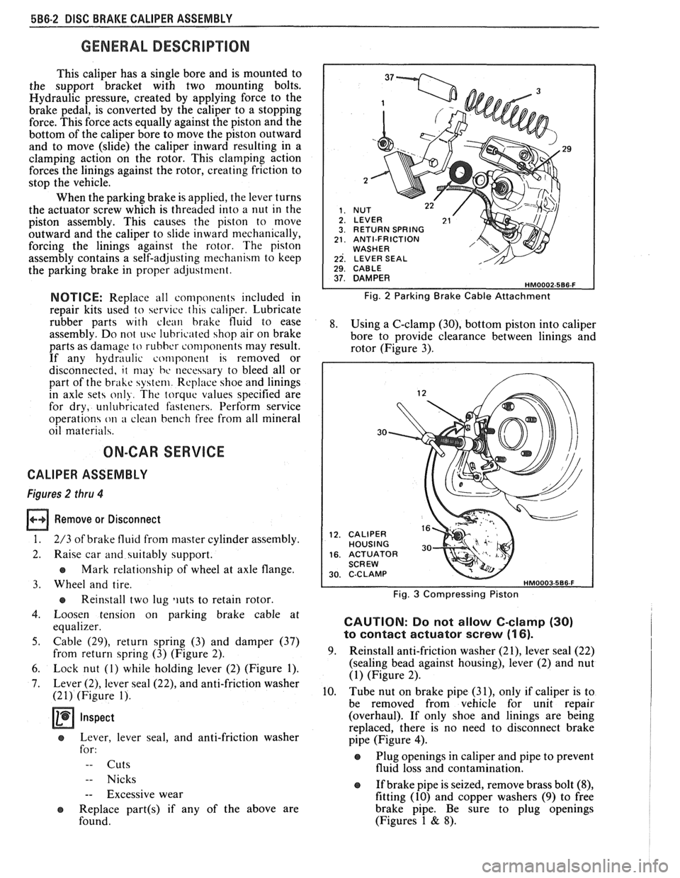
Remove or Disconnect
1. 2/3 of brake fluid from master cylinder assembly.
2. Raise car and suitably support.
e Mark relationship of wheel at axle flange.
3. Wheel and tire.
e Reinstall two lug liuts to retain rotor.
4. Loosen tension on parking brake cable at
equalizer.
5. Cable (29), return spring (3) and damper (37)
from return spring (3) (Figure 2).
6. Lock nut (1) while holding lever (2) (Figure 1).
7. Lever (2), lever seal (22), and anti-friction washer
(21) (Figure 1).
Inspect
e Lever, lever seal, and anti-friction washer
for:
-- Cuts
-- Nicks
-- Excessive wear
e Replace part(s) if any of the above are
found.
29
RETURN SPRING ANTI-FRICTION WASHER LEVER SEAL 1 29. CABLE I
Fig. 2 Parking Brake Cable Attachment
8. Using a C-clamp (30), bottom piston into caliper
bore to provide clearance between linings and
rotor (Figure 3).
30
CALIPER HOUSING ACTUATOR SCREW C-C LAMP
Fig. 3 Compressing Piston
CAUTION: Do not allow C-clamp (30)
to contact actuator screw (1 6).
9. Reinstall anti-friction washer (21), lever seal (22)
(sealing bead against housing), lever (2) and nut
(1) (Figure 2).
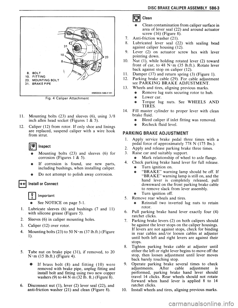
10. Tube nut on brake pipe
(31), only if caliper is to
be removed from vehicle for unit repair
(overhaul). If only shoe and linings are being
replaced, there is no need to disconnect brake
pipe (Figure
4).
Plug openings in caliper and pipe to prevent
fluid loss and contamination.
If brake pipe is seized, remove brass bolt
(8),
fitting (10) and copper washers (9) to free
brake pipe. Be sure to plug openings
(Figures 1
& 8).
Page 324 of 1825
DISC BRAKE CALIPER ASSEMBLY 588-3
BO LT
FITTING
MOUNTING
31. BRAKE PIPE
Fig. 4 Caliper Attachment
11. Mounting bolts (23) and sleeves (6), using 3/8
inch
allen head socket (Figures 1 & 5).
12. Caliper (12) from rotor. If only shoe and linings
are replaced, suspend caliper with a wire hook
from strut.
Inspect
e Mounting bolts (23) and sleeves (6) for
corrosion (Figures
1 & 5).
e If corrosion is found, use new parts,
including bushings, when installing caliper.
e Do not attempt to polish away corrosion.
Install or Connect
Important
See NOTICE on page 5- 1.
1. Lubricate sleeves (6) and bushings (7 and 11)
with silicone grease (Figure 5).
2. Sleeves
(6) in caliper mounting holes.
3. Caliper (12) over rotor.
4. Mounting bolts (23) to 50 N-m (37 1b.ft.) (Figure
1).
5.
Tube nut on brake pipe (31), if removed, to 20
N-m (15 1b.ft.) (Figure 4).
@ If brass bolt (8) and fitting (10) were
removed with brake pipe, unplug fitting and
install bolt and fitting using two new copper
washers
(9) to 44 N.m (32 lb. ft.) (Figure 8).
6. Disconnect nut (I), lever (2) lever seal (22), and
anti-friction washer (21) and clean (Figure 8).
Clean
Clean contamination from caliper surface in
area of lever seal (22) and around actuator
screw (16) (Figure 8).
7. Anti-friction washer (21).
8. Lubricated lever seal (22) with sealing bead
against caliper housing (12).
9. Lever (2) on actuator screw hex with lever
pointing down.
10. Nut
(I), while holding rotated lever (2) toward
front of car, to 48
N-m (35 1b.ft.). Rotate lever
back against stop on caliper (12).
11. Damper (37) and return spring (3) (Figure 1).
12. Parking brake cable (29). For cable adjustment
see PARKING BRAKE ADJUSTMENT.
13. Wheels and tires, aligning previous marks.
s Remove lug nuts securing rotor to hub.
e Lower car.
e Torque lug nuts. See WHEELS AND
TIRES.
14. Fill master cylinder to proper lever with clean
brake fluid.
e Bleed caliper if inlet fitting was removed.
Recheck fluid level.
PARKING BRAKE ADJUSTMENT
Apply service brake pedal three times with a
pedal force of approximately 778 N (175 lbs.).
Apply and release parking brake three times.
Raise car and suitably support.
e Mark relationship of wheel to axle flange.
Check parking brake hand lever for full release.
e Turn ignition on.
e "BRAKE" warning lamp should be off. If
"BRAKE" warning lamp is still on, and the
hand lever is completely released, pull
downward on the front parking brake cable
to remove slack from lever assembly.
Turn ignition off.
Remove rear wheels and tires.
e Reinstall two inverted lug nuts to retain
rotor.
Pull parking brake hand lever exactly four (4)
ratchet clicks.
Parking brake levers (2) on both calipers should
be against the lever stops on the caliper housings.
If levers are not against stops, check for binding
in rear cables and/or loosen cables at adjuster
until both left and right levers are against their
stops.
Tighten parking brake cable at adjuster until
either the left or right lever begins to move off the
stop, then loosen adjustment until lever moves
back barely touching stop.
Operate parking brake several times to check
adjustments. After cable adjustment is
performed, parking brake hand lever should
travel 14 clicks. Rear wheels should not rotate
forward when hand lever is applied
8 to 14
ratchet clicks.
Install wheels and tires, aligning previous marks.